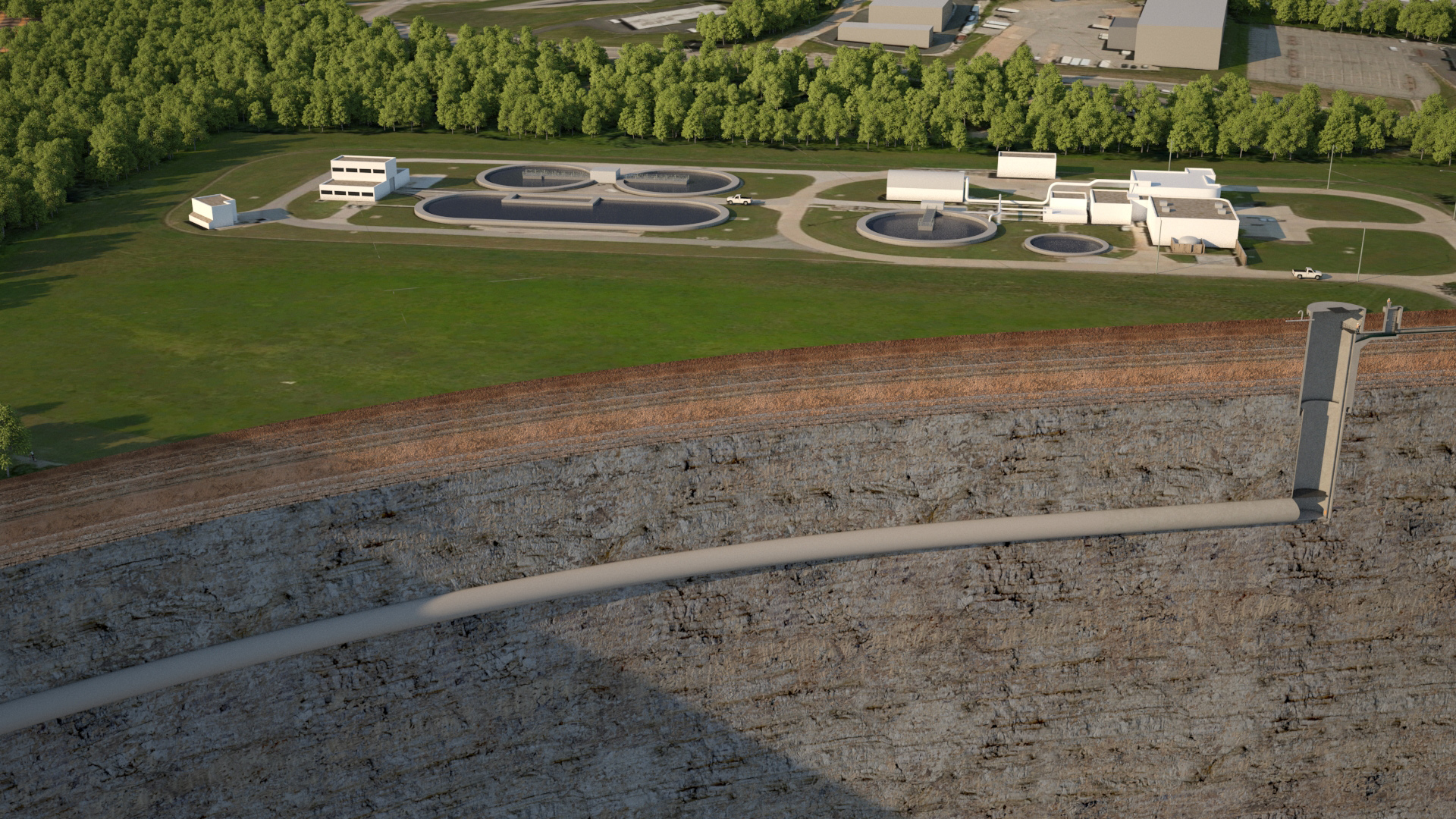
Construction recently began on the $174 million second phase of the Lower Meramec Tunnel, which will become the longest tunnel in Missouri when it enters into operation in early 2025. The 6.8 mi long sanitary sewer tunnel is a key feature of a long-standing plan to streamline wastewater collection and treatment systems in the St. Louis region, and it will contribute to ongoing efforts to improve water quality in local streams and rivers, particularly the Meramec River.
A long-range plan
The need for the tunnel was first identified in 1978, with the completion of a long-range plan for meeting state water quality standards throughout the city of St. Louis and the Missouri counties of St. Louis, St. Charles, Franklin, and Jefferson. The plan, which was developed by the East-West Gateway Council of Governments — a regional planning agency for the St. Louis metropolitan area — proposed to consolidate multiple existing wastewater treatment systems under the aegis of the Metropolitan St. Louis Sewer District.
In accordance with the plan, the MSD completed its Lower Meramec Wastewater Treatment Plant in 2007, says Jerry Jung, P.E., a senior civil engineer and project manager for the district. Treating an average of 14 mgd, the facility is intended to accept flows from smaller existing facilities, which then will be decommissioned. Also in 2007, the MSD constructed the first phase of the Lower Meramec Tunnel, which conveys flows to the Lower Meramec WWTP. As a result of that work, the MSD was able to close a wastewater treatment facility known as the Baumgartner Lagoon. The second phase of the tunnel will enable the MSD to decommission its existing Fenton WWTP, Jung says.
Connecting to phase 1
Phase 2 of the Lower Meramec Tunnel will consist of a 96 in. diameter pipeline that accepts flows from six drop structures, says Everett Litton, P.E., a senior technical principal for tunneling at the engineering consulting firm WSP and the project manager for phase 2 of the Lower Meramec Tunnel project. Beginning at the site of the existing Fenton WWTP, the tunnel essentially will parallel the Meramec River and connect to the upstream end of the phase 1 tunnel. Tunnel depths will range from 78 to 286 ft.
Although it led the design efforts for the phase 2 tunnel, WSP is a major subconsultant to HDR Inc. As a watershed consultant for the MSD, HDR is overseeing “design efforts for several tunnels, including the Lower Meramec Tunnel and associated near surface facilities,” says Doug Hickey, P.E., a vice president for HDR. “WSP was primarily responsible for design of the (phase 2) Lower Meramec Tunnel, with HDR providing project management and design of associated sewers for pump station elimination.”
Assessing groundwater inflows
Because construction of the phase 1 tunnel experienced “significant groundwater inflow,” the phase 2 design team took extra steps during the geotechnical phase, Litton says. “We did quite a bit of geotechnical investigation,” he notes. More than 70 different borings, some up to 300 ft deep, were taken along the alignment, which proceeds through two rock formations. Approximately the first mile will pass through an area known as the Warsaw formation, which consists mainly of limestone and a “significant amount of shale,” Litton says. The remainder of the tunnel extends through an area known as the Burlington-Keokuk formation, which also is limestone but with high amounts of chert.
Packer permeability testing was conducted at 10 ft intervals in borings within the rock formations to help predict the potential for groundwater inflows during tunnel construction. The process entails the use of upper and lower packers, or bladders, which are inflated to seal off an area within the borehole. Water is then injected into the area between the two packers, and the rate of inflow and the water pressure are recorded. Based on the results of nearly 500 packer permeability tests, “we are able to glean from it the permeability of the rock mass, which ultimately helps us estimate and then baseline the groundwater inflow that we expect for the tunnel,” Litton says.
Drop structure design
The 10-year design flow to the tunnel from the six drop structures will be 60.8 cfs, Litton says. More than half this flow, 35.1 cfs, will enter the tunnel from the drop structure at the site of the Fenton WWTP. By comparison, the Meramec Bottom drop structure has the next largest 10-year design flow of 12.5 cfs. The Meramec Bottom facility will enable the MSD to remove from service the Meramec Bottom Substation 7, a large pump station located in the Meramec River’s floodplain, Litton says.
Because of their higher flows, the Fenton and Meramec Bottom facilities will consist of tangential vortex drop structures designed to dissipate the energy of the flowing sewage before it falls. All six of the drop structures will include a deaeration chamber that has a vent pipe leading to the surface. “That’s so proper airflow is maintained as the sewage is dragging air into the deaeration chamber,” Litton says. “Without proper air ventilation, surging or geysering can happen within the system.”
100-year life cycle
The excavated tunnel will have a diameter of 14.5 ft before it is lined with fiberglass-reinforced polymer pipe. This material was selected because of its resistance to hydrogen sulfide corrosion and its expected long life, Litton says. “It allows the project to have a 100-year life cycle,” he notes. Meanwhile, the long-lasting material is expected to require “minimal maintenance,” Litton says.
Construction on the project began in January. Tunneling will proceed from the existing Baumgartner shaft, a construction shaft built during the construction of the phase 1 tunnel, to a shaft at the site of the Fenton WWTP. SAK Construction LLC, the general contractor for the current project, will use an open main beam tunnel boring machine. An estimated 352,000 cu yd of excavated rock will be disposed of in the area that once was the Baumgartner Lagoon, obviating the need to haul away the material by truck. “This reduces the project’s carbon footprint significantly,” Litton says.
Separately, the existing Lower Meramec WWTP is being expanded to accommodate the flows that will be provided by the phase 2 Lower Meramec Tunnel. HDR is designing the improvements, which will enable the facility to treat peak flows up to 100 mgd, Hickey says.