By Matthew J. Miller, P.E.
On June 28, 2021, bridge engineering firm Modjeski and Masters Inc. was engaged by the Union Pacific Railroad Co. to assess damages to the Dry Canyon Bridge, which had been in the path of the Lava Fire. The wildfire started on June 24 by lightning and eventually burned over 26,000 acres in the area of Weed, California.
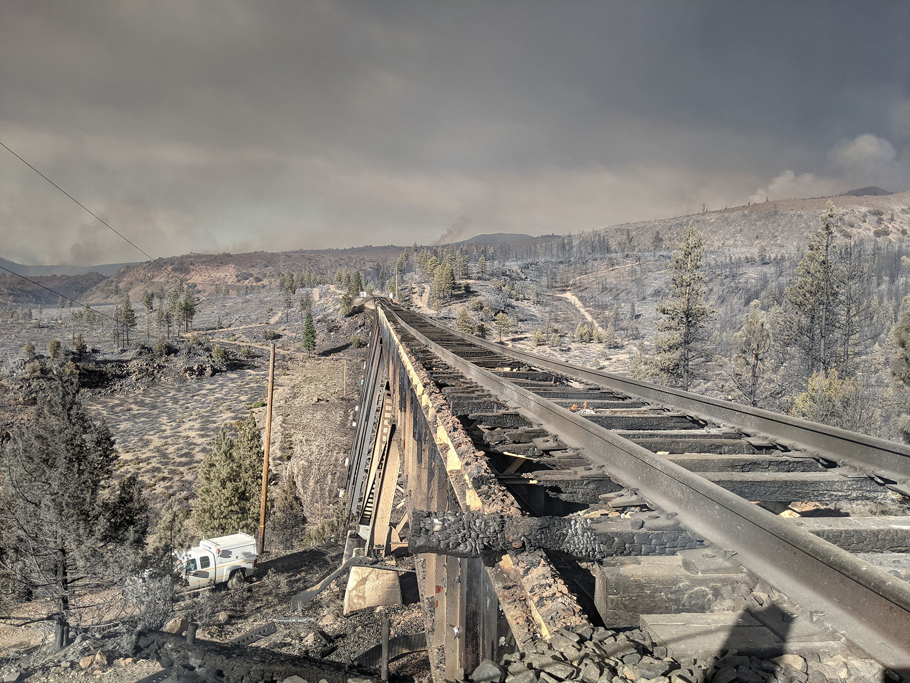
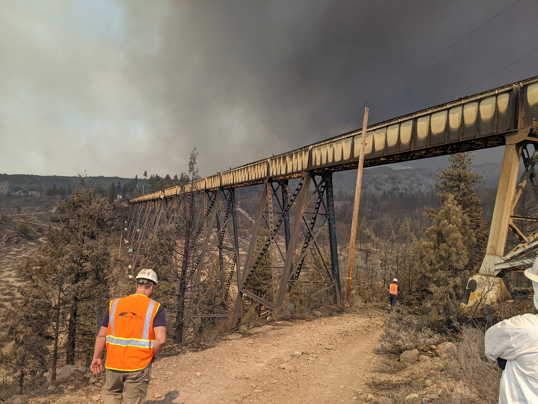
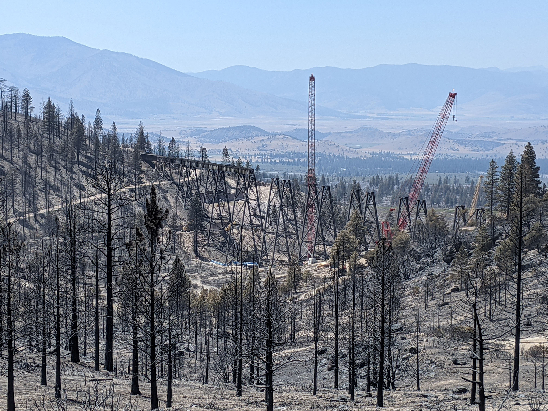
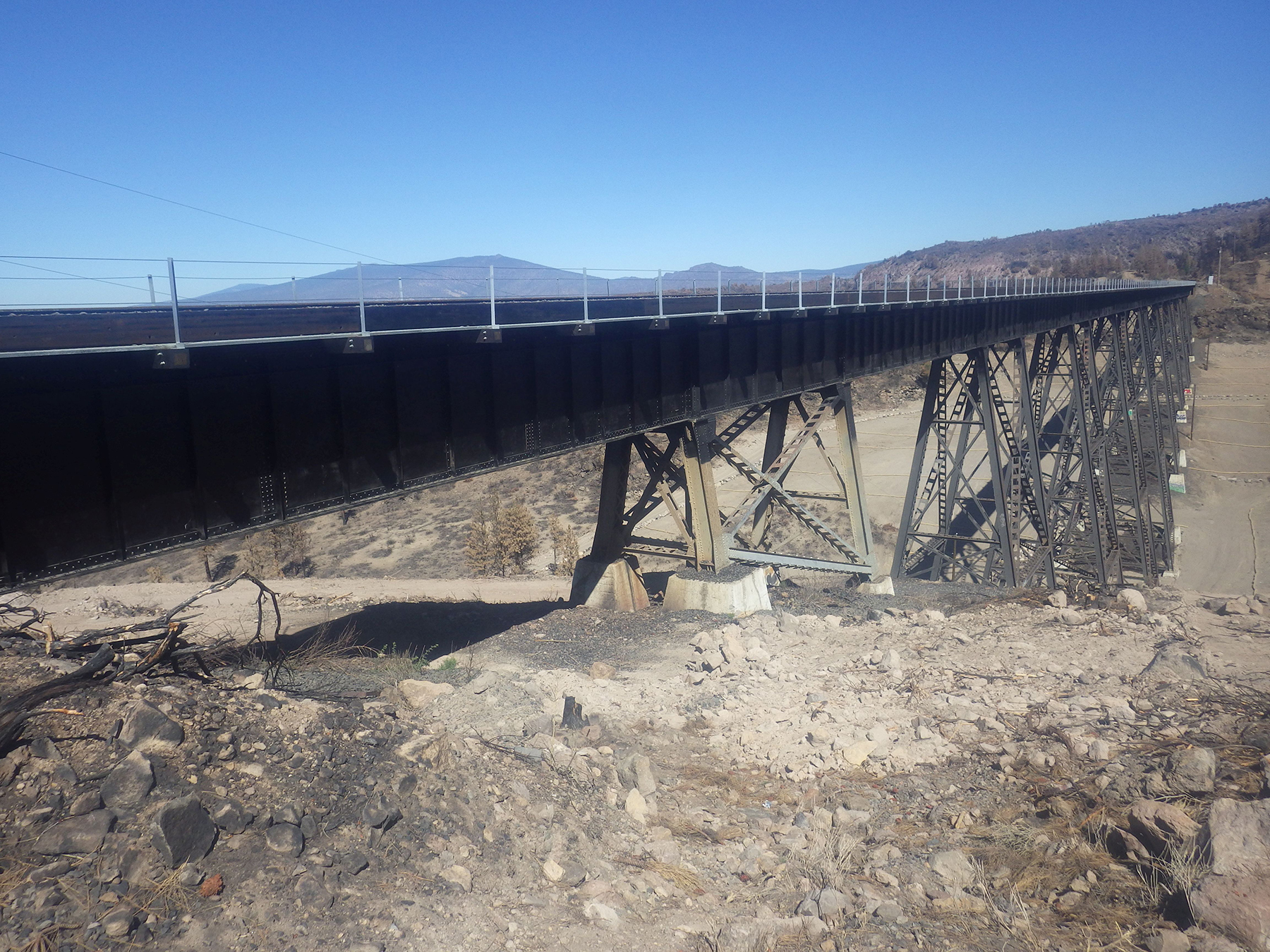
The Dry Canyon Bridge was built in 1926 as a 19-span, built-up steel deck plate girder viaduct over Dry Canyon, situated in a wooded valley off the northwest slope of Mount Shasta.
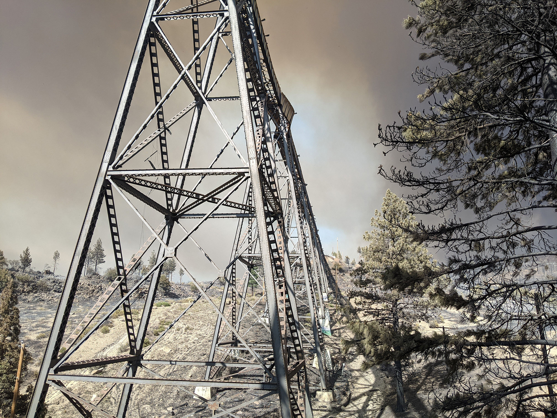
The steel girders are supported by steel bents forming towers that are founded atop concrete pedestals. Spans between supports vary in length and are 70 ft, 4 in. from abutment 1 to bent 2 and bent 19 to abutment 20; 80 ft for odd numbered spans 3 through 17; and 40 ft for even numbered spans 2 through 18. The total length of the structure is approximately 1,140 ft.
The deck comprises a ballast deck with timber ballast pan and curb. The ballast pan timbers are closely spaced with no gaps between adjacent timbers. Along with the track ties timber ballast curb, the ballast pan timbers served as fuel when the bridge burned during the Lava Fire.
Initial assessment
The Lava Fire caused varying degrees of structural damage to the deck, steel deck plate girders, towers and their concrete pedestals, and other ancillary components.
The initial assessment revealed that the timber deck burned so extensively it was unsalvageable.
It was possible to repair the steel deck plate girders, and the team developed recommended repair options after it performed an initial inspection. For this, the level of outward physical damage was evaluated first, followed by the fitness and structural integrity of the fire-exposed steel.
In the matter of the outward physical damage, the left and right girder of each span and cross-frame and lateral members were visually observed from the ground, and the estimated level of damage was documented.
The overall deformation condition of each girder was cataloged with a rating based on distortion measurements and estimates. These conditions were assessed as category 1 (appears to be generally straight or unaffected), category 2 (noticeably deformed and distorted), and category 3 (severely deformed).
Under a category 2 assessment, the deformations and distortions were still within allowable limits for repair via heat straightening. Under a category 3 assessment, the damage was determined to be outside the limits for heat straightening or uneconomical to repair.
Similarly, secondary members, including girder laterals, and cross-frames were assigned a deformation condition rating, and the percentage of members affected estimated.
Concerning the integrity of the fire-exposed structural steel, the following data were considered for gauging its fitness and structural integrity:
• Steel type and grade.
• Physical appearance and presence of heavy dark gray scale.
• Estimate of sustained temperature.
• Condition of fastener.
Most girders fell into a category 1 or 2 condition rating for deformation. Just four girders were designated category 3: the span 10 girder pair, girder 2 of span 16, and girder 2 of span 18.
A large percentage of girder top and bottom laterals and cross-frame members fell into the category 3 deformation designation.
From inspection, the 40 ft girders appeared to exhibit deformations more severe than the 80 ft girders. This was likely because the 40 ft spans were fixed to the tower at both ends, preventing them from expanding during the fire. Because they couldn't expand, they buckled. Each 80 ft span was designed with one fixed end and one expansion end, which allowed them to expand some with the fire. Damage to the long span girders was more pronounced the closer the girders were to the midspan of the bridge.
The actual magnitude and duration of heat applied to the girders is unknown, however paint residue remained on the majority of surfaces, and the steel surfaces of the girders did not exhibit the heavy scaling, pitting, and dark gray scale that would have implied oxidation consistent with severe fire damage and temperatures above the transformation temperature of steel (1,300-1,550 F).
In addition to the girder and deck damage, several towers were observed to be distorted, particularly tower 10-11 supporting span 10, which had considerable damage to the left and right longitudinal diagonal bracing closest to the top of the tower. Further, several tower anchor bolts and nuts appeared to have been freshly stretched and unseated, respectively.
During the initial three-day assessment period, UPRR engaged ZA Construction for construction support. ZA immediately mobilized equipment and a crew to begin work on constructing a road to the bridge from U.S. 97.
Repair recommendations
From the results of the initial assessment, heat straightening was recommended as the primary repair option to salvage the deck plate girder spans.
Heat straightening of the spans was ideal for this project because it provided a faster restoration of train traffic than replacement of the spans would have allowed.
UPRR engaged Dan R. Dalton Inc., a heat-straightening specialist, to perform its own evaluation of the damage for the purpose of confirming the company’s capacity for the work and an estimated time to complete it. Dalton’s assessment concluded that the 40 ft spans would take a significant amount of time to heat straighten beyond the time required to heat straighten the 80 ft and 70 ft spans.
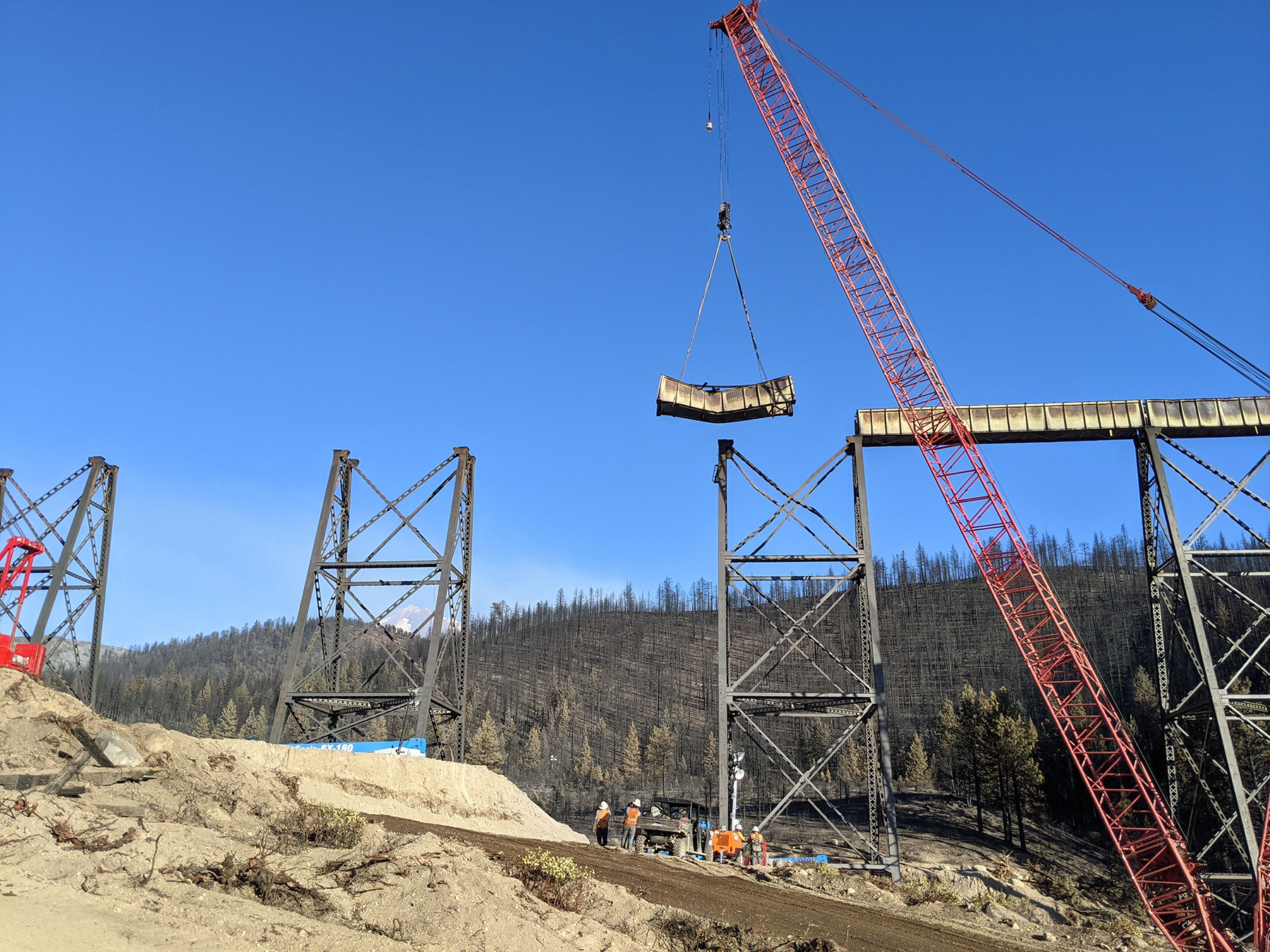
To expedite the heat-straightening schedule, Dalton recommended lowering each span to the ground in lieu of performing heat-straightening work with the girders in place. Final repair decisions considered schedule and the economics of replacement versus repair, which contributed to the decision to replace or salvage damaged bridge components.
The initial repair schedule was developed as follows:
• Remove and heat straighten the 70 ft and 80 ft spans on the ground. Replace all damaged bracing members and connection plates in kind. Replace removed and damaged rivets with new structural bolts. A total of 10 spans needed to be heat straightened.
• Remove and replace the 40 ft girders (tower spans) with similar safety stock spans owned and stored by UPRR in a Wyoming facility. Nine spans were slated for replacement.
• Evaluate and resolve unseated tower anchor bolt nuts.
• Salvage 80 ft girder sole plates and replace anchor bolts.
• Fabricate new 40 ft girder sole plates with a modified bolt pattern.
• Replace damaged tower 10-11 longitudinal diagonal bracing in kind.
• Install new timber ballast deck.
M&M identified the required materials to be replaced and provided quantities to be procured by UPRR.
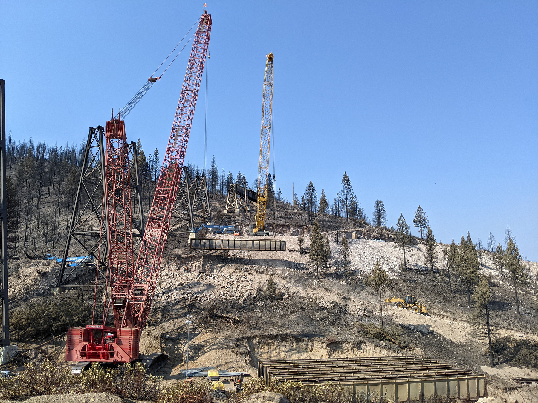
Construction
UPRR engaged three construction contractors, each with different specialties, to reconstruct the bridge on a 24/7 construction schedule: ZA, Arc Rite Welding and Fabrication LLC, and Dalton.
ZA was responsible for site preparation, removal of the existing spans, erection of the repaired and replacement spans, select structural steel fabrication and installation, and deck installation. Arc Rite was responsible for tower longitudinal diagonal bracing installation, tower cap plate installation, and select steel repairs. Dalton was responsible for heat straightening and select steel repairs.
ZA constructed four crane pads and two lay-down areas to remove and stage the spans for repairs. Construction to repair the spans began at span 19 and progressed toward span 2.
Span 19 was removed on July 2, followed by spans 17, 15, and 13 at later dates. The spans were heat straightened by Dalton on the ground at the staging areas to remediate excessive sweep, sag, and web deformation outside of acceptable tolerances in the order that they were to be reinstalled. Bent top and bottom lateral bracing, cross frame components, and associated connection plates and fasteners were replaced on the ground in coordination with the heat-straightening work. Dalton, ZA, and Arc Rite all contributed to this effort, and care was taken to ensure the spans remained square during removal and reinstallation of these bracing members.
During heat straightening of the initial first four spans (19, 17, 15, and 13), it became clear that the fire and heat-straightening process had caused an appreciable amount of permanent shortening of the spans.
Additionally, the towers retained some deformation from the spans being distorted during the fire as well as some remaining inconsequential sweep and sag in the long spans, which could not be economically or expediently resolved by heat straightening.
As a result of these dimensional changes, the position of the anchor bolt holes in the existing sole plates of the 80 ft spans would not align at most locations, and the decision was made to fabricate new sole plates for the majority of the spans to accommodate these changes.
The same conclusion was true for tower span sole plate anchor bolt holes, and their locations were modified from their design locations to match field conditions. Along with the bearing modifications, the new 40 ft girder safety stock span pairs were 6 in. wider and 1 ½ in. shorter in length than the original tower spans.
All combined, the shortening of the spans, dimensional changes at the top of the tower, and remaining distortion in the girders, as well as the safety stock girder pair’s as-built conditions, meant that the erection of each of the girders at each span location required unique considerations to fit.
The erections of spans 19 through 13 were followed by the erections of spans 2 through 12 as well as replacement of the left and right tower longitudinal diagonal members bracing bents 10 and 11. Span 10 was the final span to be erected on July 29.
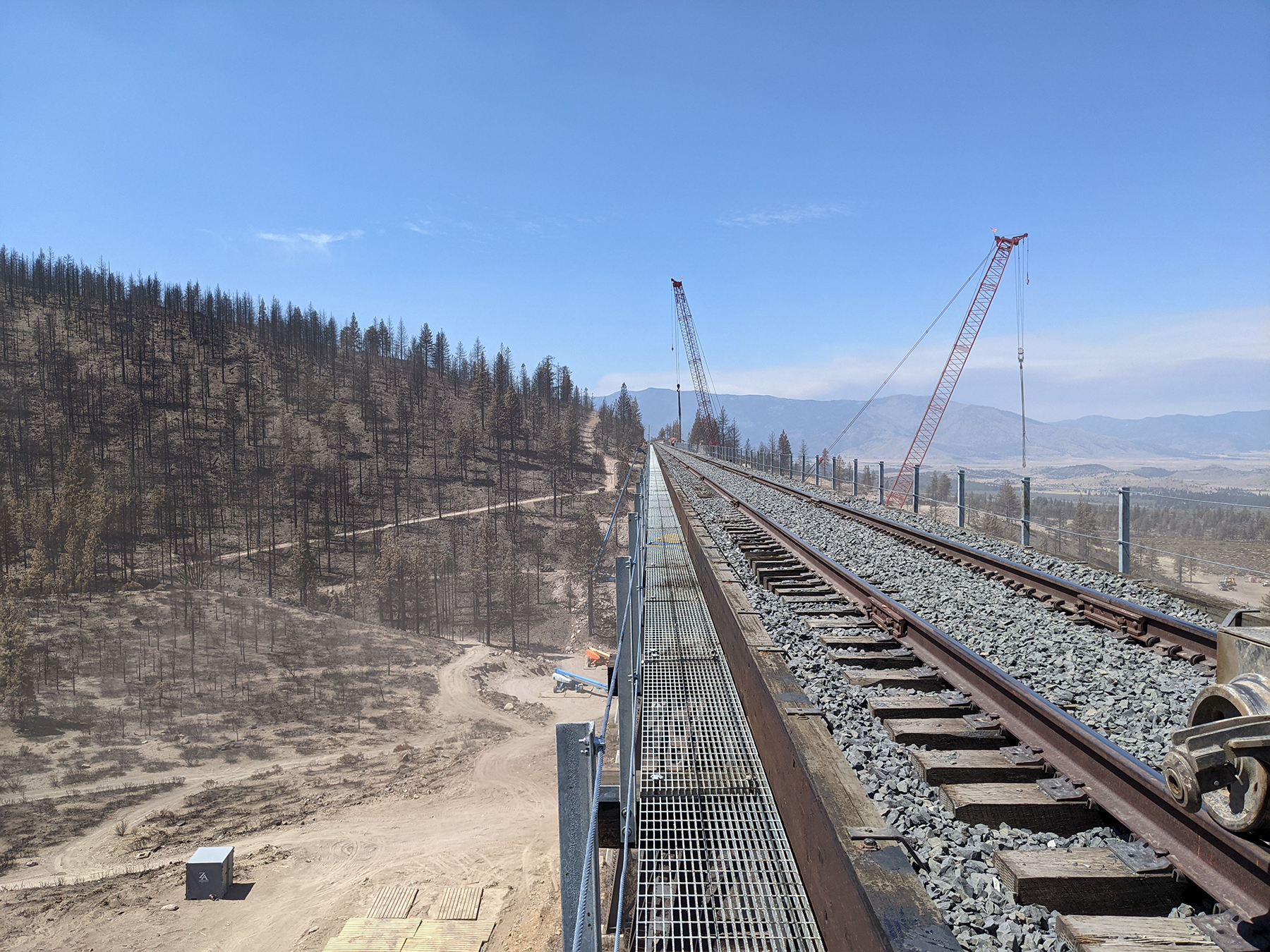
The construction and placement of the new deck followed the girder erection, working from spans 19 and 1 toward the center of the bridge. The deck was replaced in kind with added walkway and safety features. Also, the heat-straightened spans were coated with black paint on the exterior surfaces to create a uniform final appearance.
Ahead of schedule
The rehabilitation work was completed quickly and restored train traffic ahead of schedule.
The project team witnessed the first train over the bridge during a soft opening on July 31. Freight traffic resumed Aug. 1, one month earlier than expected.
Matthew J. Miller, P.E., is a project manager with Modjeski and Masters' New Orleans Field Services’ Construction Engineering and Inspection group, where he leads construction engineering and inspection efforts.