By Robert L. Reid
Like any good story from Hollywood’s hometown, the Sixth Street Viaduct in Los Angeles is about to get a sequel.
The original bridge, made mostly of concrete but with two pairs of braced steel arches, was constructed in 1932 and extended across the Los Angeles River, several railroad tracks, the U.S. 101 freeway, and various local streets. At 3,500 ft long and 46 ft wide, it was the largest of more than a dozen historical structures erected during the first four decades of the 20th century to span the Los Angeles River. But the iconic Sixth Street bridge — which appeared in numerous movies, television shows, music videos, and commercials — suffered from a fatal condition that was not understood at the time the viaduct was constructed. Its concrete included an aggregate that caused a chemical reaction known as alkali-silica reaction, which severely damaged the structure over time.
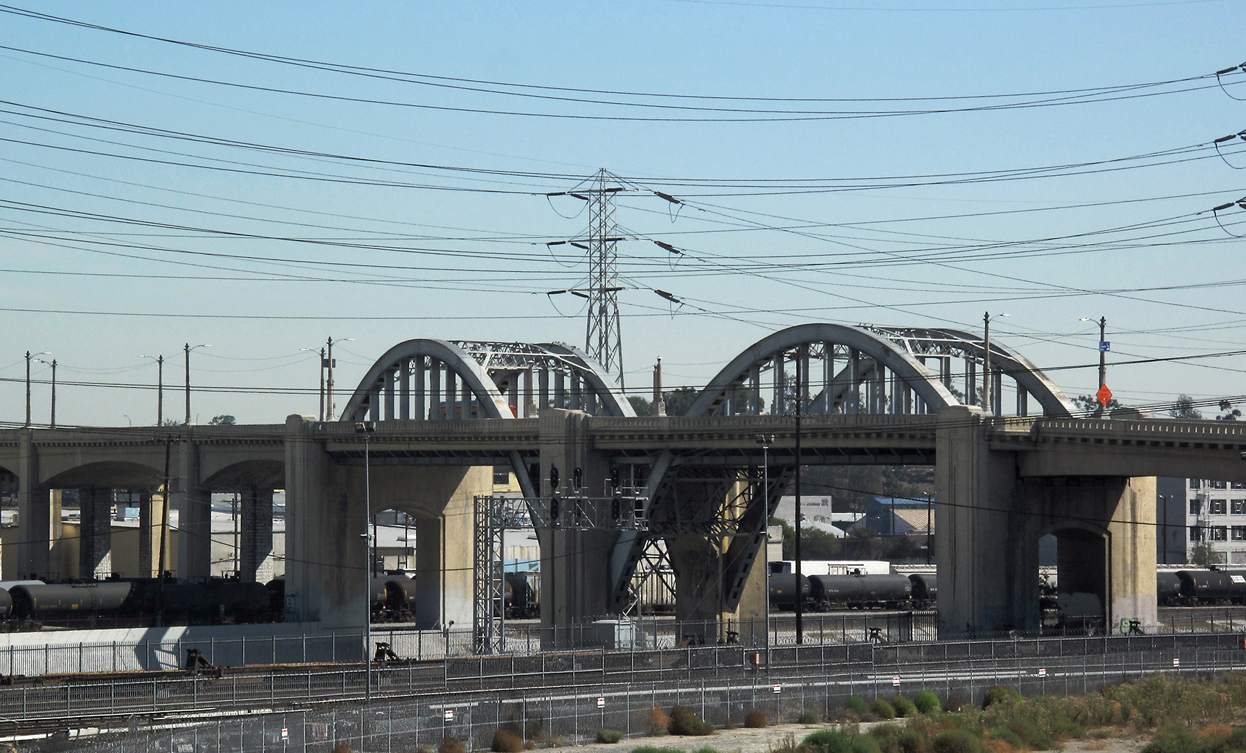
Although “various costly restorative methods were tried in an ongoing effort to save the viaduct ... all of them failed,” explains the Los Angeles Bureau of Engineering’s website about the Sixth Street Viaduct. In addition, “seismic vulnerability studies concluded that the viaduct had a high vulnerability to failure in the event of a major earthquake.”
Consequently, the original bridge was demolished in 2016. The Bureau of Engineering, together with the city’s Bureau of Contract Administration, is leading a $588 million project to replace the Sixth Street Viaduct. The new crossing, expected to be completed this summer, represents the most expensive bridge project ever in the city of Los Angeles.
Project partners
HNTB, an infrastructure design firm with offices across the nation, won a 2012 international competition to design the replacement bridge. HNTB is serving as the architect of record and engineer of record for the project.
The design team also includes Michael Maltzan Architecture, of Los Angeles.
A joint venture of New York City-based Skanska USA and Stacy and Witbeck, of Alameda, California, is the project’s construction manager and general contractor; the joint venture also demolished the original bridge under a separate contract.
COWI North America, which has key offices in North Vancouver, British Columbia, and Seattle, among other locations, is the project’s erection engineer. San Francisco-based T.Y. Lin International is the resident engineer, and Dallas-based Jacobs is the project manager.
Paying tribute
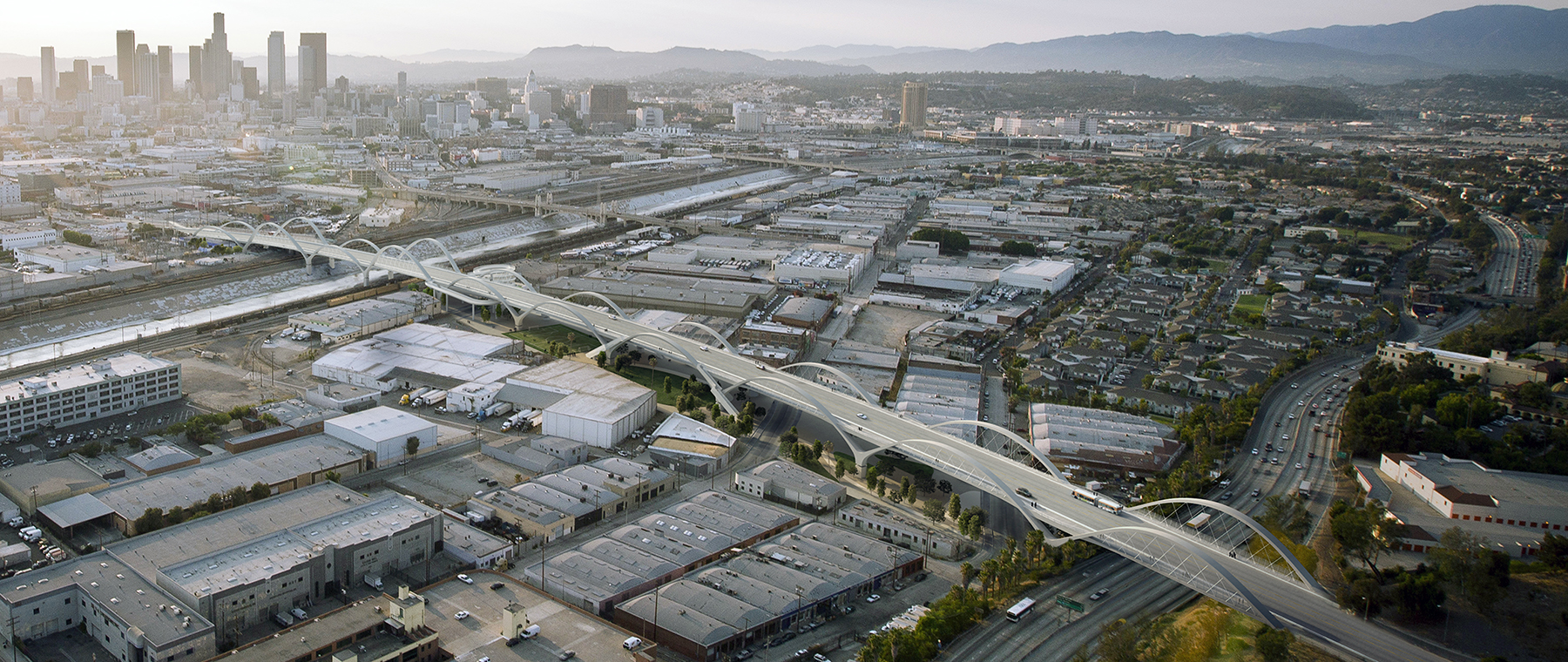
The new bridge follows approximately the same east-west alignment, connecting Los Angeles’ Arts District with the Boyle Heights neighborhood but is much wider — at 100 ft — than the original. The crossing will feature two lanes of vehicular traffic in each direction plus protected bicycle lanes and pedestrian walkways on each side.
The project is using a low-shrinkage, 6,000 psi concrete mix to accommodate the nearly 3,100 ft length of the bridge between its expansion joints, which are placed only at each abutment, says Michael Jones, P.E., S.E., M.ASCE, HNTB’s project manager for the project and based in the firm’s Santa Ana, California, office. The concrete will not include the aggregate that caused the alkali-silica reaction, but due to the volume of concrete necessary, it will be injected with liquid nitrogen during placement to help cool the mix to reduce the potential for cracking during concrete hydration and other deleterious effects as the concrete cures, notes the Bureau of Engineering.
Other nearby bridges and intersection improvements have helped reroute traffic during the construction of the bridge.
The design of the new Sixth Street Viaduct pays tribute to the arched aesthetic of the earlier crossing, with 10 pairs of concrete arches that vary in height from 30 ft to 60 ft, with taller arches rising above the railroad tracks and U.S. 101, explains Jones. The 10 ft wide arches will typically feature 300 ft spans between bents and 9-degree outward cants with no cross bracing. Steel cable hangers 2.75 in. in diameter will support the concrete bridge deck.
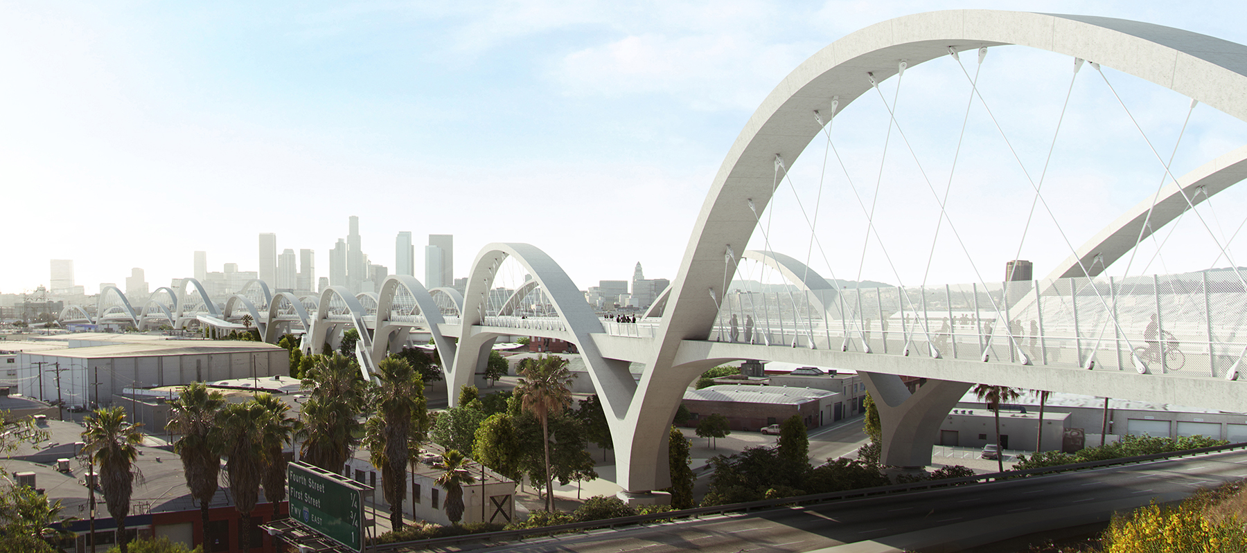
The arches form a continuous, almost undulating line from one end of the structure to the other and flow seamlessly into the substructure, which features a series of Y-shaped bents, Jones says. Continuing that seamless flow aesthetic, five sets of stairs and three bicycle ramps also connect the bridge deck to spaces beneath the crossing, where the city will construct a park, athletic facilities, and other amenities. “The goal is to make the bridge a destination point,” integrating the viaduct with the environment below, Jones adds.
Dubbed the “Ribbon of Light,” the new bridge will also feature a programmable series of LED lights that will illuminate the structure at night and help the city use the site for special events, such as Fourth of July celebrations or parades when a local sports team wins a championship, says Jones.
Seismic solutions
Seismic resilience is provided by triple-pendulum isolation bearings installed in the stem of the Y bent columns, which are supported on cast-in-drilled-hole concrete piles 10 ft in diameter that extend as much as 165 ft into the ground. The project also features a backup system with a ductile hinge detail located in the drilled hole shafts, which would only activate if bearing displacements exceed those expected in a design earthquake by a factor of two or more.
“We don’t expect the hinge will (ever) be activated,” Jones says. “But as bridge engineers we love redundancy.”
The bridge is being constructed from east to west with expansion joints only at the two abutments, says Tobias Petschke, P.Eng, Ph.D., COWI North America’s project manager. Posttensioned tendons run the length of the structure, linked by couplers, he adds.
The seismic isolation bearings, which accommodate roughly 30 in. of movement in any direction, are unstable during early construction stages, says Petschke. To ensure stability of the bearings, COWI installed lock-up devices in the columns until the installation of edge girders provided the necessary structural continuity. The lock-up devices are placed in the four corners around the seismic isolation bearings. They are secured to the columns via posttensioned anchors and consist of steel profiles welded in a cross formation and bolted together with splice plates.
Once structural continuity had been achieved through the edge girders, the lock-up devices were no longer required and were converted to shear keys to provide a longitudinal restraint to the bridge’s superstructure. This was done by removing certain splice plates and allowing rotation in the seismic isolation bearings, but at the same time maintaining the bridge in position, Petschke adds.