By Seth Knihtila, P.E., Michael Oakland, Ph.D., P.E., Aff.M.ASCE, and Matthew Farber, P.E., S.E.
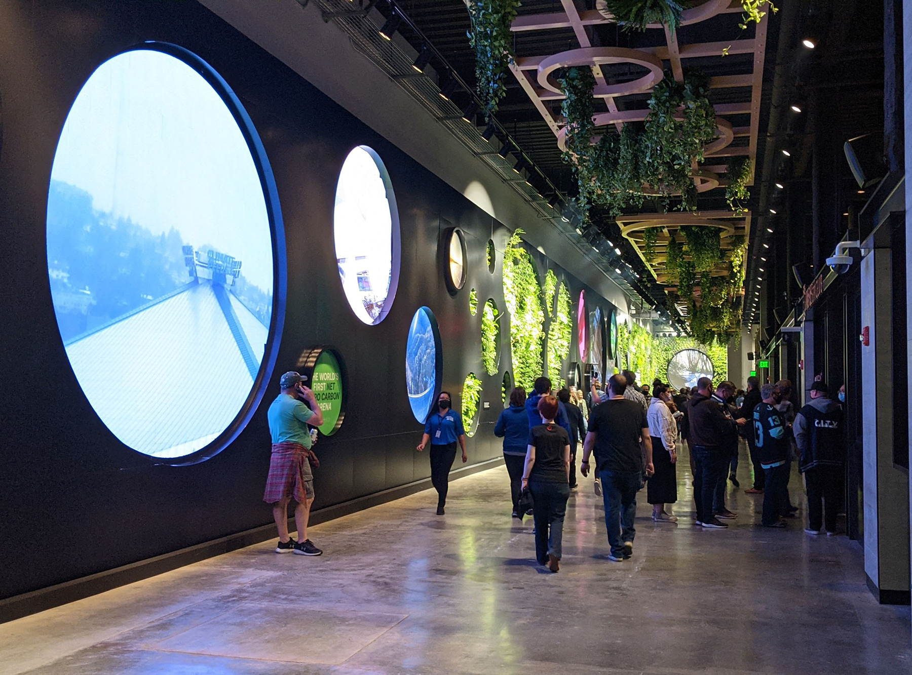
Most building projects start from the ground up. But in the case of Seattle’s Climate Pledge Arena, the work below made it possible to transform historic KeyArena into a world-class, modern venue.
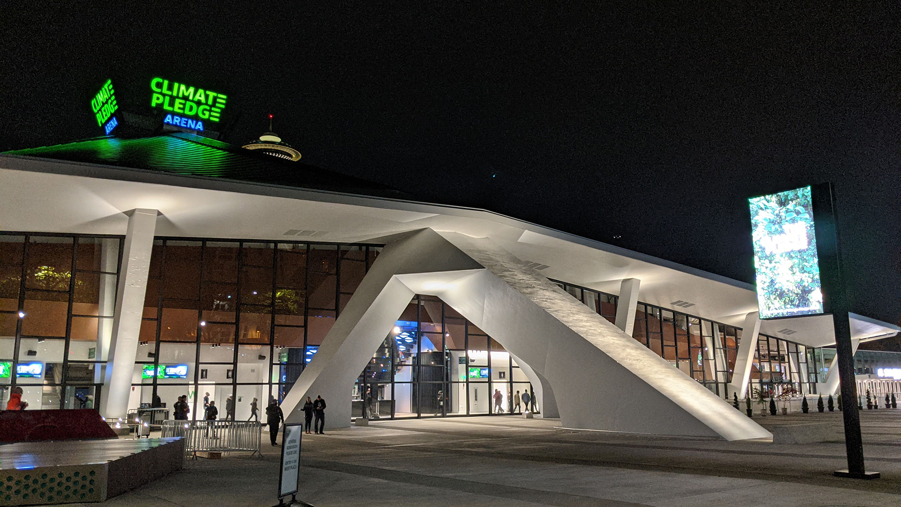
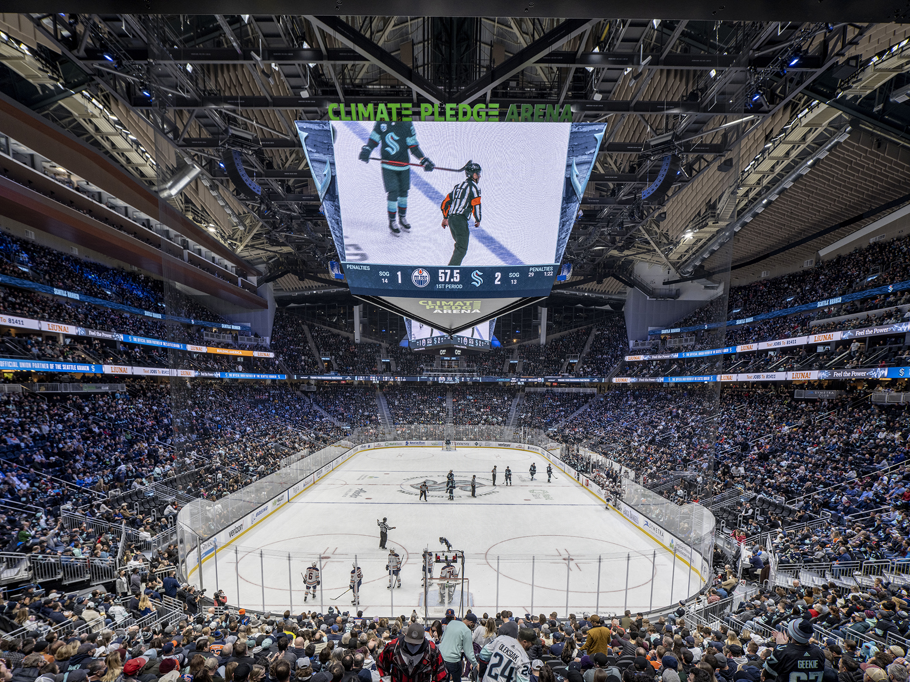
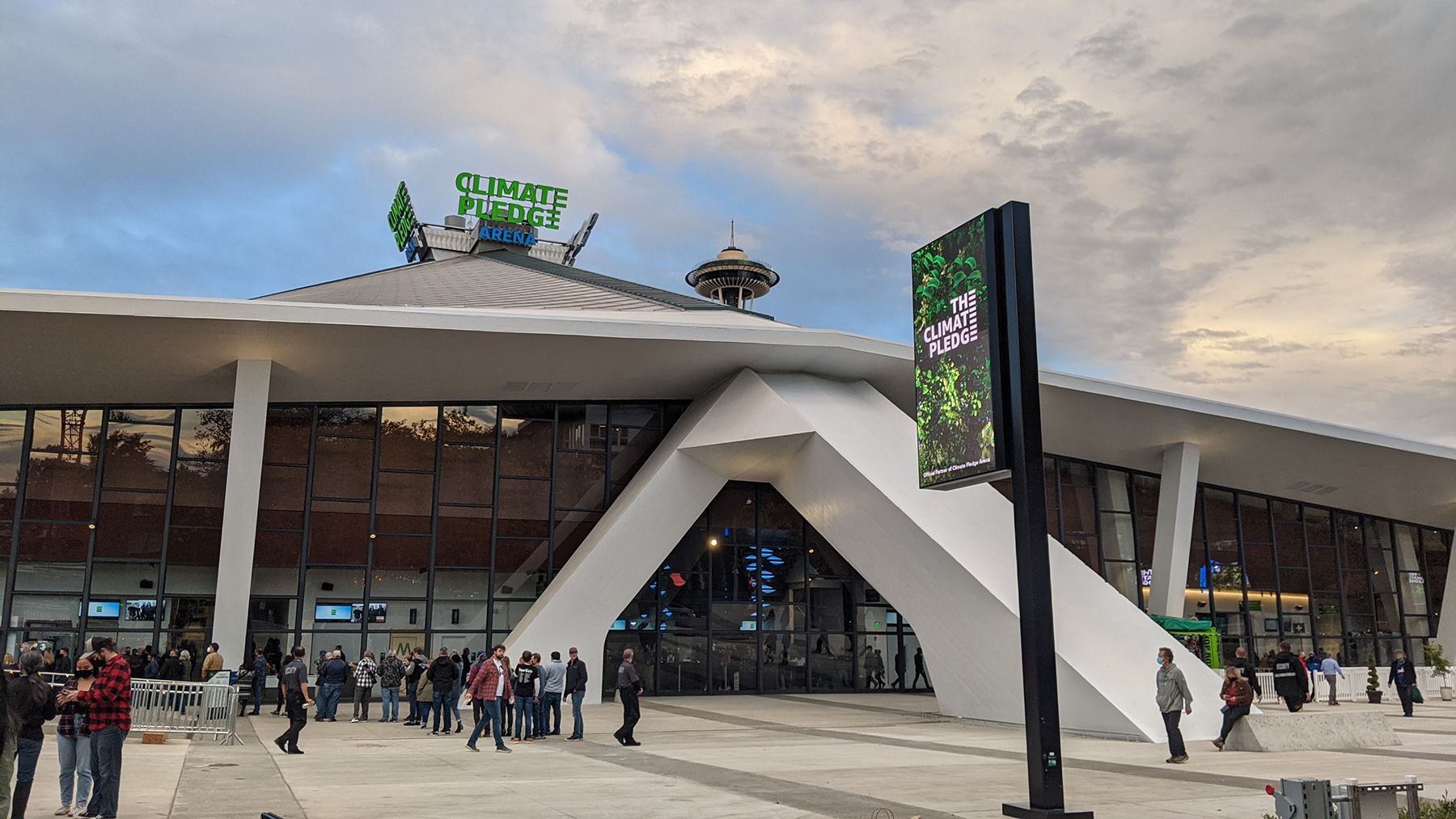
When the new home to the NHL’s Seattle Kraken and the WNBA’s Seattle Storm opened its doors in October 2021, fans likely appreciated the arena’s new look, amenities, and high-tech features, without giving much thought to the work that went into it. The expansion and renovation of the 800,0000 sq ft arena by the Oak View Group — an advisory, development, and investment company that focuses on sports and live entertainment — presented several complex challenges for the architect Populous and Thornton Tomasetti, the project’s structural, geostructural, facade, and construction engineer.
Key challenges
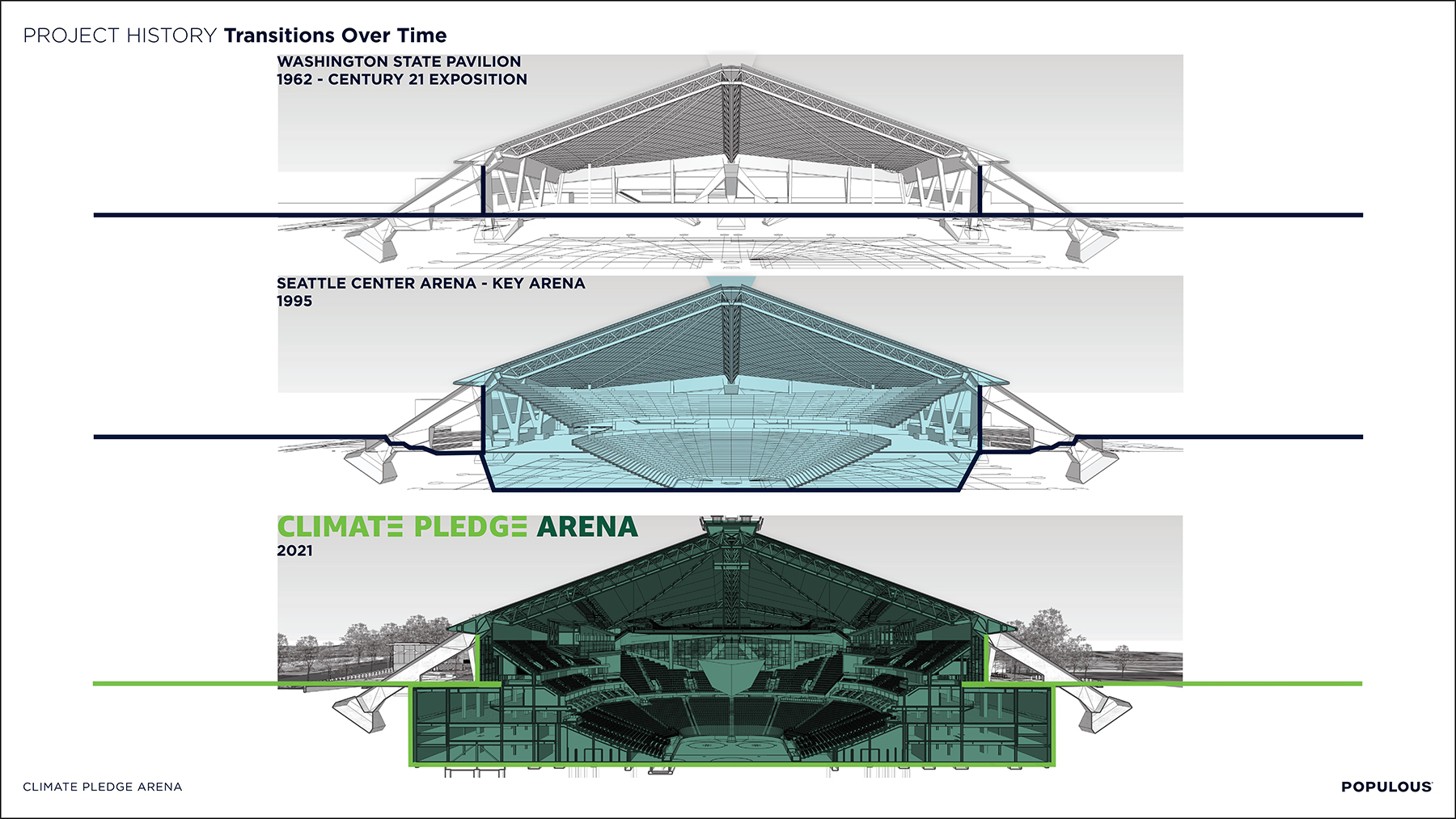
Originally designed by modernist architect Paul Thiry and constructed for the 1962 Seattle World’s Fair, KeyArena — just north of downtown — was the longtime home of the NBA’s Seattle SuperSonics until the team relocated to Oklahoma City in 2008. The venue was built at grade at the plaza and street level and could accommodate up to 13,200 people.
Plans for the new below-grade venue called for an expansion to more than 17,000 seats for hockey, basketball, concerts, and other events, along with a new parking garage.
In 2017, the Seattle Landmarks Preservation Board classified KeyArena as a local landmark. This distinction came with the strict requirement that the original roof, curtain wall, and exterior concrete elements remain intact as part of the renovations. This requirement meant that significant portions of the new, larger arena would need to be constructed below grade and outside the perimeter of the existing arena.
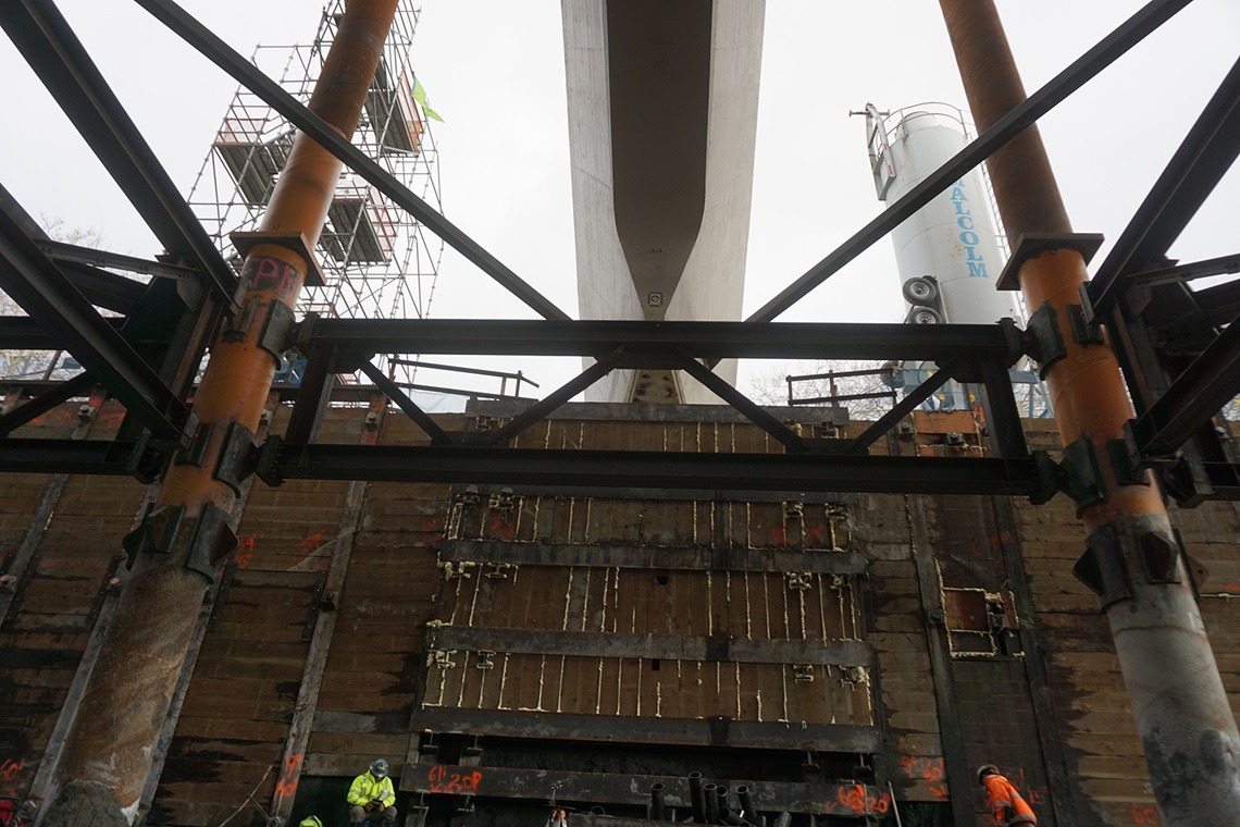
To achieve the project goals while retaining the historic fabric of the structure, the project team had to devise innovative solutions. Most notable among the challenges was determining how to demolish the existing structure’s interior and excavate 680,000 cu yd of soil in order to make room for the new below-grade venue, all while temporarily supporting the 44 million lb, 400 ft by 400 ft existing roof structure.
The new Climate Pledge Arena consists of an event level 15 ft below the previous undersized event floor elevation, four complete arena levels at and below the surrounding grade, and two levels above the surrounding grade. The design team first needed to address how to significantly expand the below-grade program space underneath and beyond the existing concrete roof.
Previous renovations, most recently in 1995, included open, sloped excavations that did not undermine the existing arena foundations and were generally self-supporting.
To create the new five-level seating bowl, a vertical foundation wall was constructed on all four sides of the new building outline to retain soil, groundwater, and surcharge loads from adjacent existing buildings and roadways.
This 65 ft deep perimeter foundation wall system presented multiple challenges. The open arena bowl and truncated seating at the north end meant there were no continuous interior floor plates to help retain the new foundation walls. After considering a range of options, the project team determined that permanent tieback anchors for the foundation wall system were the only practical means of support for the new arena and garage.
Selecting a wall system
The wall system had to be stiff enough to limit lateral deflections, especially around the existing pylons that would remain in service during and after construction to support the roof. The wall system also needed the flexibility to accommodate complex snorkels, the subterranean passages at each corner of the structure that provide egress, air intake, and air exhaust in the arena’s lower levels. Another requirement involved finding an earth-retention system that could also serve as the permanent foundation wall, obviating the need to use additional structural components for temporary support.
The project team closely evaluated the benefits and challenges of various earth-retention systems, accounting for the performance, longevity, constructability, and cost of each option. In the end, the selected system consisted of soldier piles and tiebacks with temporary wood lagging to support the earth during excavation and a shotcrete face to provide permanent support.
The soldier piles offered the stiffness required to control deflections while providing flexibility in the layout. The piles also enabled the complex foundation wall configurations within the snorkels.
Clashing tiebacks
After the selection of the perimeter wall system, several unique construction and design challenges arose. The design challenges included how to lay out the tiebacks so as not to affect the existing pylons and their foundations, which had to remain in place. The tiebacks had to be severely splayed at multiple angles to get around the pylons.
As a result, many tiebacks, in multiple rows, crossed over one another, creating numerous clashes that had to be resolved. The soldier piles were closely spaced on either side of the pylon footings with tightly spaced horizontal steel waler beams and vertical wood lagging to span portions of the wall where the tiebacks could not be used.
As for other complications, foundations supporting adjacent existing structures, numerous utilities, and protected trees existed on all four sides of the excavation. On the southern side, tiebacks also had to extend below public rights of way, which required special permitting and depth requirements regarding where tiebacks could be installed. The design team had to rely on innovative tools, such as virtual imaging, to identify and resolve conflicts in the spaghetti-like mass of tiebacks required to support the walls.
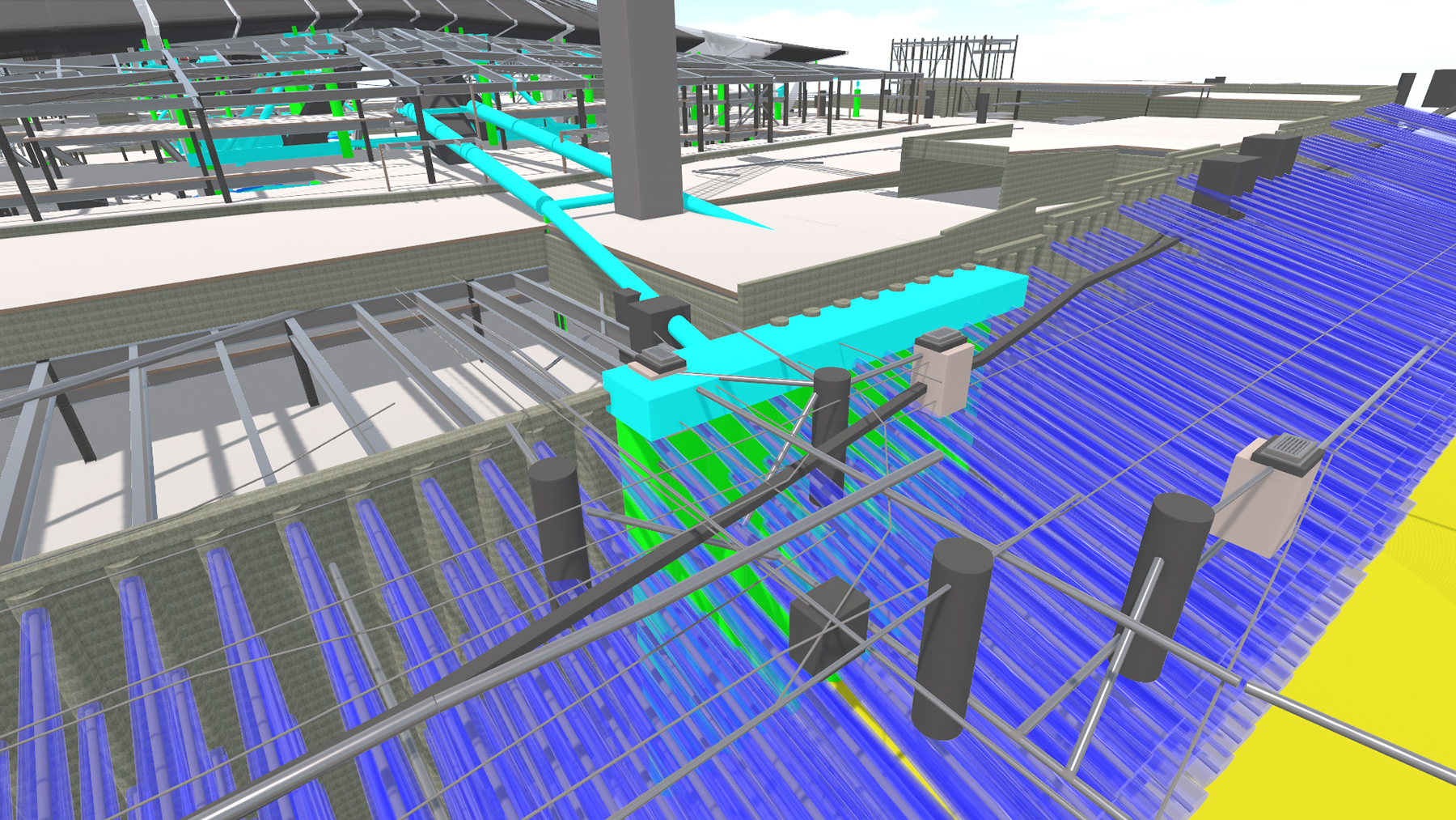
The standard soldier pile included pile sleeves through the web of the soldier pile at each tieback location to avoid rotational twisting that could cause reflective cracking in the shotcrete face. Access for drilling tiebacks directly at the soldier pile was not possible at some corner locations, nor was it possible at locations where temporary roof-support columns were added after the soldier piles had been fabricated. Meanwhile, some changes were made to tieback locations as the construction progressed to address conflicts with existing elements or construction sequencing with the temporary roof-shoring structure.
To help deal with unanticipated conflicts encountered during construction, Thornton Tomasetti developed a unique type of waler, or horizontal beam. Known as a “stub waler” because of its small size, the beam could be installed between soldier piles in the field. As conflicts were identified, the stub walers afforded flexibility in terms of where tiebacks could be located.
Because the soldier piles were fabricated well ahead of construction, crews needed some means to accommodate tiebacks that had to be relocated during construction without interfering with the permanent structure. This degree of flexibility to adapt to actual field conditions could have only been achieved using the systems of soldier piles and lagging with the stub walers.
Subterranean snorkel blues
Because most of the new arena was below grade and because of the requirement to preserve the historic curtain wall, the subterranean snorkel structure was needed to supply and return air into and out of the building. The snorkels proved to be the most complex and challenging aspects of the design and construction of the earth-retention system for the arena.
Because of the landmark status of the existing facade, egress stairs and air intakes needed to be shifted to the outer extent of the structure through four snorkels on each corner. Each snorkel was different and had a small footprint with respect to the relatively large excavation for the overall area. The complexity of the footprints for each snorkel required unique, temporary internal bracing layouts as well as coordination with the permanent structural elements.
The designers worked closely with the contractors during excavation, providing additional design services in several of the snorkels to streamline the excavation and construction process as the project evolved.
The southwest side had the most complex snorkel on the site, with multiple layout changes, a stormwater detention tank, and a temporary construction access ramp — dubbed the West Temp Ramp — that was added late in the overall construction sequence. Access to the arena bowl was originally from the south. With the expansion of the arena footprint to the southern limits of the site, a temporary ramp was added to the overall project to provide access to the bowl during construction by means of a gap in the perimeter soldier pile system. The ramp was supported by numerous levels of temporary tiebacks and a complex cross-lot bracing system, affording 15 ft of headroom for over-height truck deliveries down the ramp.
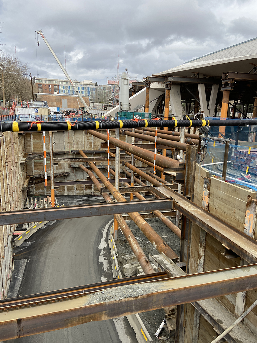
Filling the ramp
To the south, a mined tunnel underneath Lenny Wilkens Way, which was known as Thomas Street at the time, affords access to the lower level of the completed arena. During construction of the tunnel, which was designed and constructed by other parties, the West Temp Ramp provided this access instead.
Because construction of the arena advanced ahead of construction of the tunnel, the ramp had to remain open as long as possible to facilitate continued access into the lowest level of the arena.
Therefore, the ramp had to be filled in after most of the arena was constructed. This solution required intense coordination and value engineering efforts, as the initial plans to backfill the ramp with structural fill would be time-consuming and difficult because of the maze of cross-lot braces.
In the end, the designers and the general contractor/construction manager — the M.A. Mortenson Co. — developed an approach for constructing the southwestern snorkel structure that would enable it to be built ahead of the ramp closure by leaving the ramp bracing in place and allowing it to project through the walls of the snorkel structure. This bracing would be cut out and the walls filled in after the remaining portions of the ramp were filled.
To this end, a lightweight cellular concrete was used as backfill. Significantly lighter and easier to place than conventional structural fill, the cellular concrete greatly decreased the loads on the permanent foundation wall, significantly reducing the number of tie rods needed to support the backfilled area. The tie rods were attached to a reinforced-concrete deadman, which provided the passive resistance to support the load within the tie rods resulting from soil, surcharge, and earthquake loads along the perimeter wall.
The cellular concrete fill also enabled the deadman to be embedded directly within the cellular concrete, thus obviating the need to run the ties all the way to the far side of the former ramp. The innovative use of the lightweight cellular concrete as backfill material is credited with keeping the project on schedule in the critical final days of construction.
Thousands of tiebacks
Overall, the perimeter earth-retention system included more than 650 soldier piles, each of which had to be installed in a pre-drilled 30 in. diameter borehole and grouted in place. The wall is supported by 2,400 tiebacks having a total drilled and installed length of about 130,000 linear ft. Finally, the earth-retention wall facilitated the excavation of 680,000 cu yd of soil.
Although Thornton Tomasetti has designed systems that may have included larger excavations for projects, such as Boston’s Central Artery and Harvard University’s Science and Engineering Complex, this project ranks among the largest and most complex the company has designed for a tied-back soldier pile and lagging system.
In many respects, Climate Pledge Arena was a one-of-kind project. And it was all made possible with creative solutions and a whole lot of digging.
Seth Knihtila, P.E., is a project engineer, Michael Oakland, Ph.D., P.E., Aff.M.ASCE, is a vice president, and Matthew Farber, P.E., S.E., is a principal for Thornton Tomasetti.
Project credits
Owner and developer: Oak View Group
Architect: Populous
Structural, facade, geostructural, and construction engineer: Thornton Tomasetti
General contractor/construction manager: M.A. Mortenson Co.
Foundation and earth-retention subcontractor: Joint venture comprising the Malcolm Drilling Co. Inc. and Donald B. Murphy Contractors Inc
This article first appeared in Civil Engineering Online.