By David B. Peterson, P.E., F.ASCE
The Rodanthe Jug Handle Bridge in Rodanthe, North Carolina, provides a long-term, sustainable solution to an ever-present problem that plagues coastlines: erosion caused by storm surges.
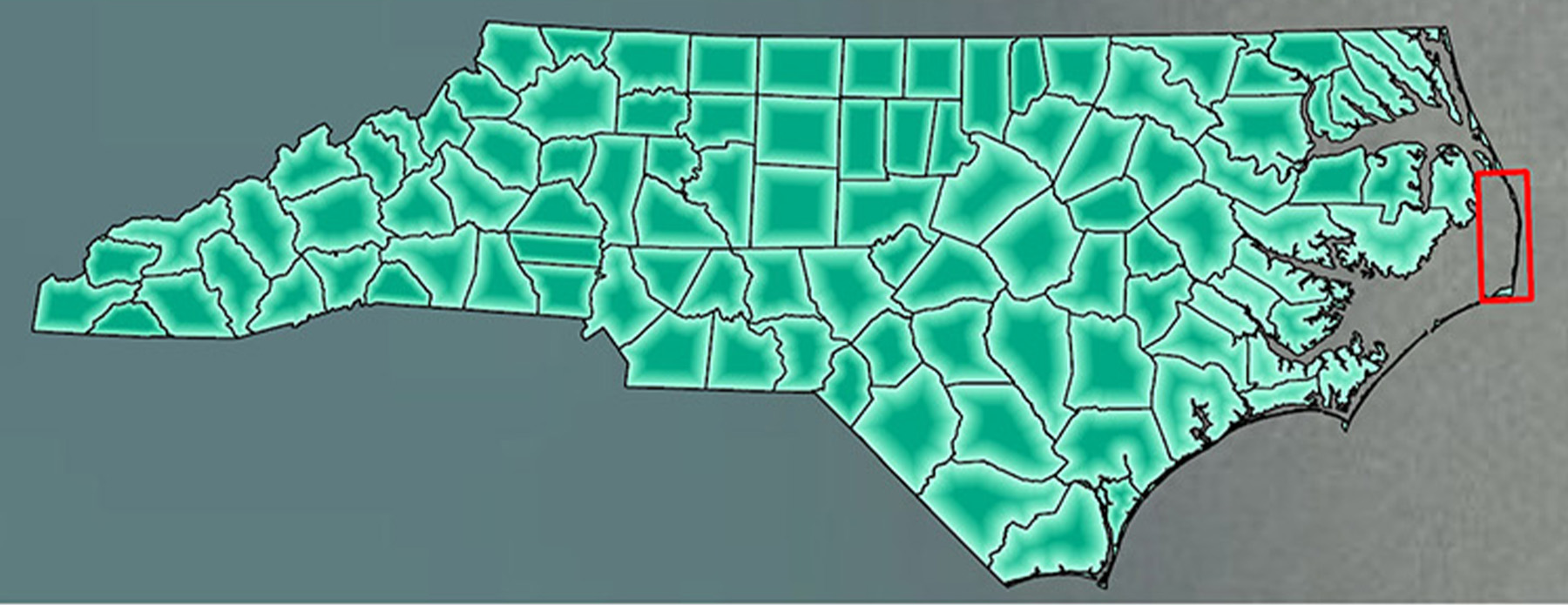
The resiliency of the built environment encounters its greatest challenges along the coastlines of the world. This conflict between the natural and built environments has been fought for decades along North Carolina’s Outer Banks, a series of barrier islands along the state’s coast.
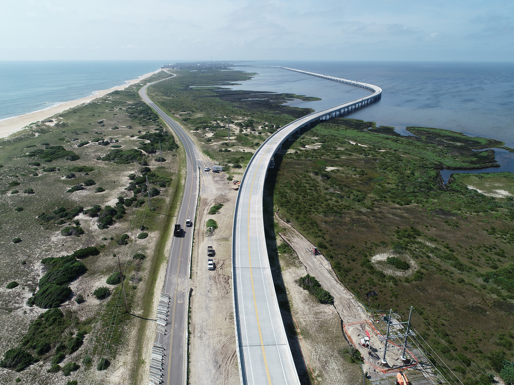
Parallel to the coast on a thin sliver of shifting sand is a stretch of North Carolina Highway 12 that runs from the Marc Basnight Bridge (formerly the Bonner Bridge) at the tip of the Oregon Inlet 72 mi south to the Ocracoke Inlet. South of the Oregon Inlet, the Atlantic Ocean can be seen over a short sand dune to the east, and the Pamlico Sound is visible to the west.
Since 2010, the North Carolina Department of Transportation has spent an average of $6 million per year to monitor and maintain six “hot spots,” or areas that were constructed to prevent high tides and repetitive storms from breaching the dunes. These breaches deposit tons of sand on the roadway and into the nearby wetlands of Pamlico Sound.
One hot spot was an S-curve just north of the town of Rodanthe. In August 2011, Hurricane Irene breached a section of NC 12 within this area, washing out the existing roadway and stranding residents. In a short-term mitigation effort to counteract hurricanes and other high-tide events, NCDOT would remove the shifted sand and place it back into the dunes that line NC 12.
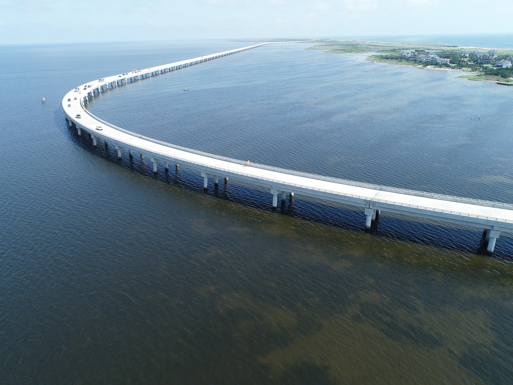
As a long-term strategy, the agency opted to build the Rodanthe Jug Handle Bridge, a 2.5 mi long viaduct that extends from the southern end of the Pea Island National Wildlife Refuge, over Pamlico Sound, and into Rodanthe.
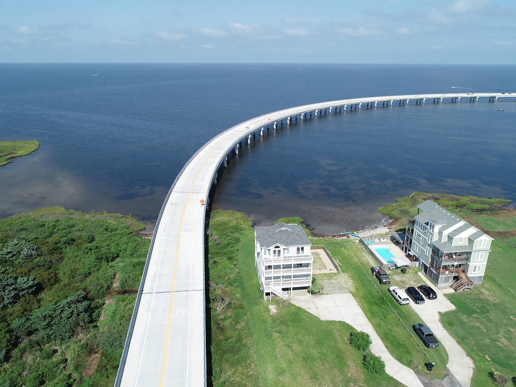
Designed to accommodate rising sea levels and render obsolete a section of roadway prone to frequent washouts, the crossing was named the Jug Handle Bridge because at its southern curve it strategically maneuvers around a historic sunken ship in the sound (a protected site), creating the structure’s signature form.
History
The lengthy planning history to mitigate the effects of storms along NC 12 began in 1993 with a draft environmental impact statement that over the years included various solutions, ranging from beach nourishment to proposals for new bridges. Ultimately, NCDOT chose to construct the Jug Handle Bridge, which features four alignments over the Pamlico Sound. These alignments are expected to maintain NC 12 inland of where the shoreline is projected to be by 2060.
NCDOT advertised the request for qualifications in November 2013. Nine design-build teams submitted statements of qualifications, and three were short-listed in August 2015. NCDOT used a best value award selection procedure that included technical quality and price. The contract was awarded to Flatiron Constructors Inc. the following January. The Flatiron design-build team included Coastal Precast Systems, DEAL S.r.l., RK&K, Wood, INTERA, Three Oaks Engineering, and RWC.
The design-build team proposed 13 alternative technical concepts during the procurement process, three of which were approved by NCDOT and included with the project. The first was a roundabout at the south end of the project at the intersection of the existing NC 12 and the mainline NC 12 (the new bridge). This five-legged, or “starfish,” roundabout is a unique traffic element for this community. Traffic will be able to maneuver between the new NC 12, the existing NC 12, and a service road without a traffic signal.
The roundabout also eliminated the need to relocate a local business, thus reducing right-of-way costs, and increased safety for the traveling public, as lower speeds are required through the intersection.
The second alternative concept mandated a future bridge extension to the north, staying over the Pamlico Sound. The connection point will be constructed somewhere within spans 70 to 76, where the edge girders were omitted to accommodate the extension. This new section will eventually connect to the Marc Basnight Bridge over the Oregon Inlet, thus increasing resiliency by removing another NC 12 hot spot (2.4 mi) that NCDOT will no longer have to maintain. (Read about the Marc Basnight Bridge in “Designed for Durability,” Civil Engineering, September 2019.)
The third NCDOT-approved alternative concept permitted the use of partial-depth precast prestressed concrete deck panels. The durability of the precast panels cast in a controlled plant environment helped meet the project’s extensive corrosion protection requirements. Additionally, the precast deck panels enabled the design-build team to accelerate the construction schedule and reduce the long-term maintenance required for the structure.
Design
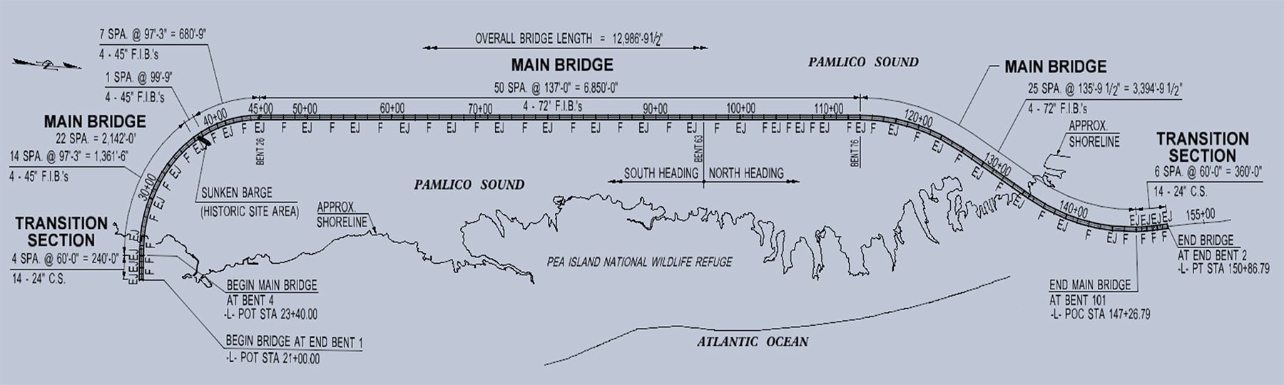
The 107-span structure was divided into five sections: the south transition (spans 1-4), the south curve main bridge (spans 5-26), the tangent main bridge (spans 27-76), the north curve main bridge (spans 77-101), and the north transition (spans 102-107).
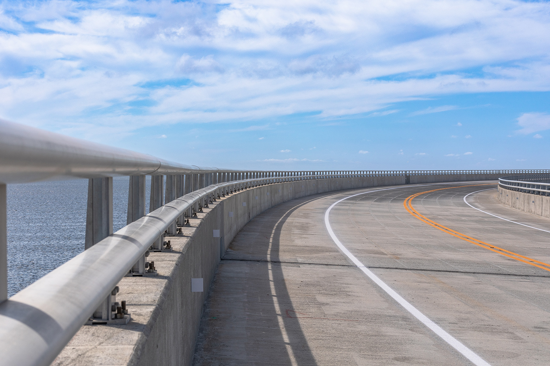
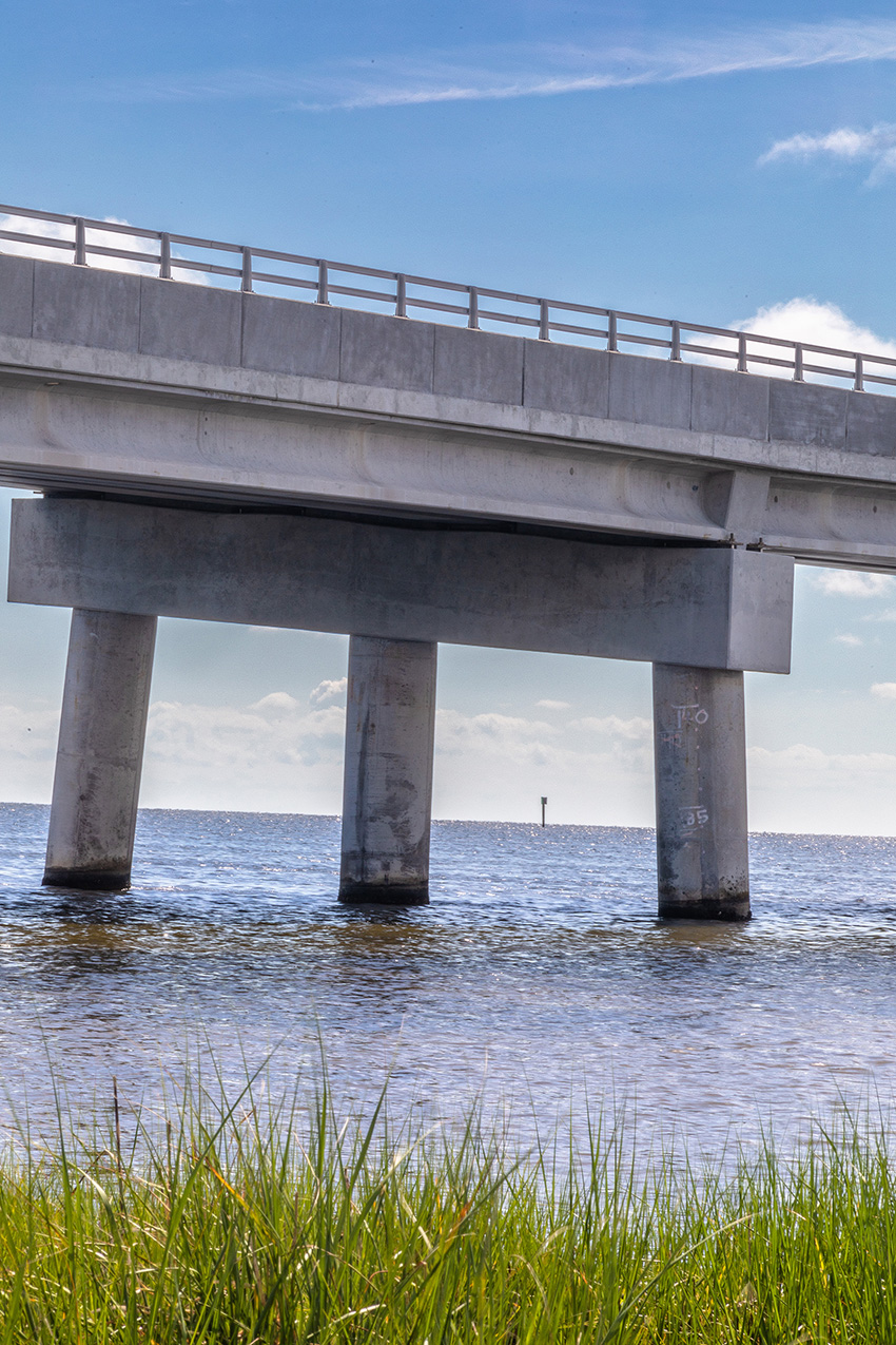
A typical main bridge roadway section includes two 12 ft travel lanes and two 8 ft shoulders. The 5 ft tall bicycle-safe barriers consist of a 3 ft tall concrete parapet topped by two metal rails. The total bridge width is 42 ft, 7 in. Four girders were constructed throughout the main bridge typical section. The tangent section of the main bridge pushed the top flange of the exterior girder to the outside edge of the deck via the edge girder system, which meant overhang falsework was not needed and deck construction could go faster.
The design-build team chose precast concrete for the piles, girders, and deck panels. Cast-in-place concrete was used for the interior and end bent caps, deck, and barriers. The final superstructure design of each section consists of five elements. The south and north transition spans are 60 ft long, with 24 in. prestressed concrete cored slabs, with a 6 in. (minimum) concrete-wearing surface. The span lengths for the south curve main bridge are 97 ft, 3 in., with 45 in. Florida I-Beams and 5 in. precast deck panels. The tangent main bridge has span lengths of 137 ft and features 72 in. Florida I-Beams made of 5.5 in. CIP concrete and 5 in. precast deck panels.
Finally, the north curve main bridge has span lengths of 135 ft, 9.5 in., with similar Florida I-beams and precast deck panels.
For the substructure, the south and north transition spans are CIP concrete bent caps with five 30 in. square prestressed concrete piles. The main bridge also has CIP concrete bent caps, with three 54 in. diameter prestressed cylinder piles.
The existing water depth in Pamlico Sound varies between 2 ft and 4 ft along the bridge’s alignment, which is an ideal depth and environment for submerged aquatic vegetation. Because three species of protected seagrass can be found in the sound, the work trestles for the project were open-grated to maximize sunlight to the underlying vegetation. In addition, the project team conducted a shade impact study and monitored the site before and after construction.
More than 5,000 sq ft of submerged aquatic vegetation under the structure were transplanted in a separate project.
Permitting
Three Oaks produced the permit application packages and provided environmental compliance for this project. Given the environmentally sensitive coastal zone, high visibility, large volumes of tourist traffic, and the number of federally protected species in the area, the permitting process required multiple meetings with various regulatory agencies and meticulous coordination with the construction team.
Three Oaks also developed an environmental compliance management plan that provided easy-to-reference guidance on the pertinent project commitments and permit conditions.
Utilities
Utility relocation proved to be especially challenging for the project team. The new structure carries existing utilities between the girders and under the deck, removing aerial lines from poles that stood just yards away from the ocean.
For utility relocation — temporary and permanent — RK&K worked with Cape Hatteras Electric Cooperative, Lumen (formerly CenturyLink), and Spectrum. CHEC, for example, moved its electrical lines and encased them in a stainless steel hanger system designed to withstand the ocean’s corrosive forces.
For utility relocation — temporary and permanent — RK&K worked with Cape Hatteras Electric Cooperative, Lumen (formerly CenturyLink), and Spectrum. CHEC, for example, moved its electrical lines and encased them in a stainless steel hanger system designed to withstand the ocean’s corrosive forces.
The utilities team also collaborated to design around a major joint-use transmission pole adjacent to the roundabout, saving months of relocation work.
Hydraulics
The roadway design provided two lanes from the existing NC 12 north of Laura Lane to the existing NC 12 approximately 1.8 mi north of the Pea Island National Wildlife Refuge’s southern boundary with Rodanthe. The horizontal alignment accommodated a 40 mph design speed on the southern portion of the project, through the roundabout, and to the southern terminus of the bridge. A 60 mph speed is posted for the remainder of the project, including the bridge.
One of the most difficult aspects of the roadway drainage design involved the bridge’s vertical grade. Because water could not run into the travel lanes, the drainage system was restricted to the 8 ft wide shoulders. However, much of the bridge’s vertical grade was flat, therefore, draining water would reach the shoulders without any system to direct it to release points. Because the standard practice in North Carolina calls for deck drains or scuppers to release that drainage, the placement of the deck drains became a major issue.
To resolve this problem, the design team consulted Hydraulic Engineering Circular 21, Design of Bridge Deck Drainage, May 1993, specifically Chapter 9, which details flat bridges. The project team used standard inputs — such as pavement width and slope, design spread, time of concentration, intensity, and the runoff coefficient — to determine the deck drain spacing. In areas of superelevation transition, 6 ft spacing was used regardless of calculations, which was the closest spacing possible.
At other locations, the spacing and number of deck drains were determined based on the required perimeter. Safety factors of a 30% loss of perimeter due to placement next to the barrier and a 7 ft shoulder were used.
Quite often for bridge design, the deck drain spacing is calculated at more than 125 ft. However, for this bridge, that was deemed excessive. Therefore, bridge deck drains in full superelevation were spaced at 25 ft and in normal crown sections at 50 ft. This doubled or tripled the number of deck drains that NCDOT required. As an additional check, the design-build team used the weir equation to verify the flow each deck drain could accommodate. NCDOT requires that storm drain systems take into account a 10-year storm event.
Assuming a deck drain blockage of 50% due to debris, the deck drains designed can accommodate a 50-year storm.
In the end, 502 deck drains were installed along the flat portion of the bridge.
Coastal modeling
INTERA provided the bridge hydraulic report for the project. Previous hydraulic models, reports, and data provided by INTERA helped NCDOT determine the design parameters: The low chord elevation had to be 17 ft above mean sea level, the scour elevation for the transition spans substructure had to be -30 ft, and the scour elevation for the main bridge substructure had to be -52 ft.
INTERA’s report supplied the scour and wave-force calculations as well as the end bent protection design. The local scour at the bridge interior bents was computed in accordance with NCDOT policy; HEC-18, Evaluating Scour at Bridges, Fifth Edition; and the application of Sheppard’s pier scour equations. In addition, scour at the end bents was calculated to determine the size and extent of riprap required. Wave force calculations were provided for superstructure transition spans below elevation 17 ft and for all substructure elements. The water-surface elevations, flow velocities, and wave forces were made available to the project team for the foundation and structure design.
Geotechnical
This project also included complex geotechnical exploration challenges for drilling and testing in the Pamlico Sound, including shallow water depths, cold and windy weather conditions, and environmentally sensitive conditions such as submerged aquatic vegetation on the bottom of Pamlico Sound along the alignment of the bridge.
NCDOT’s geotechnical unit contracted CATLIN Engineers and Scientists and Mid-Atlantic Drilling to perform soil test borings with standard penetration testing and cone penetration testing on an approximately 300 ft spacing along the bridge alignment. The firm used drill rigs and CPT rigs mounted on shallow draft jack-up barges for the tests. Testing could be conducted at shallow depths with the drill rigs, thus minimizing contact with the submerged aquatic vegetation in Pamlico Sound.
All but two borings were provided by NCDOT. To satisfy the request for proposal requirement for driven piles, Wood performed boring in the marsh area and in the sound near the northern shoreline along the bridge alignment using Mid-Atlantic’s drill rig mounted on a swamp buggy carrier that minimized ground disturbance along the marsh and sound bottom.
The typical subsurface profile along the bridge alignment consists of layers of very loose to medium dense sands and silty sands to an approximate elevation of -40 ft. Beneath this is an upper dense to very dense sand/silty sand layer that exists from an approximate elevation of -40 ft to -65 ft. In turn, the upper dense sand/silty sand is underlain by layers of very loose to loose sands and very soft to firm sandy silts, which extend to a lower dense to very dense sand layer that exists at elevations ranging from -130 ft to -150 ft.
The geotechnical design of this project was challenging due to the main bridge structure’s -52 ft scour elevation and the presence of the upper dense sand/silty sand layer from approximately -40 ft to -65 ft. To satisfy the lateral and axial requirements, deep foundations extend into the dense lower sand layer at elevations ranging from -125 ft to -150 ft. To satisfy the lateral, axial, and large unsupported lengths (bottom of cap to scour elevation), large foundation elements were used.
The Rodanthe Bridge uses precast 54 in. diameter concrete cylinder piles throughout the length of the main bridge. The project team selected this foundation for its stiffness to meet the structural and geotechnical resistance demands as well as decrease the number of piles required for each bent. Waterline footings were not necessary because these piles also extended to the bottom of the cap.
The axial analysis (accounting for a scour elevation of -52 ft) was performed using Ensoft’s APILE software. The required driving resistance to satisfy the axial and scour resistances was determined using pile driving analysis testing and RFP parameters. RK&K used FB-MultiPier for the lateral analysis. Wood provided soil parameters for the FB-MultiPier models along the bridge and reviewed the model results to set the minimum tip elevation based on the analysis. Wood also confirmed the piles achieved fixity.
The total number of 54 in. diameter precast concrete cylinder piles is 294 with a total length of installed driven piles of approximately 41,500 linear ft. The transition spans consist of 30 in. square precast prestressed concrete piles. The total length of 30 in. pile installed was about 4,500 linear ft. The concrete piles (30 in. and 54 in.) were driven between 80 ft to 140 ft deep into the bottom of Pamlico Sound.
Structure
Another challenge was designing a bridge with vastly different design conditions. For one condition, the bridge had to be flexible and durable in just 2 ft of water, and for the other condition, it had to be strong and resilient in up to 52 ft of water — which meant, in effect, designing two bridges. In addition to meeting the American Association of State Highway and Transportation Officials’ Load and Resistance Factor Design bridge design specifications, the RFP mandated three additional limit states: LRFD loading under the most severe scour, extreme event vessel collision force with associated scour, and stability checks during a super flood and the most severe scour.
The structural design included several other significant requirements, including a wind speed of 105 mph, a potential vessel collision force of 200 kips, a coastal limit state with wave forces (velocity 9.9 fps) accounted for below elevation 17 ft, future utility loads, and a design scour elevation of -52 ft as well as several corrosion-protection measures.
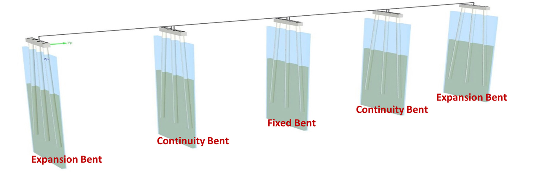
The design model comprised a four-span continuous superstructure unit with one fixed bent in the center and four expansion/continuity bents. The superstructure loads were transferred to the substructure via shear keys at the expansion bents. The stainless steel rebar had a design yield strength of 60 ksi, and the concrete strengths for the various components were between 4.5 ksi for the CIP concrete deck and 10 ksi for the prestressed concrete piles and 45 in. Florida I-Beams.
Construction
The team collaborated on what it called an “advancing rail system,” or leap-frog technique, to construct this singular structure. The shallow water, 100 ft right of way, submerged aquatic vegetation, dense sand layers, and windy weather along the coast were all obstacles the team encountered and overcame. Flatiron and RK&K optimized the superstructure design by choosing a four-girder typical section, which then determined the maximum possible span lengths.
The substructure was derived by an iterative process. Building the bridge using this innovative technique and constructing the bridge from the north and south headings (the south heading had a head start) accelerated the project schedule and mitigated delays. The advancing rail system fit within the provided right of way, minimized impacts to the submerged aquatic vegetation, and streamlined the construction flow.
Construction began in November 2018 with the assembly of the advancing rail system at the south heading in Rodanthe. Construction at the north heading within the Pea Island National Wildlife Refuge began in March 2019. The two headings met at span 76 in November 2021, and the bridge opened to traffic on July 28, 2022.
The Jug Handle Bridge is North Carolina’s ninth-longest bridge. This uniquely curved structure will ensure that those who travel on this part of NC 12 have access to a resilient and stable structure that can stand against the ravages of nature.
David B. Peterson, P.E., F.ASCE, is the director of structures at RK&K, in Raleigh, North Carolina.
Project credits
Owner: North Carolina Department of Transportation
Engineer of record: RK&K, Raleigh, North Carolina
Geotechnical: Wood, Durham, North Carolina
Coastal hydraulics/modeling: INTERA, Gainesville, Florida
Contractor: Flatiron Constructors Inc., Morrisville, North Carolina
Fabricator: Coastal Precast Systems, Chesapeake, Virginia
Gantries: DEAL S.r.l., Pozzuolo del Friuli, Italy
Right of way: Right of Way Consultants LLC, Winston-Salem, North Carolina
Soil testing: CATLIN Engineers and Scientists, Mid-Atlantic Drilling, both Wilmington, North Carolina
This article first appeared in the January/February 2023 issue of Civil Engineering as “Coastal Crossing.”