By Andrea Soligon, P.E., S.E., CEng, Ing, M.ASCE, Jeng Neo, CEng, MIStructE, and Xiaonian Duan, Ph.D., CEng
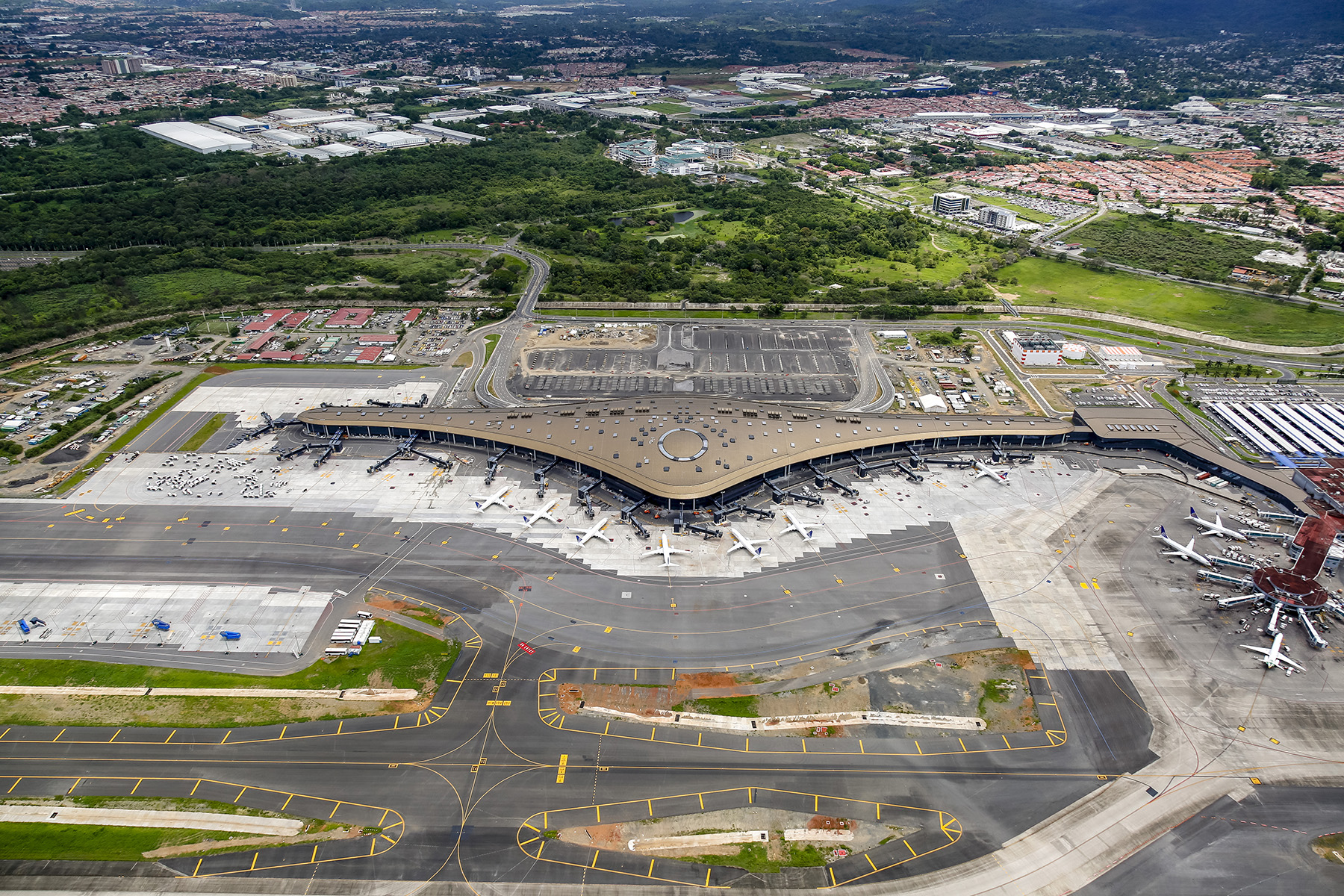
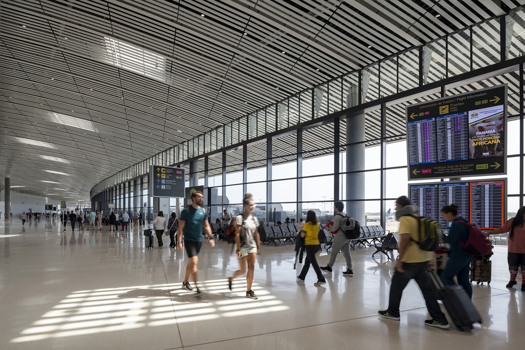
The new Terminal 2 at Tocumen International Airport in Panama City adds 20 gates to those of the existing Terminal 1 to achieve an estimated total capacity of 25 million passengers per year, thus solidifying the country’s status as the Hub of the Americas. Designed using state-of-the art performance-based seismic design methodology and an innovative energy-dissipating column fuse detail, the terminal fulfills its mission as a seismic-resilient essential facility.
Located in Panama City, the capital of the Republic of Panama, Tocumen International Airport is one of the busiest airports in Central America. To meet the ever-increasing demand for business, logistics, and tourism in the country, in 2012 the owner, Aeropuerto Internacional de Tocumen S.A., launched an international design competition to award a design-build contract for an airport expansion.
Based on a design by Foster + Partners, the global construction firm OEC was selected. OEC subsequently retained Foster + Partners to provide full structural engineering services to be delivered in an integrated manner with Foster + Partners’ in-house architectural and mechanical, electrical, and plumbing teams.
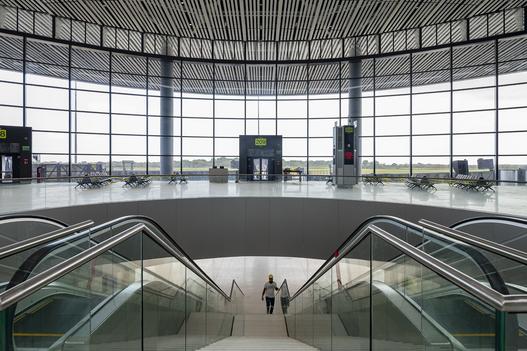
The new terminal is shaped like an aircraft wing with a gross area of about 116,000 sq m. It is 660 m long, up to 162 m wide in plan, and up to 26 m tall. The ground level accommodates arrivals and the baggage hall. Departures are on the second level, and the food courts, airline lounges, offices, and back-of-house operations are on the third and fourth levels in the main concourse.
Foster + Partners also designed a 200 m long connector building that links the existing terminal to the new one to form a single airport complex, an energy center, and several other ancillary buildings.
Although the new terminal is on a site that was previously empty, extensive earthwork was required to consolidate the site’s soft soils. In addition, a shallow riverbed that passed through the footprint of the new construction was diverted from its original alignment.
Performance-based seismic design
Panama is in a seismically active region, and seismic considerations governed the structural design. The owner’s brief classified the new terminal as an essential facility; therefore, its construction required an enhanced seismic design approach, one that went beyond the scope of conventional prescriptive seismic design found in local and international building codes.
The design had to target operational continuity and limit structural and nonstructural damage following moderate and severe earthquakes, respectively. To achieve this, Foster + Partners adopted state-of-the-art performance-based seismic design methodology with the following performance objectives:
- Operational: after an occasional earthquake with a return period of 72 years (50% probability of exceedance in 50 years).
- Immediate occupancy: after a rare earthquake with a return period of 475 years (10% probability of exceedance in 50 years).
- Life safety: after maximum considered earthquake with a return period of 2,475 years (2% probability of exceedance in 50 years).
URS Corp. (since acquired by AECOM) performed a probabilistic seismic hazard assessment to generate site-specific horizontal and vertical response spectra for 72-, 475-, and 2,475-year return periods as well as suites of seven sets of horizontal and vertical ground motions spectrally matched to the 2,475-year spectra. Variable soil conditions across the length of the site meant that the design team had to apply different spectra and ground motions.
The seismic design category was D, in accordance with Panama Building Code REP and ASCE 7, Minimum Design Loads and Associated Criteria for Buildings and Other Structures (ASCE/SEI 7-10), which was based on the risk category and equivalent SDS and SD1 spectral response acceleration parameters.
The PBSD was implemented largely in accordance with Pacific Earthquake Engineering Research Center’s Tall Buildings Initiative Guidelines for Performance-Based Seismic Design of Tall Buildings, making the new terminal one of the first international applications of these guidelines for a low-rise structure.
Actions on members of the seismic force-resisting system were classified as either deformation controlled — with demand parameters evaluated based on deformation limits set in ASCE 41, Seismic Evaluation and Retrofit of Existing Buildings — or critical and noncritical force controlled, per PEER’s Guidelines.
Seismic demand for critical force-controlled actions — such as shear in concrete walls and frames, flexure, axial force, and shear and torsion in the primary members of the steel roof — was taken as 1.5 times the average demand from a suite of seven ground motion time histories.
Structural members were then designed and detailed in accordance with the American Concrete Institute’s Building Code Requirements for Structural Concrete (ACI 318-11) and Commentary (ACI 318R-11) and the American Institute of Steel Construction’s Specification for Structural Steel Buildings (ANSI/AISC 360-10) standards. The structural design team evaluated the members by applying strength reduction factors and nominal or expected material properties, per PEER’s Guidelines.
Conventional prescriptive designs require only linear modal response-spectrum analyses, but the structural design team opted to perform advanced inelastic structural analyses of the seismic force-resisting system, including nonlinear static pushover and nonlinear response history analyses.
As an essential part of PBSD, an independent peer review was conducted to review the basis of design, seismic hazards, structural analyses, calculations, and drawings.
Despite the additional complexities due to the PBSD approach, the project was fast-tracked, and construction of the foundations began only five months after project kickoff. The structural design team delivered construction documents packages on a biweekly basis, per the construction schedule, while also reviewing shop drawings and submittals from packages previously released.
Close collaboration and constant communication among the design-build contractor, the structural team, and the wider design team were essential to successfully advance concurrent design and construction activities.
When construction of the primary structure was largely complete, within the original fast-track schedule, changes in the owner’s scope led to revisions in the design brief and the addition of other ancillary buildings, which extended the completion time of the overall project.
Structural systems
The terminal is separated into five independent structures (named, from east to west, zones 1A, 1B, 3, 2B, and 2A) via four seismic joints to mitigate thermal expansion effects and control seismic horizontal irregularities. While the types of structural systems vary among the zones, the design is unified by an architecturally exposed structural steel roof that varies in curvature along the length of the terminal. Its bays are up to 18 m by 46 m.
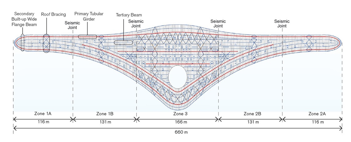
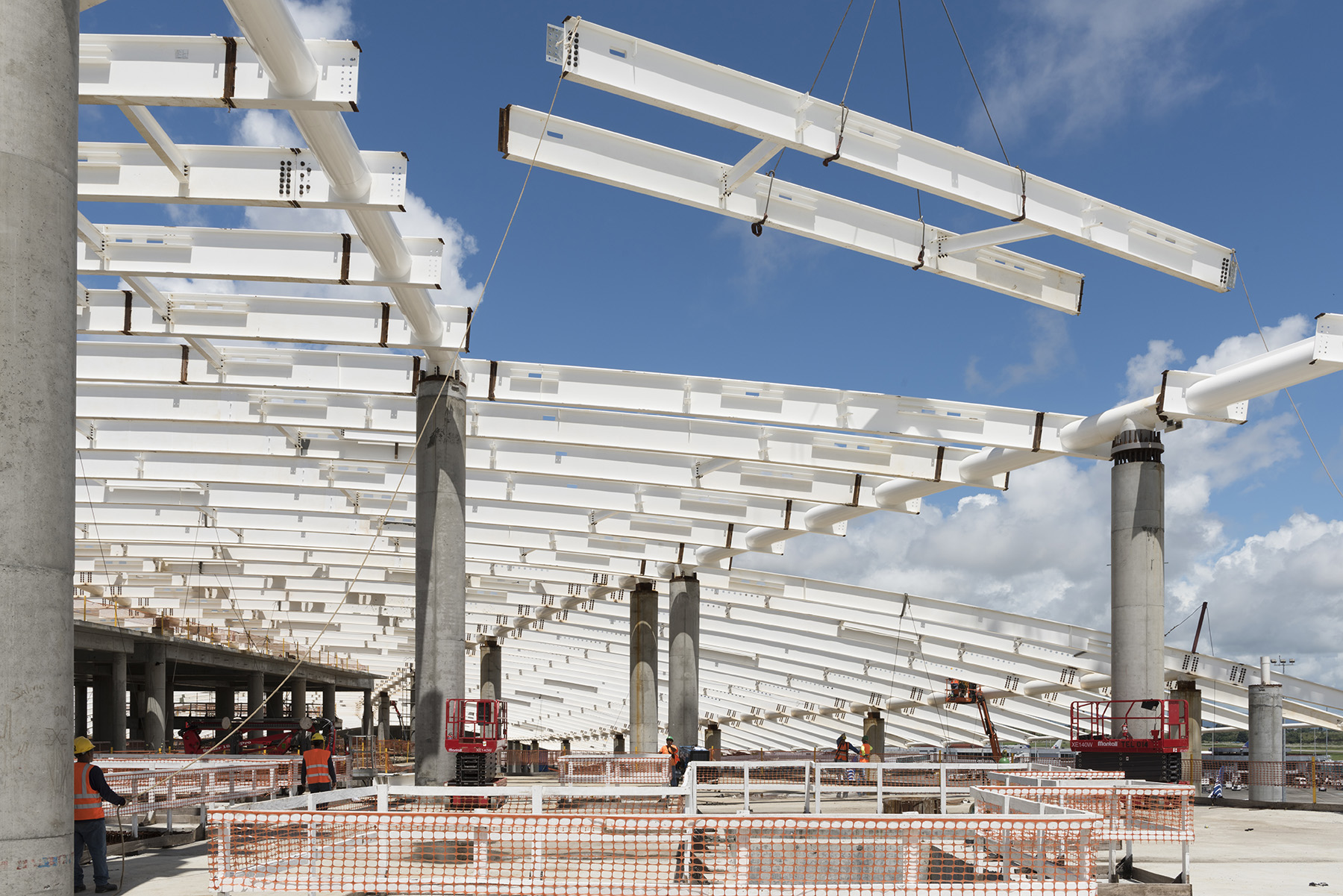
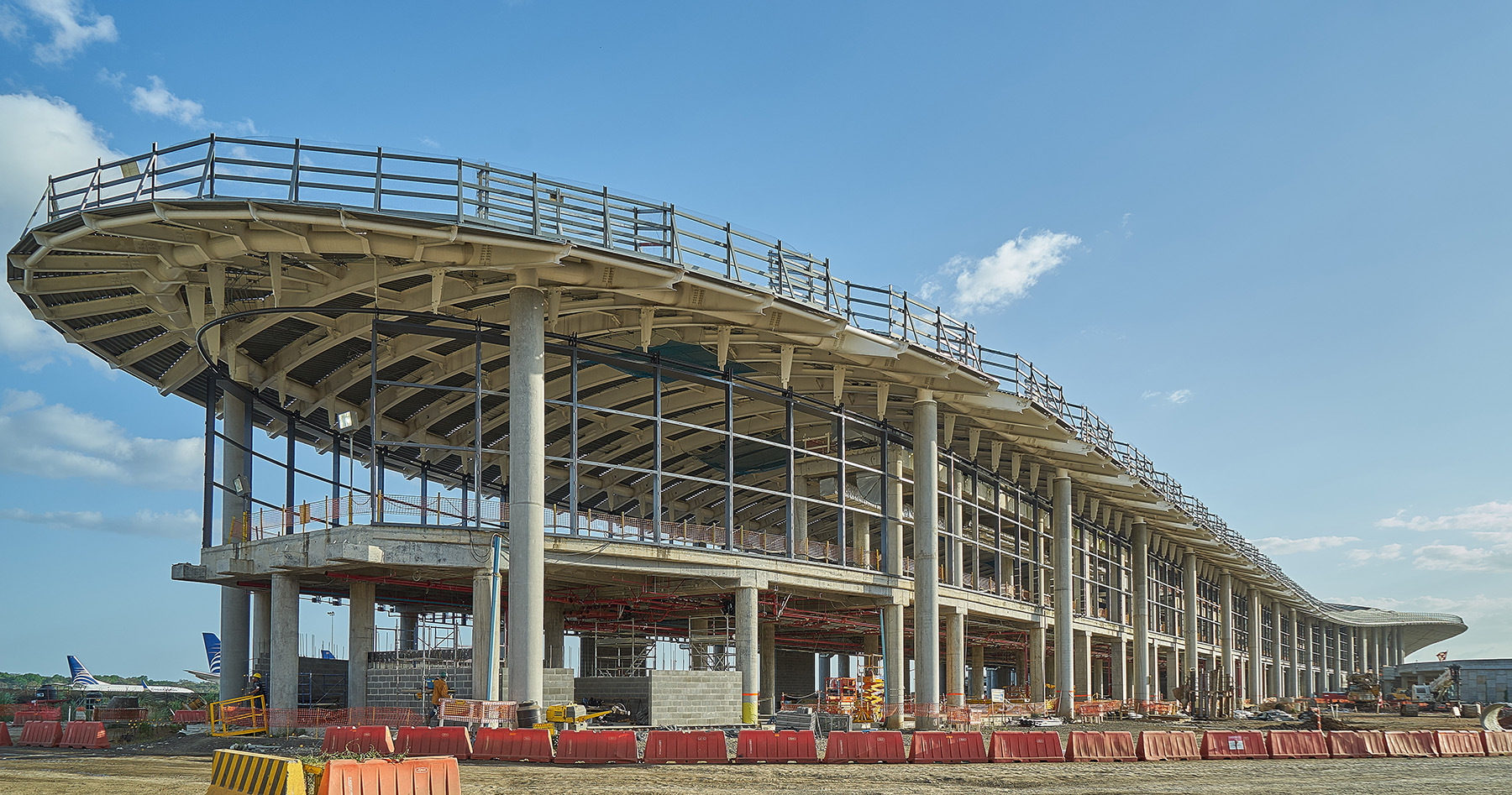
The architectural design intent expresses the roof’s transverse secondary steel beams, which do not frame directly onto the roof columns and were made deeper than the longitudinal primary girders. The bottom flanges of the secondary beams are visible and integrated with the ceiling slats. The primary girders are above the ceiling, making it appear as if the roof floats over its supports. The rest of the structure is constructed in concrete — the material of choice in Panama.
Each of zone 1A and 2A, at the tips of the terminal, comprises two independent structures: a single-story concrete superstructure with a partial mezzanine and a 16 m tall steel roof supported on perimeter concrete columns detached from the concrete superstructure. The lateral force-resisting system for the superstructure comprises special reinforced-concrete moment frames in two orthogonal directions.
The steel roof structure and the perimeter concrete columns also act as moment frames, including in the transverse direction due to the high torsional stiffness of the tubular primary girders.
Each of the other zones — 1B, 3, and 2B — consists of a single structure in which selected internal columns are extended upward to provide additional support to the roof, which becomes progressively wider toward the center of the terminal. Special reinforced-concrete moment frames, together with the reinforced-concrete perimeter columns and steel roof, form the seismic force-resisting system.
In zone 3 — the largest zone, measuring 165 m by up to 165 m in plan — special reinforced-concrete shear walls were introduced in the concrete superstructure in addition to the special concrete moment frames to resist the higher seismic demand and control drift.
Simpson Gumpertz & Heger Inc., in collaboration with Foster + Partners, performed the nonlinear response history analyses and implemented the construction documents for zone 3’s steel roof.
Gravity framing generally consists of locally manufactured precast, prestressed concrete double-tee decks that span between 12 m and 18 m onto cast-in-place, conventionally reinforced beams, or unbonded posttensioned beams for spans exceeding 18 m. The beams and double tees are capped with a CIP concrete diaphragm that is designed to act compositely with the precast tees for gravity loads.
Precast decks were selected to accelerate the erection schedule, and they proved to be an efficient system, enabling long, column-free spans in the main concourse while minimizing seismic mass.
The terminal sits on several layers of fluvial sediments of soft, medium, and stiff consistency overlaid by fill material. An extensive geotechnical investigation with more than 80 boreholes indicated significant variability in the ground conditions across all zones of the site. Sound rock was found between 9 m and 23 m below the existing grade level.
The foundation system is composed of CIP drilled straight shaft piles socketed into rock. Pile diameters are 1.37 m and 0.9 m, with socket length varying between 6 m and 9 m.
Building columns are typically supported by individual piles, with a grillage of grade beams tying the pile caps and providing base fixity to the superstructure. Static and dynamic pile load testing were performed in the field using bidirectional Osterberg Cell and Pile Dynamics’ Pile Driving Analyzer system to validate the design pile geotechnical capacities.
Structural steel roof design and construction
The roof structure consists of 75 mm deep, unfilled metal decking on curved, built-up, wide-flange secondary beams placed at 3 m on center. The beams span between 20 m and 46 m in the transverse direction. The secondary beams are supported on steel tubular primary girders that span 18 m in the longitudinal direction between concrete columns. Along the perimeter, the secondary beams cantilever from the primary girder line by up to 16 m to form canopies on either side of the terminal.
Tertiary beams provide lateral restraint to the long-span secondary beams against compression buckling and lateral-torsional buckling under flexure. The beams deliver restraint forces to separate in-plane bracing systems within each zone of the roof structure. The roof deck is designed and detailed for diaphragm action.
In the central part of the terminal, where the roof spans up to 46 m, sensitivity analyses indicated that vertical seismic shaking effects were significant; therefore, the vertical degree of freedom of the mass of the roof was excited, and vertical ground motions were explicitly modeled in the nonlinear response history analyses rather than using the conventional code seismic vertical component (Ev) of 0.2SDS x dead load.
The transition between the concrete roof column and tubular primary girders comprises a tubular steel column stub-welded to a base plate, which is fixed onto the top of the reinforced-concrete column. The welds were specified as demand-critical complete joint-penetration welds, and the connection strength at the vertical to horizontal tubular steel members was checked as a thickened chord T-joint, per the guidelines in the American Petroleum Institute’s Recommended Practice for Planning, Designing and Constructing Fixed Offshore Platforms — Working Stress Design (2000). Safety factors were modified to be consistent with load resistance and factor design force level.
The structural design team specified that a steel template of the actual base plate be used to align the vertical reinforcement of the concrete columns. This was done so that the columns could be cast up to the grout zone under the base plate with the reinforcing bars, which act as anchor rods, in the correct alignment to match predrilled holes in the base plate.
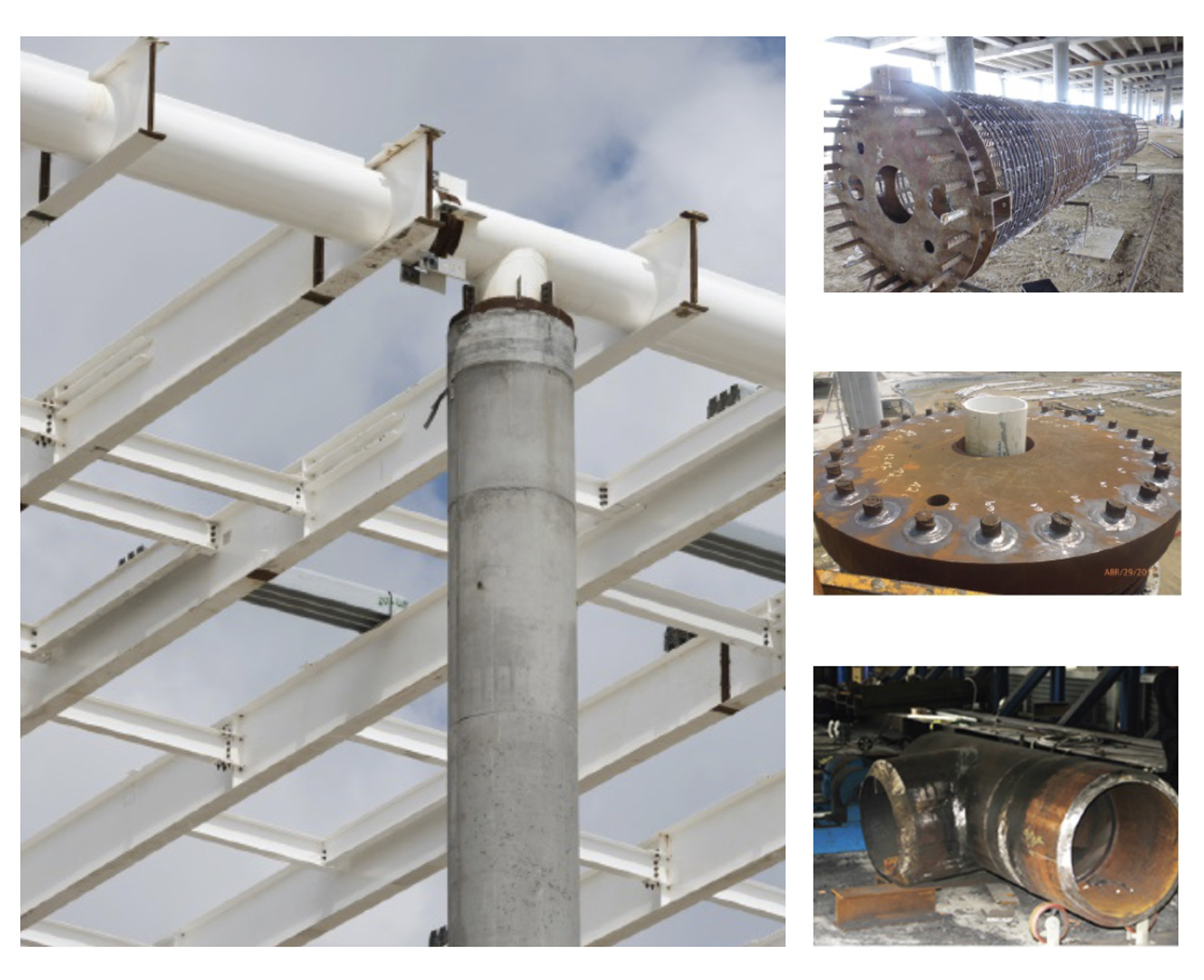
The base plate was then lowered from the top, the grout zone was filled via a grout hole in the base plate, and the connection between reinforcing bars and base plate was made via field partial joint penetration welds. This method permits moment continuity from the roof structure into the concrete columns.
The PJP welds were qualified by tests in accordance with the American Welding Society’s AWS D1.4 Structural Welding Code—Reinforcing Steel. Lateral shear is transferred into the concrete columns via short tubular shear lugs welded to the underside of the base plate.
Because the steel column stubs and concrete roof columns are architecturally exposed, rainwater pipes were carefully detailed to be embedded within the perimeter roof columns. To facilitate erection, the tubular primary girders were designed and fabricated with short secondary beam stubs on both sides, ready to be field-spliced with the secondary beams, which were erected in pairs.
The steelwork was fabricated under strict shop-quality control requirements in South Korea and shipped to Panama, where it was erected by a team of local and international erectors and AWS-qualified welders. The steel members were shop-coated with a robust corrosion protection system, and connection zones were field-painted following erection. Thousands of additional quality assurance tests were then performed by the special inspection team.
Members of the structural engineering staff also relocated to Panama to perform structural observations and facilitate communication with the contractor during the critical phases of construction.
Innovative fuse detail
The roof structure is composed of tubular — rather than wide-flange — members with a nonorthogonal geometry and an unconventional, noncode-prescribed framing configuration. This meant the structural design team could not specify prequalified connections for special steel moment frames in accordance with Prequalified Connections for Special and Intermediate Steel Moment Frames for Seismic Applications (AISC 358) at the roof beam to column joints.
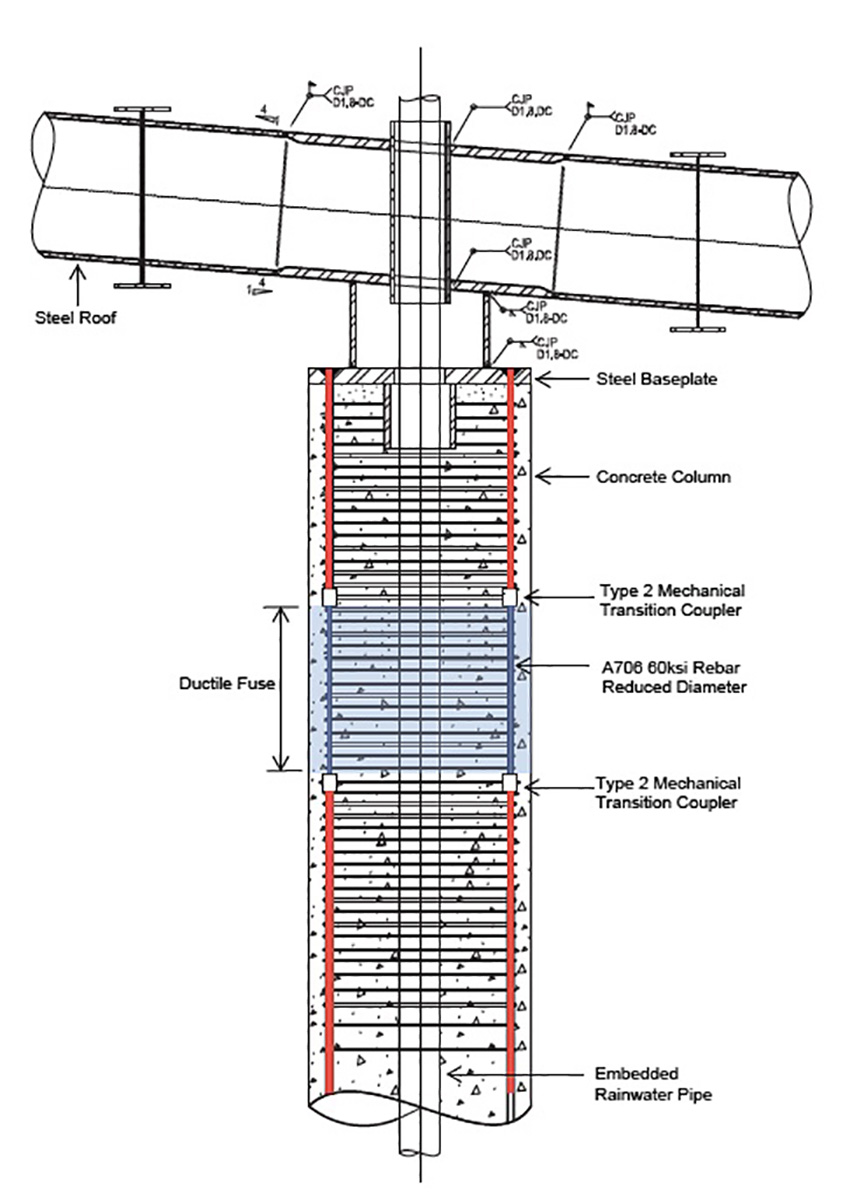
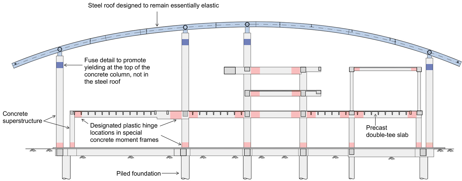
Because of the roof’s limited ductility, Foster + Partners developed an innovative fuse detail at the top of the concrete columns so that energy dissipation under strong seismic shaking would happen exclusively in the concrete structure.
In this scenario, the columns’ vertical-reinforcing bars are locally reduced in size to create a weakened zone between strong segments. This weakened zone becomes the area in which ductile plastic rotation and energy dissipation can occur.
The fuse detail consists of a ring of smaller-diameter vertical-reinforcing bars spliced by ACI 318 type 2 transition mechanical couplers to larger-diameter reinforcing bars above and below. This forms a reinforced-concrete equivalent of the steel special moment frame’s reduced beam section connection. Closely spaced transverse shear reinforcement provides confinement for the fuse region.
By performing nonlinear response history and pushover seismic analyses, the flexural strength of the weakened fuse segment was tuned to capacity-protect the roof and limit the maximum seismic force that can be transferred to the roof. This approach enabled the roof structure to be designed as a critical force-controlled element that remains essentially elastic under MCE shaking.
Selected gates of Terminal 2 were initially opened in 2019 to celebrate World Youth Day, and the rest of the terminal was opened in summer 2022. The airport expansion brings a world-class terminal to the country, welcoming visitors from around the world.
Andrea Soligon, P.E., S.E., CEng, Ing, M.ASCE, is a partner, Jeng Neo, CEng, MIStructE, is an associate partner, and Xiaonian Duan, Ph.D., CEng, is a partner in Foster + Partners’ structural engineering group based in London.
Project credits
Owner: Aeropuerto Internacional de Tocumen S.A., Panama City
Design-build contractor: Odebrecht Engineering and Construction, Panama City
Design structural engineer; architect; and mechanical, electrical, and plumbing engineer: Foster + Partners, London
Structural engineer of record: Ing. O.M. Ramirez & Asociados S.A., Balboa-Ancón, Panama
Specialist structural consultant: Simpson Gumpertz & Heger Inc., Oakland office
Architect of record: Mallol Arquitectos, Panama City
Seismic hazard consultant: URS Corp. (now part of AECOM), Los Angeles office
Geotechnical engineer: Ingenieros Geotécnicos S.A., Panama City
Civil engineer: T.Y. Lin International, Coral Gables, Florida, office
This article first appeared in the March/April 2023 issue of Civil Engineering as “Seismicity Shapes New Terminal.”