By Guoming Lin, Ph.D., P.E., G.E., D.GE, F.ASCE, Christopher Novack, P.E., Oliver Himbert, P.E., Brad Woodall, P.E., Daniel Peavy, P.E., M.ASCE, and Honor Hutton, P.E.
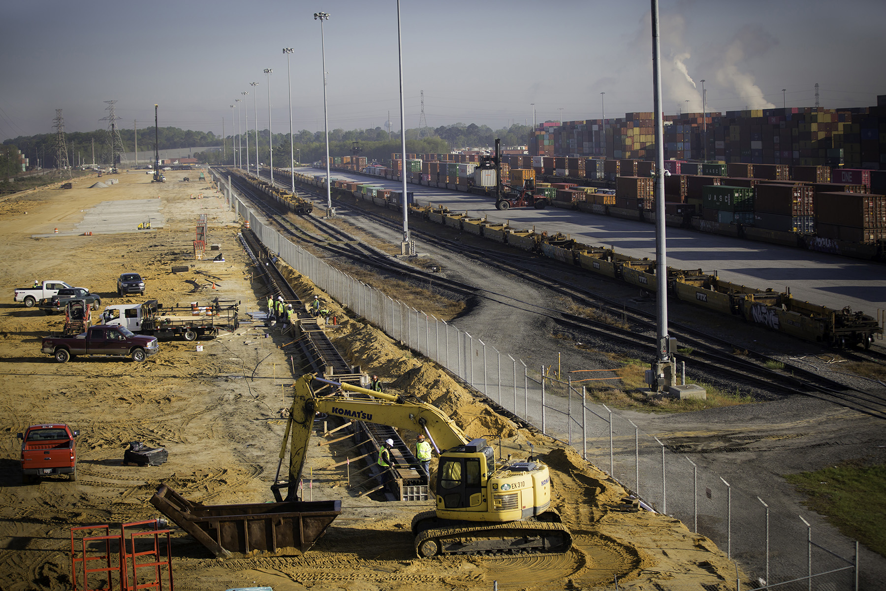
The Mason Mega Rail project provided ample room to expand a major shipping container terminal at Georgia’s Port of Savannah. But first the geotechnical engineers had to get the ground ready for new tracks and other facilities.
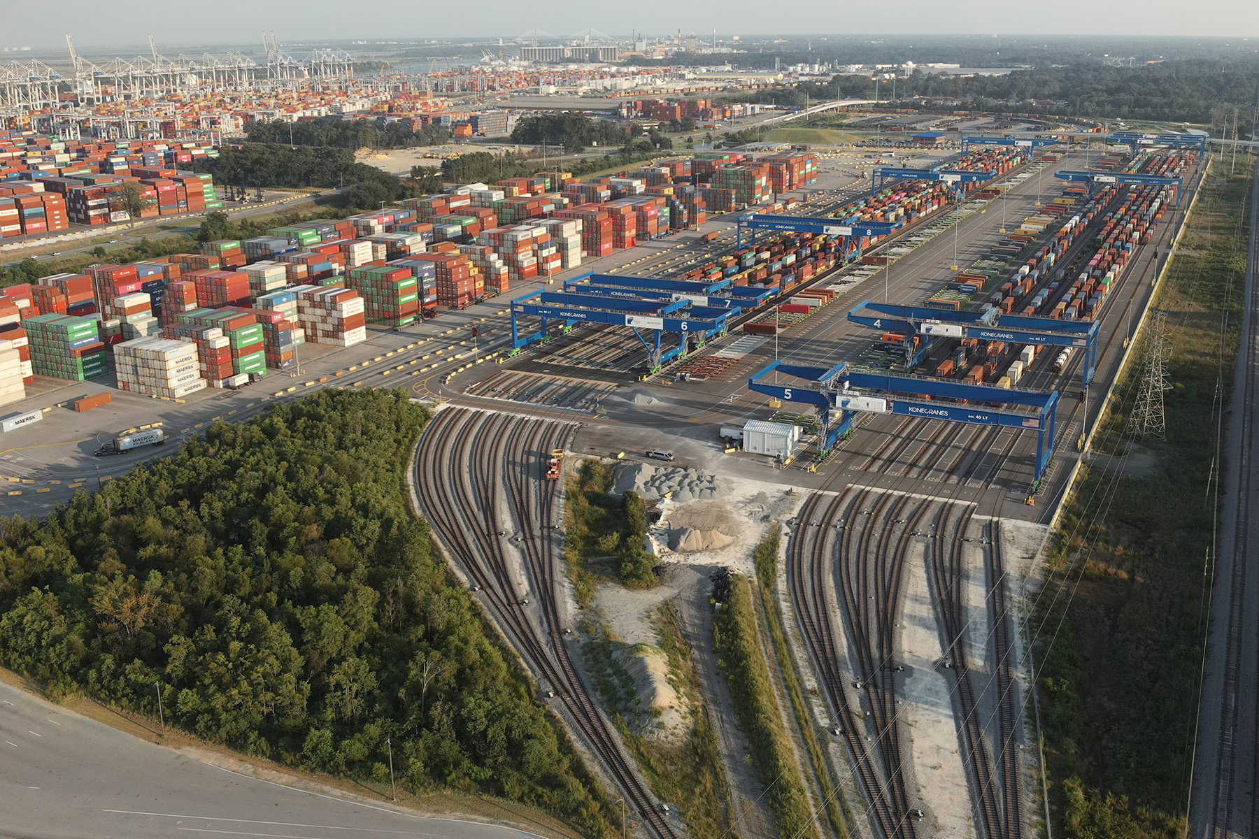
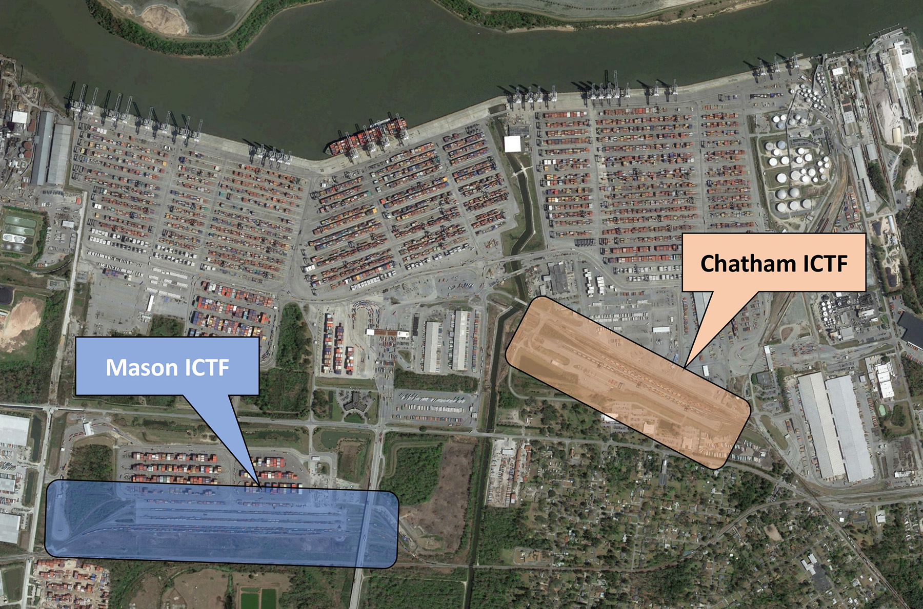
At 1,345 acres, the Garden City Terminal at Georgia’s Port of Savannah is the largest single-operator shipping container terminal in the United States. Originally, the facility included two rail yards on the north and south sides of a major waterway, the Pipemakers Canal. These two yards operated as separate facilities for different railroad companies: to the north was the Mason Intermodal Container Transfer Facility used by the Norfolk Southern Railway while to the south was the Chatham Intermodal Container Transfer Facility used by CSX Transportation.
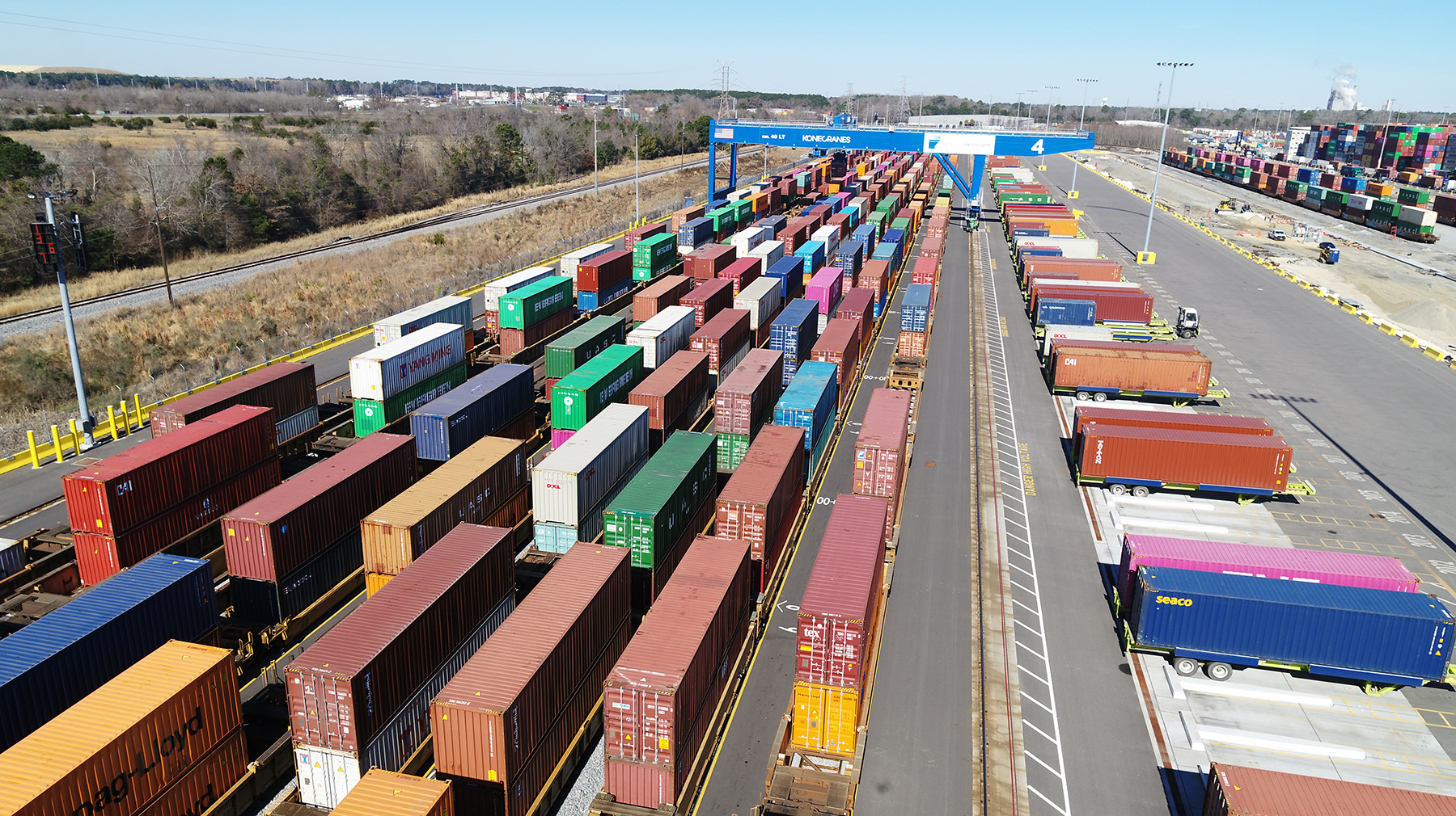
The recently completed Mason Mega Rail project was designed to connect the two yards by adding additional rail trackage, supported by rail-mounted gantry cranes, to increase the intermodal rail capacities and the overall throughput for standard shipping containers, known as twenty-foot equivalent units.
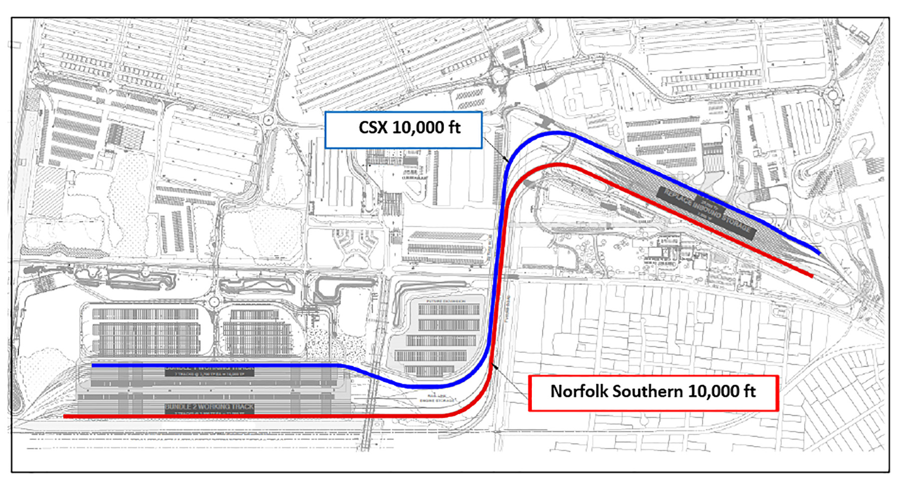
The connected rail facility created a 185-acre intermodal facility within the Garden City Terminal that serves Norfolk Southern and CSX simultaneously. This enables the two Class I railroads to assemble six 10,000 ft long unit trains at the terminal, doubling the rail capacity to more than 1 million annual lifts.
Furthermore, the newly connected rail tracks eliminated the need for six at-grade crossings in the nearby residential neighborhoods, which will reduce road blockages and enhance the quality of life for the surrounding Garden City community.
Triple tasks
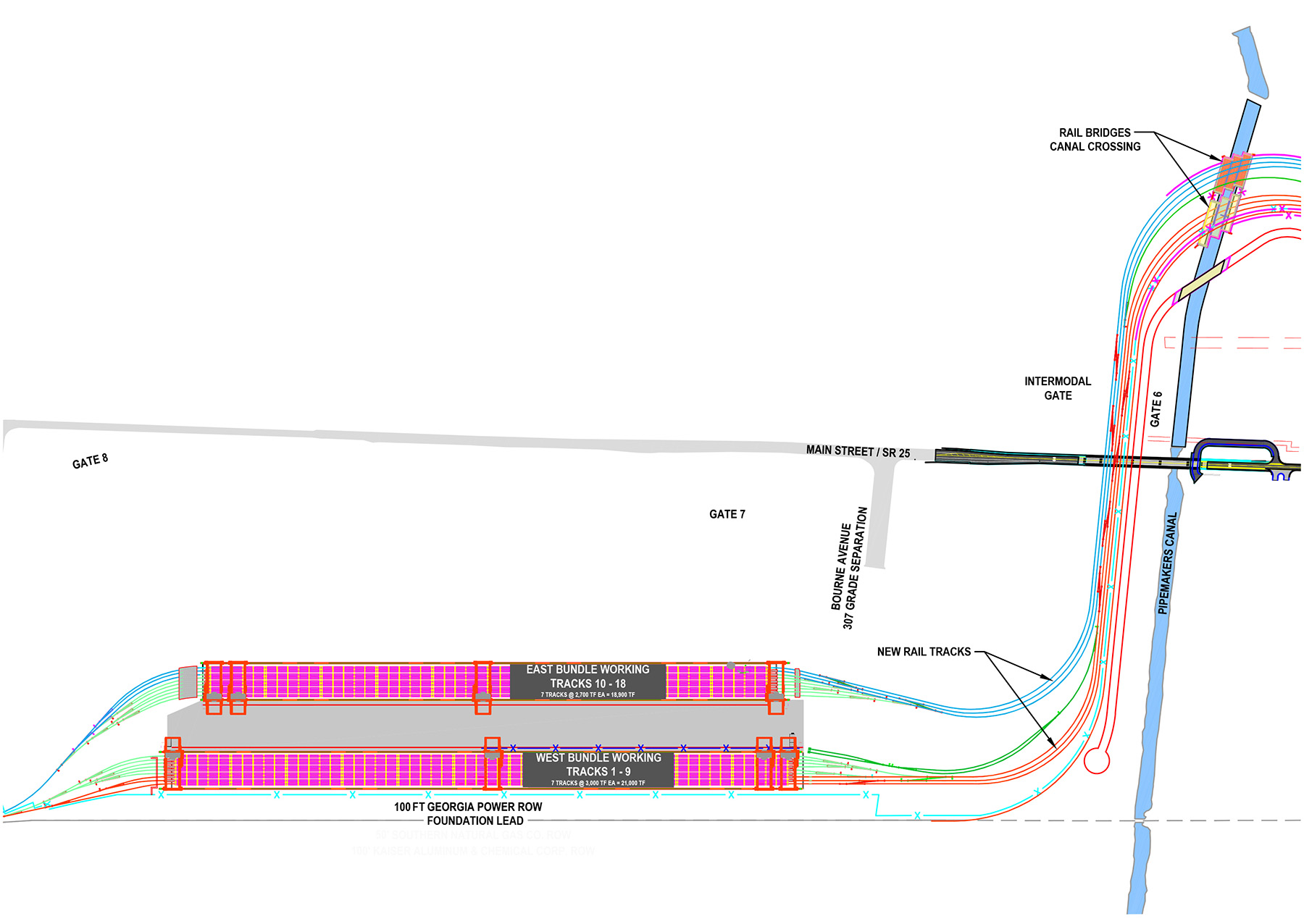
The project involved three major components: expanding the original Mason yard site by adding 18 tracks serviced by the new, fully electric gantry cranes, constructing eight new rail tracks along the north bank of the Pipemakers Canal, and erecting two new rail bridges to cross the canal and extend the new tracks into the Chatham yard site.
The area for the Mason yard expansion abuts a wetland that has very weak and highly variable soils. A majority of the alignment for the new tracks involved unregulated industrial landfill, and the areas along the banks of the canal were underlain by very soft marine clays that were highly compressible and posed the risk of large settlements and slope stability failure beneath the new rails.
Several ground improvement techniques were used to deal with these subsurface challenges. First, in the industrial landfill area, high-energy dynamic compaction was used to compress the upper 10-15 ft of the landfill material and to collapse any voids within the landfill. Targeted undercutting — the excavation of poor soils and replacement with better material — and geogrid reinforcement were then used to mitigate localized areas that remained unstable after the dynamic compaction.
Next, in the Mason yard expansion area, a stable subgrade was created by additional undercutting and geogrid reinforcement.
Low-energy dynamic compaction was used in the rest of the expansion area to compact the loose sands in the upper 5 ft. A retaining wall was constructed out of geocell-reinforced facing material. Various sizes of driven prestressed concrete piles were used to support the gantry crane runways and the bridges crossing the canal.
The embankment along the bridge approaches was improved using rigid inclusions, which are a ground improvement technique that uses stiff elements such as grout, concrete columns, or piles to reduce settlement. The loads are distributed to the rigid inclusions through a load transfer platform, and not through a rigidly connected pile cap as with conventional pile foundations.
In low-lying sections of the expansion area, where a high-fill embankment was required, soil surcharging with wick drains was used to preconsolidate the subgrade to reduce post-construction settlements for the rails and drainage structures.
Landfill site strengthening
The site for a majority of the rail tracks was an old, unregulated industrial landfill that had once been operated by a large paper mill. The subsurface exploration was performed using a combination of soil test borings, cone penetration test soundings, and test pits. Test pit excavation was the primary method to explore the landfill material.
The landfill had been created before the 1970s by unregulated dumping over a low-lying area on the bank of the Pipemakers Canal. The content of the landfill material was highly variable — from trash to construction debris mixed with soils, metal, wires, and a large number of logs and wood. The original ground surface consisted of 9-13 ft of landfill material capped with 1 ft of nonstructural fill. The native soil below the landfill debris was a thick layer of very soft clay-coastal marine deposits.
The new tracks had to be laid over ballast and a sub-ballast layer above a stable subgrade, all of which had to support a locomotive and cars weighing up to 2.3 million lb. To achieve this, the landfill material had to be compressed to reduce post-construction settlement and create that stable subgrade for track construction.
After compression, the densified landfill layer would distribute loads to the underlying very soft clays. The consolidation settlement of the very soft native soils would be caused primarily by the weight of the fill material and can be mitigated by adjusting and leveling the ballast layer as part of regular maintenance.
Dynamic compaction is a process in which a heavy tamper is repeatedly raised and dropped from a specified height to impact onto the ground surface, thereby transmitting high compaction energy into the soil mass. The depth of improvement depends on the tonnage and the height of the drop. The degree of improvement depends on the amount of energy applied per unit area. The tamper is raised and dropped by a single cable with a free spool hoisting drum.
The repeated impact on the ground by the tamper caused the formation of craters, which were then filled with a structural fill material prior to repeating the process. Relatively clean sands with less than 15% fines, along with broken pieces of construction debris, were specified as the structural fill for the craters.
The use of dynamic compaction on this project was somewhat unusual, as the process is typically used to densify loose sands but is considered unsuitable for sites with saturated clays. The rail track area was underlain by soft saturated clays below the landfill material. After initial heavy tamping resulted in dozens of craters, a large section in one area became “liquefied” — a grossly unstable state resembling a waterbed. The problem was exacerbated at that site by shallow groundwater at depths of 2-3 ft below grade and poor drainage.
Although the effectiveness of dynamic compaction was initially called into question, these challenges were overcome by cutting additional ditches to lower the groundwater table and filling the craters with relatively clean sands. Consequently, the ground conditions improved gradually and were restored to a stable condition in about two weeks.
Although a five-day waiting period was initially imposed for subsequent dynamic compaction work to allow the liquefied soils to regain strength, the problem did not recur, so the waiting period was lifted. The original liquefaction problem was attributed to specific conditions of groundwater and soil composition at the affected site.
After two rounds of high-energy dynamic compaction and filling of craters and one round of an ironing pass using low-energy tamping for the entire site, the ground surface was evaluated using proofrolling. The proofrolling was performed using a fully loaded dump truck to check for deep rutting and pumping. Sections of the subgrade that exhibited problems were then repaired by undercutting and backfilling with granular fill, plus a layer of geogrid at the bottom of the undercut.
The proofrolling also detected materials that could not be compacted, such as large rolls of paper discarded by the paper mill; these materials were removed and disposed of outside the structure areas.
Yard expansion efforts
The rail yard expansion site included a wetland area, a Georgia Power transmission line right of way, and 18 new rail tracks with gantry cranes.
The heavy loads and stringent settlement requirements for this area required the gantry crane runways to be supported on deep foundations. Various deep foundation plans, including driven steel piles and auger-cast piles, were considered, but some options were eliminated by the rapidly rising cost of steel during the 2018 construction phase.
Ultimately, the owner selected prestressed concrete piles — specifically, 16 in. square prestressed concrete piles cast using a concrete compressive strength of 7,000 psi with 1,000 psi prestressing after relaxation. Testing indicated that the actual concrete strength was more than 10,000 psi.
The high concrete strength and prestressing helped overcome the anticipated hard driving conditions from the dense soils near the interface of the sand and a marl formation at approximately 37 ft below grade.
Each pile had to support a design load of 120 tons in compression and 60 tons in tension, which was confirmed by a load test program performed at the beginning of construction. Most of the production piles measured 47.5-50 ft long. The pile driving was preceded by predrilling a 14 in. diameter pilot hole with an auger on the pile rig to a maximum depth of 35 ft.
All piles were driven to the cutoff elevation with only five damaged at the top due to hard driving. Those damaged piles were cut off at the top and used as regular piles.
The rail yard expansion work also required the densification of loose sands at the surface, the stabilization of the wetland areas for the placement of fill material, and the construction of a retaining wall. Because landfill debris was present at the surface in several localized areas, it was more economical to remove the debris rather than densify it in place by additional dynamic compaction.
The layers of loose sands were typically 3-5 ft thick, which was too deep for a typical vibratory roller at the surface. Instead, rapid-impact compaction — which uses a compaction hammer attached to a hydraulic excavator — was the solution. The process involved a low-energy tamper similar to the ironing pass used at the landfill site.
The tamper was a 10-ton, 8 ft square steel plate dropped from a height of 20 ft. The compaction program was performed in a fan- or arc-shaped pattern, covered 100% of the improvement area, and resulted in 2-3 in. of compression at the surface while avoiding destabilization of the deeper soft clays.
Ground surface conditions in the wetland areas were highly variable, with many drainage or erosion problems. Parts of the site could not support the weight of a person, let alone a drill rig. Undercutting and backfilling with geogrid reinforcement became the primary method of ground improvement, with the depth of undercutting reaching as much as 7 ft in some locations.
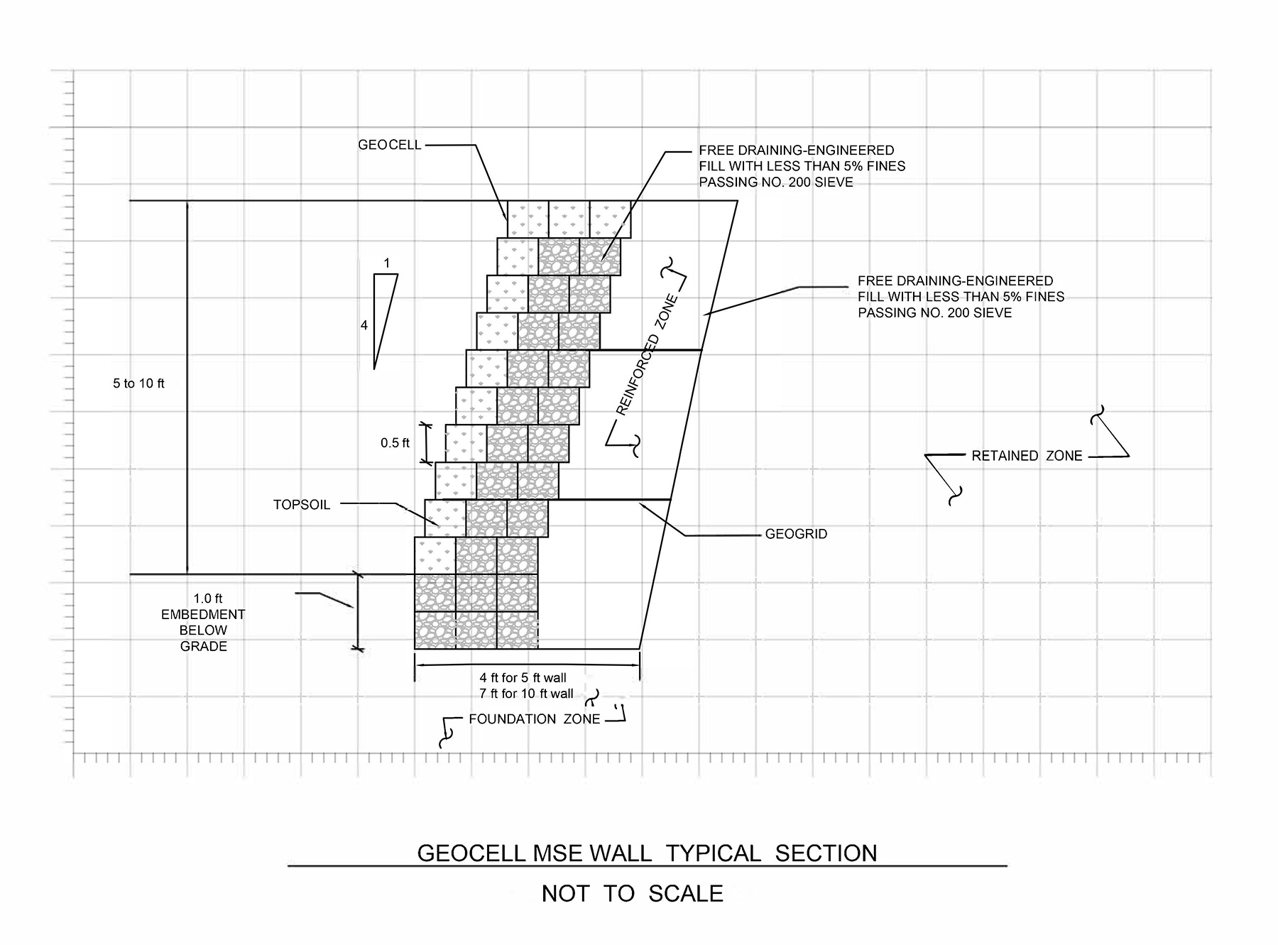
A retaining wall was constructed at the west boundary of the Mason yard, separating the site from the wetlands and the right of way for the Georgia Power transmission line. The weak and highly variable soils along the retaining wall required the use of a geocell mechanically stabilized earth wall with concrete footings and rigid panels. The geocells were supported on a layer of stone bedding over a stable subgrade; the stone bedding and geocell wall featured enough flexibility to tolerate some ground movements and a limited amount of settlement.
Crossing connections
To connect the Mason yard to the Chatham yard, the project constructed two bridges conveying eight rail lines across the Pipemakers Canal on a nine-degree curve. The bridges measure 120 ft long and are supported on five bents. Because the banks of the canal were low-lying marshland with elevation as low as zero, as much as 10 ft of fill was required to construct the embankment beyond the end bents. The project also realigned the canal to improve the hydraulic conveyance.
Because a layer of very soft silts and clays at the bridge site posed the potential for settlement issues and slope instability, the bridges were supported on prestressed concrete piles. The piles measured 18 in. square and 50 ft long for the end bents, with a compression design load of 95 tons, and 20 in. square and 55 ft long for the intermediate bents, with a compression design load of 150 tons.
Various design options were considered for stabilizing the embankments beyond the bridge end bents. Excavating the soil and replacing it with structural fill was considered too costly, while preloading the site with wick drains was not considered reliable enough for heavy loads. Instead, ground improvements using rigid inclusions were selected — an approach that obviated the need for two additional bridge bents that would have cost $7 million.
The design featured concrete elements installed using a conventional auger-cast pile rig and procedures. The concrete elements were 14 in. in diameter and typically 45 ft long and embedded into the marl formation for a nominal resistance of 300 kips. The concrete elements included nonreinforced and reinforced piles. The nonreinforced elements were used for compression loads to control settlements, while the reinforced elements were used to resist shear force on the slope and seismic loads.
The load transfer platform was composed of geogrid-reinforced crushed aggregate and capped with structural fill under the rail ballast and sub-ballast. A thermal integrity profiling method was performed to evaluate the cross-sectional integrity of cast-in-place piles and drilled shafts.
Supply chain success
At press time, work to eliminate the six at-grade crossings that affected the residential neighborhoods around the Garden City Terminal remained to be completed. But the majority of the Mega Rail project’s new features opened for business in November 2021, immediately increasing intermodal capacity to and from the Port of Savannah by more than 30%, according to the Georgia Ports Authority.
“The massive new Mason Mega Rail yard is coming online at the perfect time to help address the influx of cargo crossing the docks at the Port of Savannah,” announced Georgia Gov. Brian Kemp in a Nov. 12, 2021, press release. “The added rail capacity, along with new container storage on and off terminal, are already serving as important tools to resolve the supply chain issues for Georgia and the nation.”
This article was adapted from the paper “Ground Improvements for Georgia Ports’ Mason Mega Rail Project,” presented at the Ports 2022 conference, sponsored by ASCE’s Ports and Harbors Committee of the Coasts, Oceans, Ports, and Rivers Institute and PIANC, the World Association for Waterborne Transport Infrastructure, held in Honolulu on Sept. 18-21, 2022.
Guoming Lin, Ph.D., P.E., G.E., D.GE, F.ASCE, is a vice president and senior geotechnical consultant at Terracon Consultants in Savannah, Georgia. Christopher Novack, P.E., is a senior director of engineering and facilities maintenance, and Oliver Himbert, P.E., is a capital projects manager and facilities engineer at the Georgia Ports Authority in Savannah. Brad Woodall, P.E., is a senior structural engineer; Daniel Peavy, P.E., M.ASCE, is a senior civil engineer and project manager; and Honor Hutton, P.E., is a business unit leader at Moffatt & Nichol in Savannah.
SIDEBAR
Maintaining Intermodal
By Daniel Peavy, P.E., M.ASCE
The Mason Mega Rail project, located in Georgia within the Port of Savannah’s Garden City Terminal, involved unique civil engineering and port planning challenges — especially because the project had to be constructed through what has become the fastest-growing shipping container terminal in the United States while maintaining existing terminal operations. In addition, the port facility had to accommodate simultaneous operations for two Class I railroads.
Owned by the Georgia Ports Authority, the Garden City Terminal is the largest single container terminal in the United States. Roughly five years ago, however, the rail was nearing capacity at its two intermodal yards — Mason, used by Norfolk Southern Railway, and Chatham, used by CSX Transportation.
Separated by a waterway known as the Pipemakers Canal, the two yards were combined into a single facility through the Mason Mega Rail project, making it the largest on-dock rail facility in the United States.
By improving intermodal rail operations, the port planned to double its rail capacity to more than 1 million annual lifts, enabling the two railroads to each assemble 10,000 ft long unit trains — initially two such trains per railroad per day, eventually increasing to three per railroad each day.
The redevelopment and modernization project installed 20 mi of rail; constructed two nine-track rail bundles; installed 10 rail-mounted gantry cranes, spanning nine tracks with five cranes per bundle; and moved switching operations onto the terminal to accommodate six trains up to 10,000 ft in length. Understanding terminal operations, phasing construction, involving stakeholders, and communicating effectively were all key elements for a successful project implementation.
Working while working
A key challenge was that construction of the facility had to be performed while existing rail operations continued at the terminal. A detailed construction phasing plan was developed around maintaining rail operations, and it had to be implemented to gain incremental capacity without impacting existing throughput.
The Mega Rail project was initiated through authorizing a series of smaller projects while design was ongoing and while final stakeholder acceptance was achieved. Allowing construction on critical path items (such as geotechnical improvements and mass earthworks) to commence prior to having final design for the rail yard meant the project schedule could be advanced while planning and engineering continued.
The first construction package of the project was the purchase of the rail-mounted gantry cranes. Having the final general arrangement drawings of the cranes was critical to verifying the rail yard design and crane infrastructure.
Because there were two track bundles, construction could begin in one of the bundles while existing rail operations continued on the existing tracks where the other bundle would eventually be built.
To complete construction of the west bundle, a significant portion of the existing tracks in the Mason rail yard had to be demolished so that the track-side buffer could be paved and the pile-supported crane beams constructed. During the planning phase, the design team determined that the loss of existing track should be taken into account and existing rail operations made whole by building out portions of track in both bundles. Building out the tracks replaced the lost capacity and allowed the continued use of top-picks within the facility.
Once the west bundle was completed, Norfolk Southern rail operations moved onto the bundle and the east bundle was constructed. Upon completion of the east bundle, CSX moved its operations from the Chatham yard onto the east bundle, allowing reconfiguration of the Chatham yard to commence.
For the rail bundles to be operational, the new gantry cranes needed to be delivered, erected, and commissioned over the new rail yard. Waiting for a completed rail yard would have resulted in costly delays to the construction schedule and to the needed capacity improvements. To avoid these delays, temporary erection zones were created within the track bundles so that these activities could take place while construction continued.
By overlapping the crane schedule with the construction schedule, construction delays were avoided as work was performed concurrently. Orchestrating the rail capacities to keep pace with expected volumes while including the delivery, erection, and commissioning of the new gantry cranes within the same construction footprint required ample coordination with the engineer, site contractor, crane contractor, and the client, the Georgia Ports Authority.
Listening to stakeholders
A critical part of the project involved the various stakeholders who would be impacted by the construction of the facility; they were presented the plan, and their consent was sought. Stakeholder objectives were not aligned. Meeting the port’s capacity expectations, supplying two competing Class I railroads with operational benefits, and offering relief to the surrounding community created multiple criteria that had to be considered.
Effective communication with the stakeholders, prioritizing and highlighting the criteria that impacted them, and flexibility with the project master plan when addressing stakeholder comments allowed each stakeholder to be heard and created a united front for advancing the project.
The railroads desired greater separation between their operations. Neither railroad wanted an adverse event at the competing operation (such as a derailment) to keep both of them from operating. Addressing this comment led to creating a rail corridor (referred to as the “throat”) that consisted of three dedicated tracks for each railroad, six tracks total, that would act as an arrival track, a departure track, and a runaround track.
Accommodating the request had a significant cost impact on the project, but it allowed the port greater durability within its rail operations because it enabled the railroads to operate simultaneously and independently of each other.
The community had concerns about the increase in rail traffic as it related to life and safety vehicles and noise, going so far as to submit a plan to create a quiet zone in the neighborhood. A solution that addressed both concerns was to relocate Norfolk Southern’s mainline, called the foundation lead, along the throat and out of the neighboring community. Six at-grade crossings were removed, which eliminates the need for a quiet zone and enables life and safety vehicles to travel the neighborhood unimpeded by rail traffic.
While these are only two examples of the issues addressed, effectively communicating the benefits through stakeholder coordination meetings, operations workshops, and a public information open house were critical to achieving stakeholder concurrence. Early stakeholder involvement paved the way for smoother design and construction processes.
The Mason Mega Rail project extends the effective reach of the Port of Savannah’s Garden City Terminal to better serve existing destinations and expand into new destinations across inland U.S. markets. As container volumes continue to surge in Savannah, the fourth-busiest port in the United States, having the capability of directing nearly 25% of terminal freight via rail reduces the number of trucks on the road, reduces traffic congestion and emissions, and permits a greater speed to market — all of which has an economic impact throughout the state of Georgia and the destinations the port serves.
As this project demonstrated, reconfiguring existing facilities and eliminating conflicts through the local community can generate support from environmental and community stakeholders. But these efforts also have the potential to create capacity and operational strains that can plague a project’s execution. By engaging in meaningful stakeholder involvement, effectively communicating the desired planning objectives, and executing robust construction phasing plans, operational strains can be mitigated and a successful project implementation can be achieved.
This sidebar was adapted from the paper “Georgia Ports Authority’s Mega Rail Project: Increasing Intermodal Capacity, While Maintaining Intermodal Operations,” presented at the Ports 2022 conference, sponsored by ASCE’s Ports and Harbors Committee of the Coasts, Oceans, Ports, and Rivers Institute, and PIANC, the World Association for Waterborne Transport Infrastructure, held in Honolulu Sept. 18-21, 2022.
Daniel Peavy, P.E., M.ASCE, is a senior civil engineer and project manager at Moffatt & Nichol, in Savannah, Georgia.
Project credits
Client: Georgia Ports Authority
Geotechnical engineering, environmental and construction testing: Terracon Consultants, Savannah, Georgia
Project management, conceptual planning, civil engineering design, construction management, and grant support: Moffatt & Nichol, Savannah
Prime site contractor: Astra Group LLC, Woodstock, Georgia
Dynamic compaction contractor: TerraSystems Inc., Lovettsville, Virginia, and Densification Inc., Paeonian Springs, Virginia
Bridge contractor: Continental Heavy Civil Corp., Brunswick, Georgia
Rail contractor: G.W. Peoples, Arlington, Virginia
Crane beam pile driving contractor: Goettle, Cincinnati
Bridge site ground improvement: Berkel, Austell, Georgia; rigid inclusion design: Dan Brown & Associates PC, Sequatchie, Tennessee
Piling contractors: Goettle for the rail-mounted gantry runways and Continental Heavy Civil for the rail bridge foundations
This article and sidebar first appeared in the March/April 2023 issue of Civil Engineering as “Making ‘Mega’ Ground Improvements” and “Maintaining Intermodal.”