By Nasser Al-Nuaimi, Ph.D., and Hilal Al-Kuwari
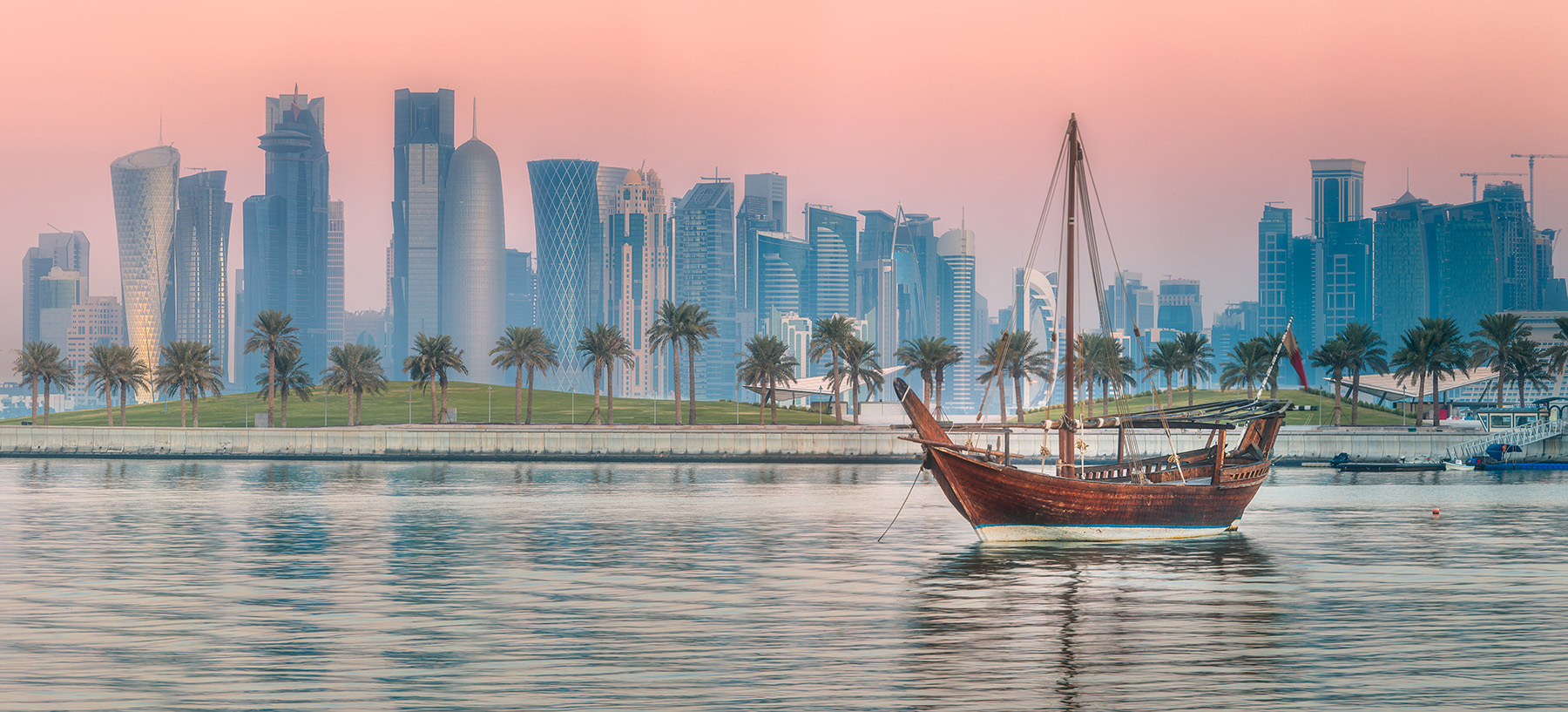
The 2022 World Cup, held in Qatar, was the first international soccer tournament to take place in an Arab country. Consequently, the design of multiple stadiums followed a Middle Eastern aesthetic that also accommodated plans for how the facilities could be used after the games.
The eight soccer stadiums that hosted the 2022 World Cup in Qatar are inspiring feats of civil engineering. With one designed like a traditional Middle Eastern hat, another shaped as a Bedouin tent, and one made of nearly a thousand shipping containers, the stadiums were certainly one of the highlights of the quadrennial tournament.
Qatar is a peninsular Arab nation with a population of around 2.65 million. Because summer temperatures in Qatar can reach more than 50 C (with surfaces exposed to direct sunlight reaching temperatures above 85 C), this was the first World Cup in the northern hemisphere held in the late fall — beginning Nov. 20 and ending Dec. 18. The Qatari government established the Supreme Committee for Delivery and Legacy to deliver and manage the eight stadiums as well as the overall tournament.
Although previous World Cup tournaments took place across multiple host cities that might be hundreds, or even thousands, of kilometers apart, all 64 matches were held in one compact area for the first time in history. All eight stadiums are within a roughly 34 km radius in central Doha, Qatar’s capital, and the venues are linked by the country’s existing metro system or can be reached by roughly an hour’s drive. This proximity meant fans could stay in one accommodation for the entire tournament and even attend two matches on the same day at different venues.
All eight stadiums were powered by a solar panel farm and were equipped with extensive cooling systems, including outdoor air conditioning in some. Seven of the eight stadiums — Al Janoub, Lusail, Al Bayt, Al Thumama, Ahmad Bin Ali, Education City, and Stadium 974 — were built from scratch to host the World Cup tournament. The eighth facility, Khalifa International Stadium, dating to 1976, underwent extensive redevelopment. Six of the stadiums were designed to have roughly half their seating capacity removed after the tournament so they could be reconfigured for the local community, and Stadium 974, which was made from shipping containers, will be dismantled.
The preliminary work to dismantle Stadium 974 was underway at press time, but the downsizing of other stadiums will not begin until at least next year, as those facilities are hosting games for the Asian Football Confederation’s upcoming Asian Cup, which will feature matches in Qatar in January and February.
This article focuses on the unique design, engineering, and construction aspects of two of the Qatar World Cup stadiums — Al Janoub and Lusail — while the other six venues will be featured in Civil Engineering Online.
Sailing into sport
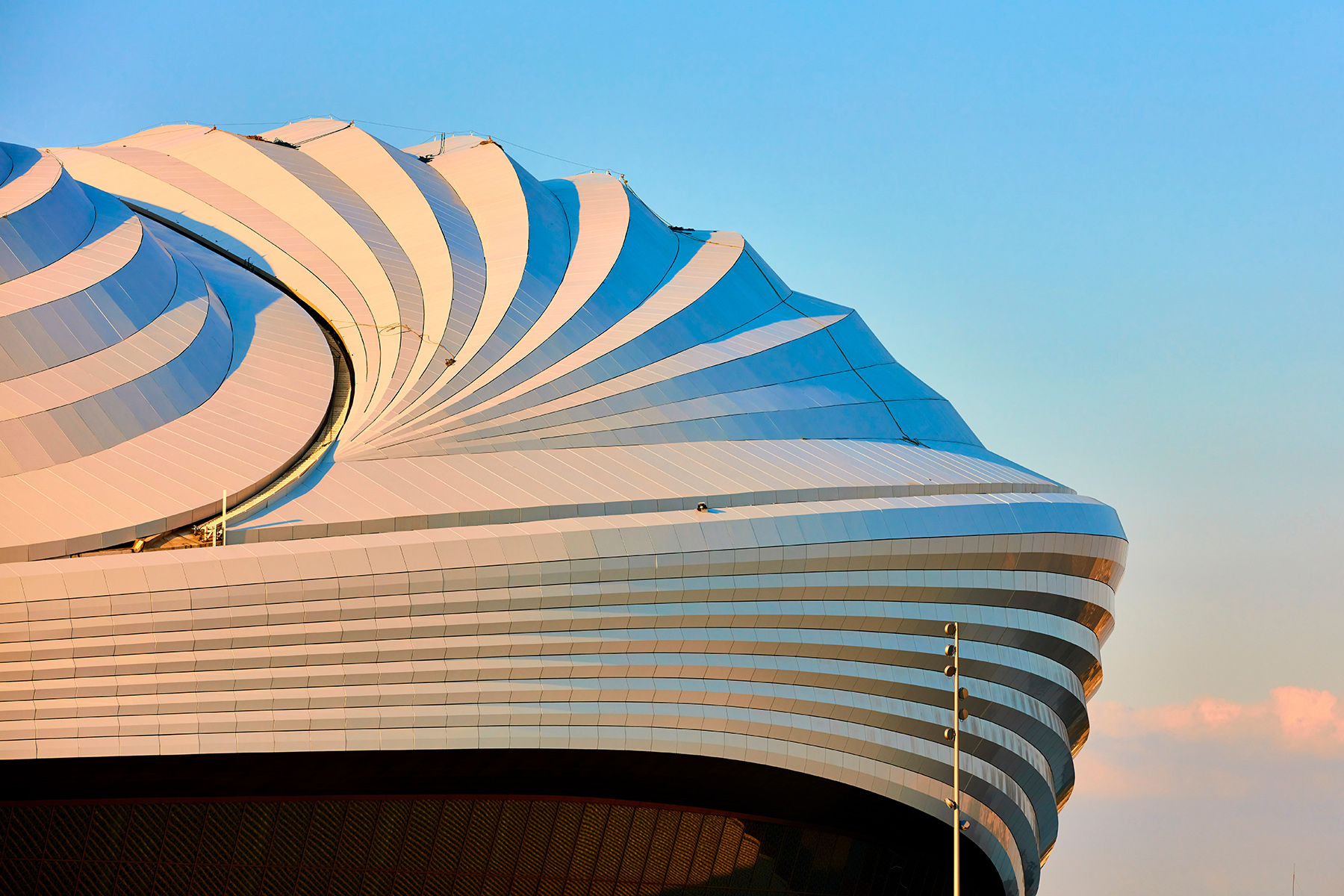
Al Janoub Stadium in Al Wakrah, one of Qatar’s oldest inhabited areas, was the first to be designed. Intended as the centerpiece of a new public sports precinct to the south of Doha, Al Janoub’s form was inspired by the waterfront region’s rich seafaring heritage, visible in the colors, patterns, and materials found throughout the stadium. That heritage was especially evident in the stadium’s overall abstract expression of the dhow, an Arabian pearl fishing boat of great cultural significance in Qatar and a common sight in Al Wakrah’s port.
The stadium’s roof was inspired by the hulls of several dhows turned upside down and clustered together. In particular, the roof’s arrangement of beams reflects the interior structure of a dhow’s hull. The stadium’s facades slant outward and taper in elevation, reminiscent of the pleating of a dhow’s sails. The dhow theme is emphasized through the large overhang of the stadium’s eaves that incorporated strips of metal cladding reminiscent of the timber structures used in a dhow.
A complex interaction of factors defined the roof, including its architectural form, insulation, pitch conditioning, acoustic atmosphere, and sound quality. Other key factors were the cooling systems, ventilation, lighting, speakers, gantries, audio-visual and communications technology, camera and broadcasting platforms, rigging systems, drainage, and fire protection.
The structure is supported primarily on a combination of raft and pad foundations resting on limestone rock underneath. The highest-loaded primary roof supports rest on piles to resist the highest combination of axial loads, uplift, and overturning effects.
Planning for the future
The form of Al Janoub’s seating bowl was generated with 3D parabolic geometry using Autodesk Revit 3D, manufactured by San Francisco-based Autodesk, and Rhinoceros 3D and Grasshopper, both manufactured by Robert McNeel & Associates of Seattle. The design ensured excellent sightlines from every angle, while the space behind the seats accommodates technical, welfare, hospitality, media, broadcast, and commercial areas.
During the World Cup, Al Janoub Stadium held up to 40,000 spectators; the stadium was designed so it can be converted to a 20,000-person capacity facility to serve the Al Wakrah football club and local community requirements. To maintain the overall architectural form for both modes, the stadium bowl features a permanent cast-in-place, reinforced-concrete lower tier frame that supports precast concrete terracing and a temporary demountable upper tier constructed in steelwork.
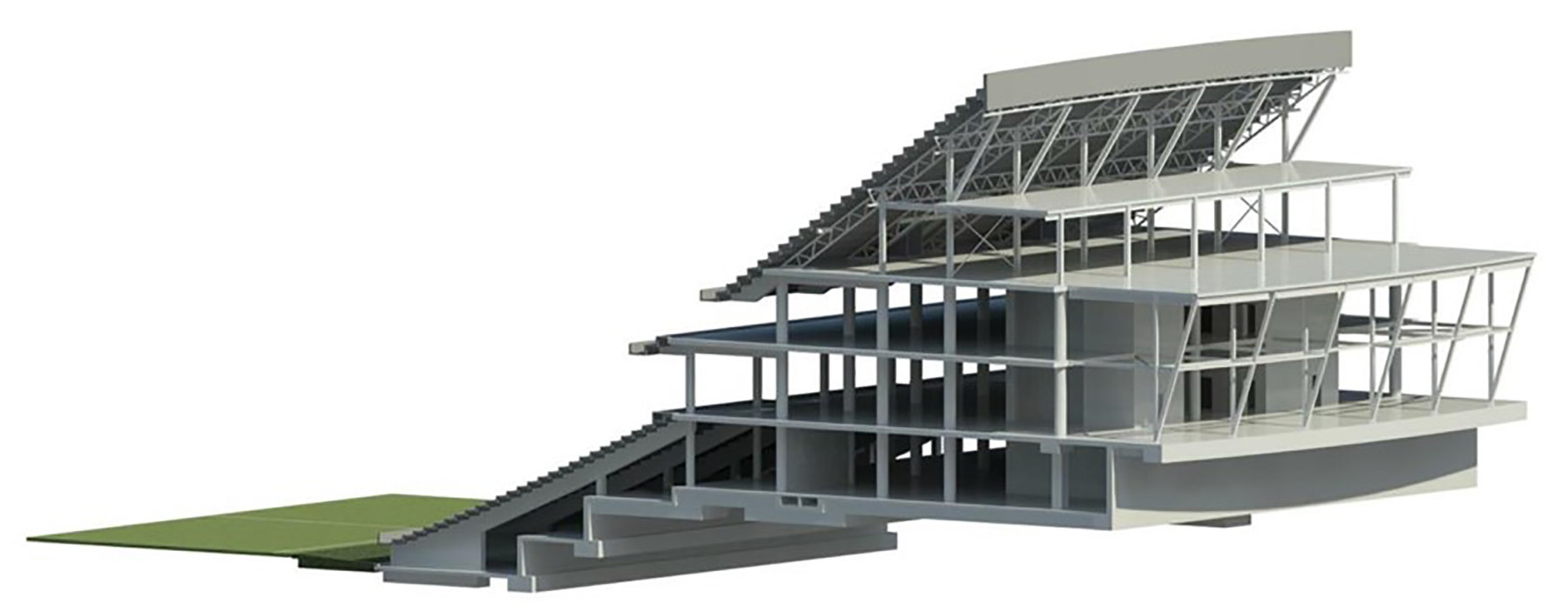
Al Janoub Stadium’s steel roof system includes a fixed outer structure, featuring an arrangement of long-span arches, and an operable inner structure. When the operable inner structure is closed over the pitch, the stands and the pitch are shaded and protected from the weather. In its downsized mode, the closed roof transforms the venue from an open-air stadium into a fully enclosed multipurpose arena.
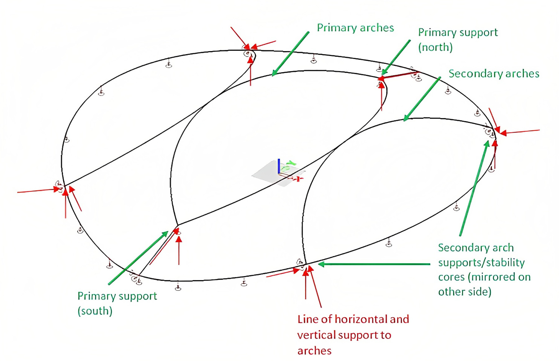
To control stiffness distribution, the project team designed the roof to be independent of the reinforced-concrete bowl structure. The primary arches, formed as 3D trusses, span the length of the approximately 230 m building. The arches are supported on large, sculptural fabricated-steel buttresses on the north and south sides of the stadium. Secondary arches are supported on raking concrete towers.
The experience of soccer fans during the games at Al Janoub Stadium was overwhelmingly positive. From the initial design phase to the finished product, Al Janoub Stadium stands as an exceptional civil engineering showcase of seamlessly blending functionality and elegance.
Designing for light
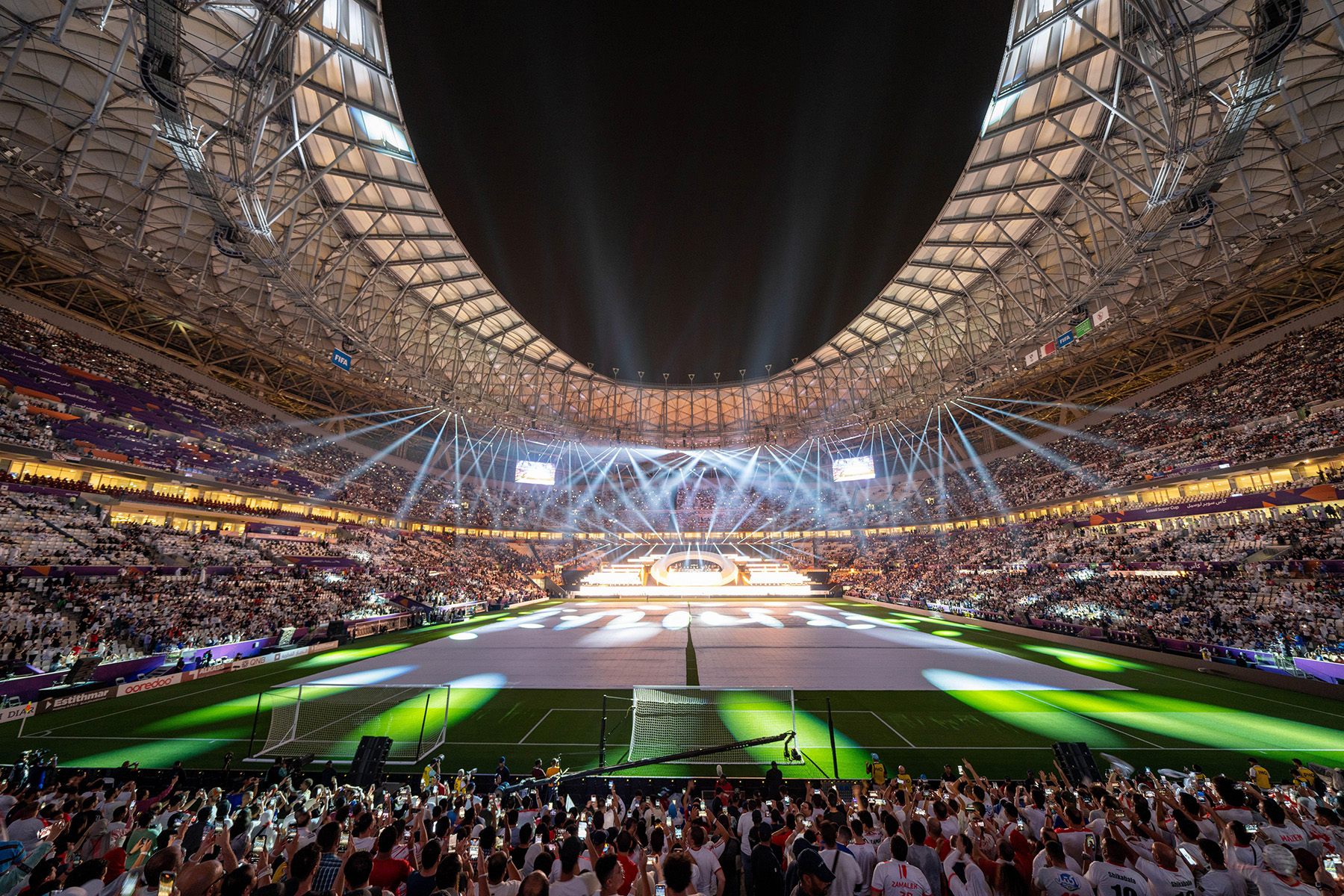
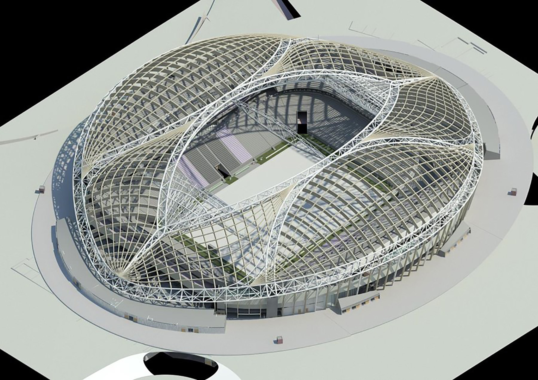
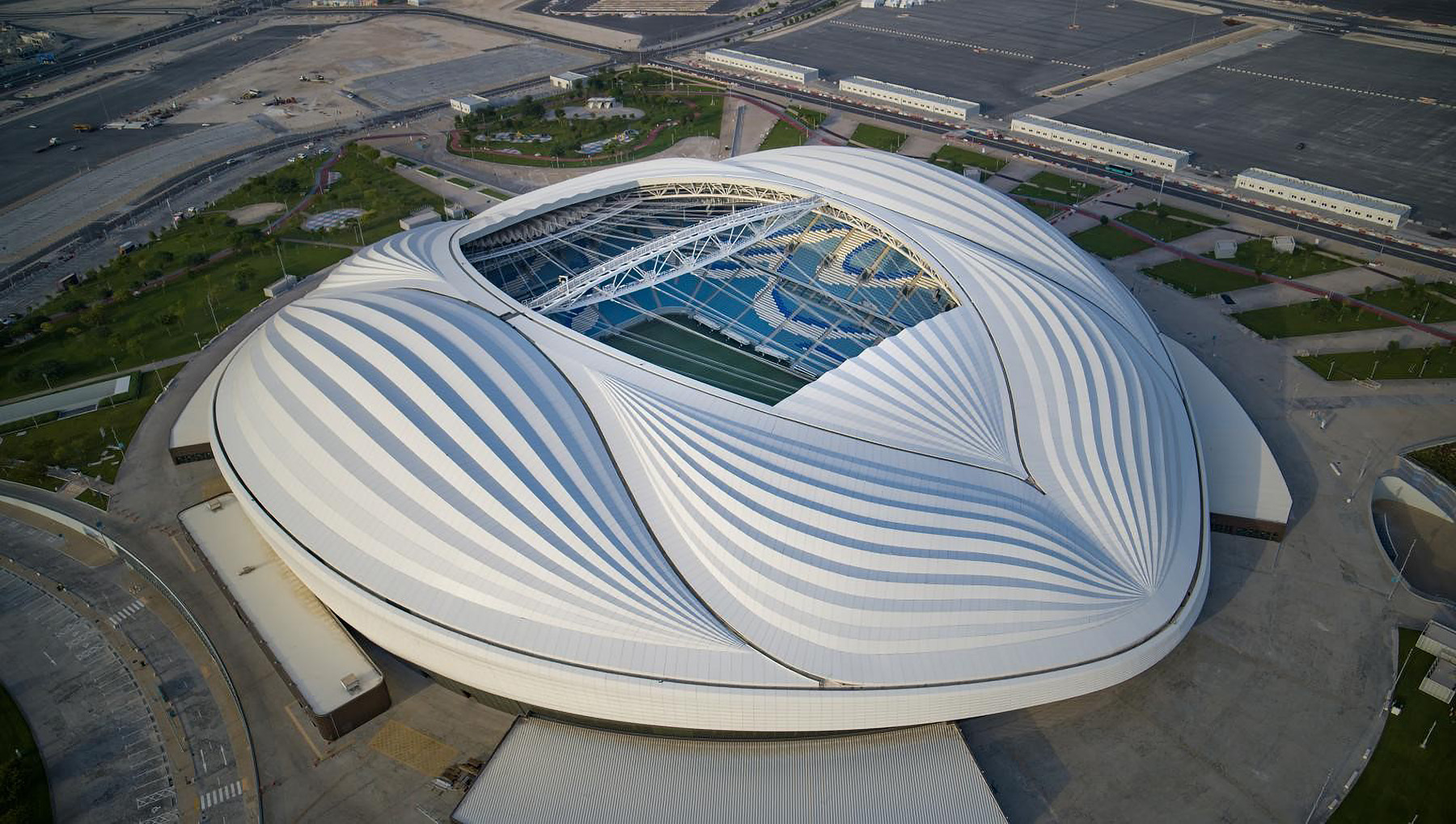
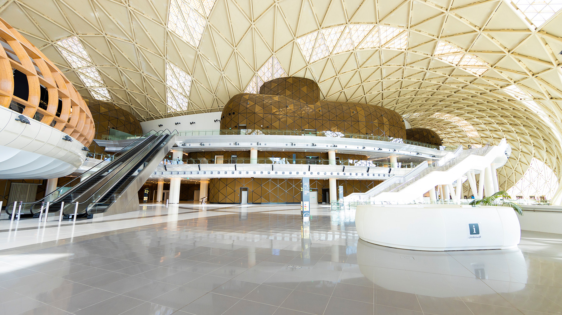
The layout of the 80,000-seat Lusail Stadium, the venue that hosted the final game of the 2022 World Cup, was inspired by the interplay of light and shadow that characterizes the fanar, an Arabic lantern, as well as the intricate decorative motifs found on household items across the Arab world. Lusail Stadium is a true engineering feat, as demonstrated by its bowl structure, facade (called the vessel structure), and roof.
The key structural elements of Lusail Stadium include:
- A reinforced-concrete bowl structure, including its shear walls, columns, beams, and slabs. The bowl has 6-8 levels (depending on the zone) and supports seating tiers; utilities; and the mechanical, electrical, and plumbing systems.
- A steel-framed flooring system with composite concrete deck slabs for a cantilevered (outward) extension of the bowl from level 5 and above. The outward floor extensions are supported by a truss system that spans between 24 concrete plinths, spaced equally on circumferential grids around the bowl; the plinths also support the roof structure.
- Precast concrete elements for the tiers, rakers, and bleachers, most of which can be removed to create a smaller facility.
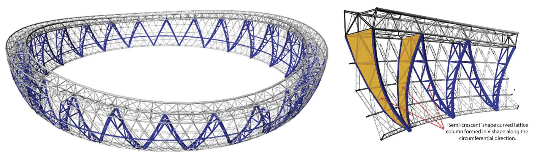
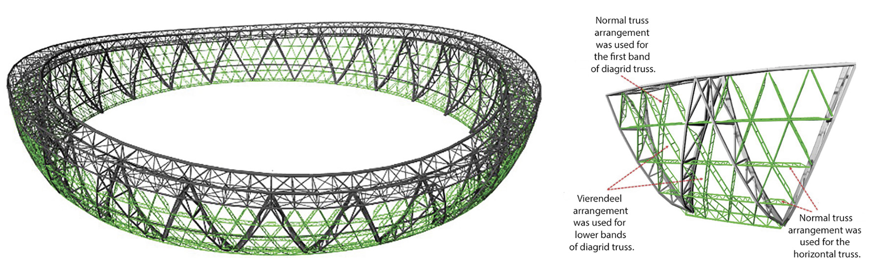
- The structural steel system for the compression ring, V-shaped frames, and vessel facade support structure.
- A steel cable net structure with tension and compression rings as the roof structure, supported by curved V-shaped steel perimeter frames and the steel vessel frame structure.
- Foundations that include isolated pad footings to support the columns and a raft foundation for the core walls and the perimeter cantilever concrete plinths.
Making models
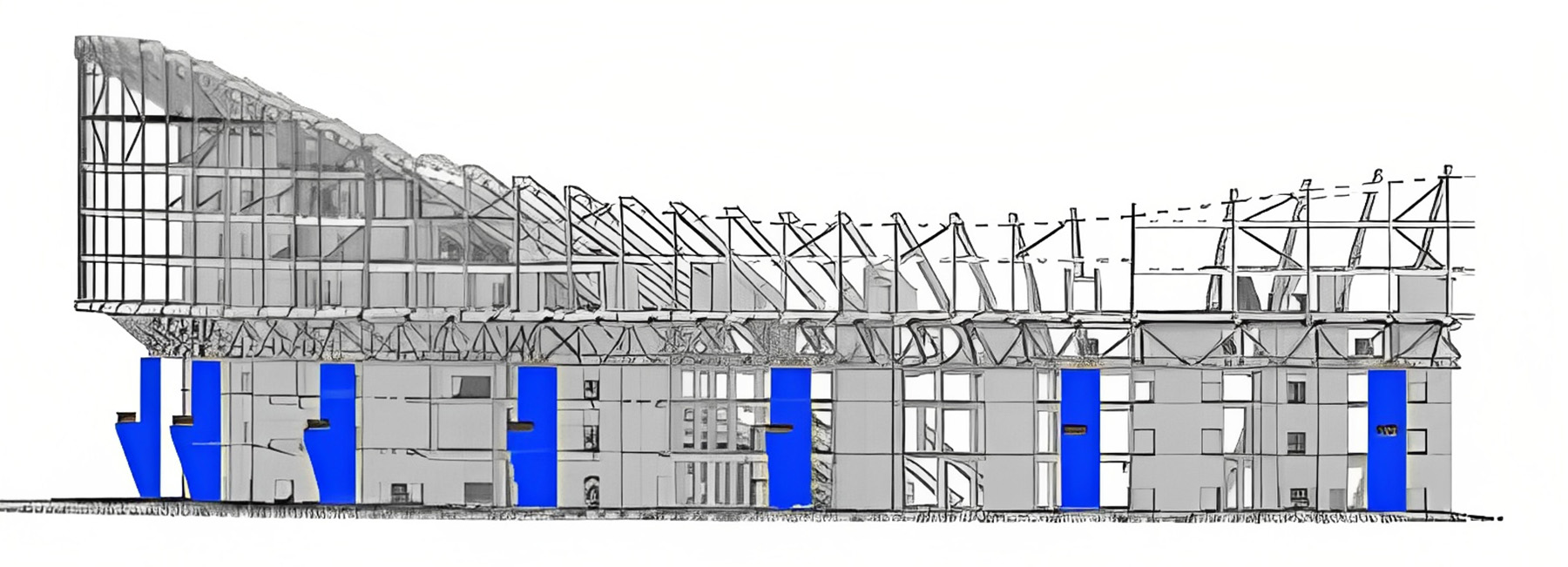
Expansion joints were introduced at eight strategically selected locations without compromising the architectural design. These joints help accommodate the strains induced in the slabs and take into account the effect of the rigid core walls and the curved shape of the slabs in plan. Analytical 3D finite element ETABS models — from Computers and Structures Inc. of Walnut Creek, California — were created for various zones within the full-sized tournament stadium as well as for the downsized post-tournament facility. Reinforced-concrete beams, columns, and core walls were designed using ETABS.
The SAFE software system, also from Computers and Structures, was used to develop the structure’s suspended reinforced-concrete slabs, designated as suspended because they are not in direct contact with the ground. Three SAFE models were created for serviceability, strength, and thermal conditions for the full-scale and downsized Lusail designs. In particular, the project teams used the thermal model to account for the long-term shrinkage and temperature variations and evaluate long-term deflections and crack widths while also taking into account the rigid core walls and the curved slab shape in plan.
Supporting the roof
The primary function of the steel vessel structure is to support the roof structure and form the main skeleton on the vertical elevation that supports the facade panels. The vessel structure sits outside the concrete seating bowl on the 24 concrete plinths, separated by bearings from the concrete bowl structure below. The roof and the vessel structure are independent structurally from the concrete/steel bowl structure.
From a design point of view, the vessel structure forms a series of triangular-shaped lattices on the stadium elevation and at the same time ensures adequate stiffness and strength envelop the stadium. The steel structure consists of the compression ring (the geometry is governed by the saddle-shaped roof and the cable net grid on the facade), the curved V frames, and the vessel structure.
Working in tension
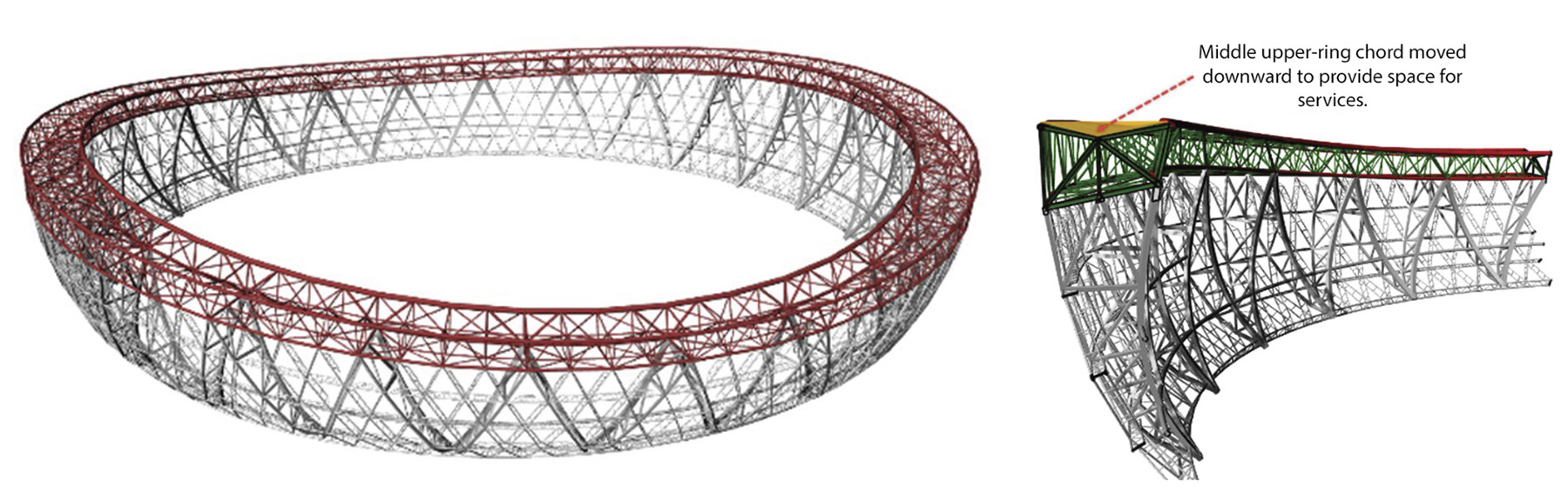
The stadium’s spoke-wheel-type cable net roof system, comprising two inner tension rings and one outer compression ring truss connected by radial spokes, is the most lightweight and thus structurally efficient and economical system for large-span roofs.
The tensioned radial cables span between the perimeter compression truss and an interior tension ring (featuring upper and lower tension rings) that form the central oculus of the roof. The upper and lower cable layers are separated by spacer strut elements that create the internal geometry of the roof. Steel bracing cables provide additional stiffness in plan and elevation to accommodate local variations in loading. The overall form of the roof structure is a hyperbolic paraboloid, the geometry of which was derived mathematically to create the most efficient and geometrically “pure” cable structure form.
The system was designed so that vertical loads would cause the prestressed radial cables to deflect through an angle and generate an equal and opposite reaction force. In this way the roof responds dynamically to the applied loading so that the applied load, cable geometry, and internal prestress forces reach an equilibrium condition.
Downward loading is accommodated by internal strut elements on the roof’s polytetrafluoroethylene membrane surface. Loads are transferred into the lower cable net, which hangs as a catenary between the perimeter compression ring and the lower tension ring. An upper layer of cables accommodates uplift loading in a similar way.
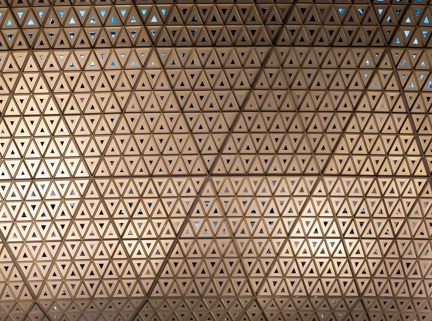
The PTFE membrane cladding system provides shading and protection against the weather. This cladding system is supported and formed by the roof’s secondary arches and the bracing cables that act as the skeleton of the membrane, creating a diamond pattern on the membrane’s surface.
Controlling for accuracy
Achieving the geometric accuracy required for the Lusail roof was quite challenging, given the fast-paced construction schedule, which did not give the project team sufficient time to fabricate the membrane and facade based on the as-built geometries and then adapt to any deviations.
For the construction phase, the project team relied on building information modeling software midas Gen, manufactured by Midas IT Co. Ltd of Seongnam-si, South Korea. This simulation software divided the process of constructing the steel and roof structures into eight stages: V frame installation, compression ring installation, vessel truss V segment (partial) installation, V frame temporary support tower depropping, vessel truss segments installation, primary cable system installation, secondary cable system and arches installation, and roof membrane installation.
The simulation and analyses results of the installation stages determined the on-site construction sequence, a process that was quite detailed. For example, seven points on the outer chord of the V frame and compression ring were chosen to monitor the geometric deviations across all eight stages listed above. During the V frame installation, 48 pieces of V-shaped frames were installed on the spherical bearings and supported by temporary towers. According to the simulation, the biggest deformation for a single V frame installation was 74 mm at the middle of the V frame; pre-camber was thus introduced during the V frame assembly to absorb the deviation during this initial construction stage. The value of pre-camber was based on the deformation value calculated through the simulation, and the simulated coordinates of installing each single V frame were then used as the target during construction.
During the stage 2 compression ring installation process, the project team divided the compression ring into 24 segments. Because the perimeter length of the compression ring was approximately 1 km, temperature effects were significant and had to be considered. Based on the simulation analysis, four closure segments were introduced in four corner zones. Just as in stage 1, the simulated coordinates of installing each compression ring were used as the target because the geometry of individual compression ring segments was impacted by the subsequent segments. The pinholes of the compression ring’s cable connection plates served as the geometry control points.
By following this staged process (relying on the analysis) and designing mechanisms to accommodate the deviations at key locations, the project team was able to control the geometrical accuracy. At any given stage, the design team designed the mechanisms to adapt and absorb any deviations from the previous stage; this was made possible by a series of adjustable connections that could absorb the deviations and hence avoid their accumulation.
The project team continually monitored the movements of the structural members during each construction stage and compared them with the appropriate simulations. A maximum difference of 7 mm was noted throughout the construction phase, which was not considered significant.
Lusail Stadium was designed so it could be adapted to provide the local community with multiple uses, including schools, residential apartments, medical clinics, retail, parking, and other amenities.
The 2022 World Cup marked the first time the world’s largest sporting event was held in the Middle East. But in many ways, the games were more than just a major international sporting event. The diverse and ambitious nature of the eight soccer stadiums, combined with the details and constraints of construction in the region, provided an opportunity for civil engineers worldwide to share knowledge and enhance best practices.
And that was a goal as important as any scored on the fields.
Nasser Al-Nuaimi, Ph.D., is the associate vice president for research and graduate studies at Qatar University and formerly served as the director of the university’s Center for Advanced Materials. Hilal Al-Kuwari was the technical director of for the 2022 World Cup stadiums at Qatar’s Supreme Committee for Delivery and Legacy. He died in July 2022 shortly after completing his portion of this article.
Project credits
Al Janoub Stadium
Client: Supreme Committee for Delivery and Legacy, Al Wakrah, Qatar
Project management consultant: KEO International Consultants, Doha, Qatar
Concept design architects: Zaha Hadid Architects, London, and AECOM, Dallas
Concept sports architect; design structural engineer; design mechanical, electrical, and plumbing engineer; and construction supervision consultant: AECOM
Architect of record: Qatar Design Consortium, Doha
Design-build contractor: Doha-based joint venture of Midmac Contracting Co., Six Construct Qatar, and PORR Qatar Construction
Executive architect, executive sports architect, and executive interior designer: SCAU architecture, Paris and Doha offices
Executive structural engineer: Maffeis Engineering SpA, Solagna, Italy
Executive MEP engineer: Jain, Toronto; Dubai, United Arab Emirates; New Delhi; and Doha offices
Lusail Stadium
Client: Supreme Committee for Delivery and Legacy, Al Wakrah
Project management consultant: TiME Qatar, Doha
Concept design architect and master planner: Foster + Partners, London
Concept sports architect: POPULOUS, London
Concept structural and MEP engineer: Arup, London and Doha
Design-build contractors: HBK Contracting Co. WLL, Doha, and China Railway Construction Corp. Ltd., Beijing
Construction supervision consultant: WSP, Montreal
Executive architect: KEO International Consultants and Aurecon Group Pty. Ltd., Docklands, Australia
Executive sports architects and executive interior design: AFL Architects, Manchester, England
Executive structural engineer: Aurecon Group Pty. Ltd. (bowl) and Beijing Institute of Architectural Design, Beijing (roof and vessel)
Executive MEP engineer: Aurecon Group Pty. Ltd. and HBK Engineering, Doha
Architect and engineer of record: Diwan Al Emara Architects, Engineers & Planners, Doha
This article first appeared in the November/December 2023 print issue of Civil Engineering as “World Class.”