By Kevin C. Poulin, Ph.D., P.E., M.ASCE, Lauren P. Feinstein, P.E., David A. Ribbans, P.E., M.ASCE, and Filippo Masetti, P.E., M.ASCE
At The Frick Collection in New York City, preserving historically protected architectural elements while accomplishing a renovation and expansion required a multitude of strategies.
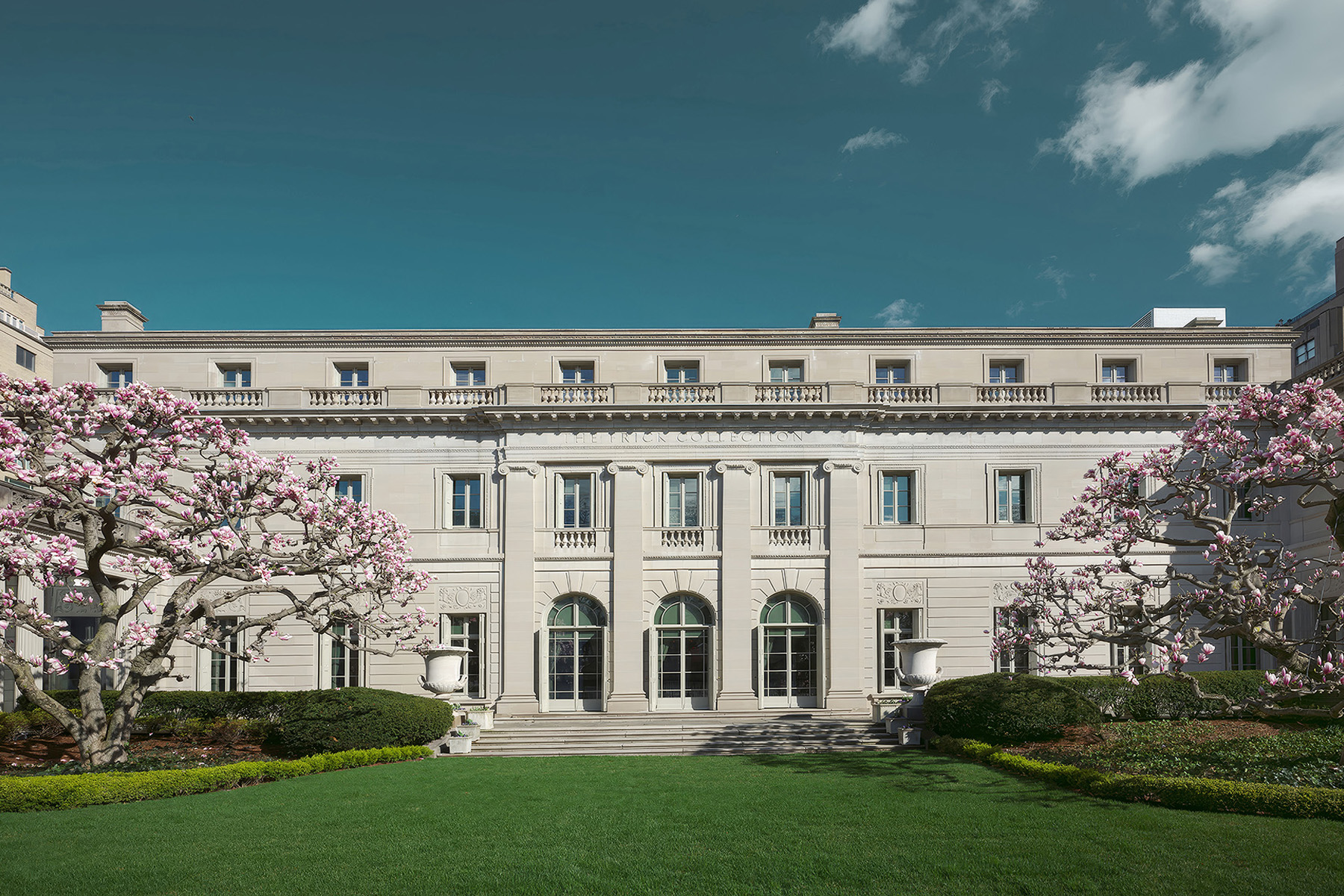
The Frick Collection, once just a large family home, is a beloved New York City institution, an important cultural resource, and a designated landmark by the New York City Landmarks Preservation Commission and the National Register of Historic Places. The architectural firm Carrère and Hastings designed the original mansion for industrialist and art collector Henry Clay Frick. The Gilded Age residence, completed in 1914, housed his unparalleled collection of Old Masters and 19th-century paintings and was intended to become a public museum.
In 1935, years after the deaths of Henry and his wife, their daughter Helen Clay Frick led the conversion of the mansion into a museum, and the architect John Russell Pope designed an expansion that doubled the size of the overall structure’s footprint. It included new galleries, an interior garden known as the Garden Court, the Music Room (also the Lecture Hall), and a larger building to house the Frick Art Research Library, or FARL. During World War II, the museum built a three-story below-grade art storage vault that was designed to survive bomb blasts.
In the following decades, The Frick Collection purchased neighboring properties to provide an expanded, contiguous site. In 1977, the museum constructed the Reception Hall and the 70th Street Garden. Since its last major expansion, the museum’s collection of art and archival documents has continued to grow significantly, creating the need for more gallery space and a larger art conservation center.
By 2017, The Frick Collection had engaged Selldorf Architects and Beyer Blinder Belle Architects & Planners LLP to design an expansion and oversee the renovation of the museum’s historic buildings. Simpson Gumpertz and Heger Associates Inc., P.C., was the structural engineer of record, and the engineers collaborated with the consulting engineering firm Guy Nordenson and Associates, which assisted with the initial structural design through the design development phase. Sciame Construction was the general contractor.
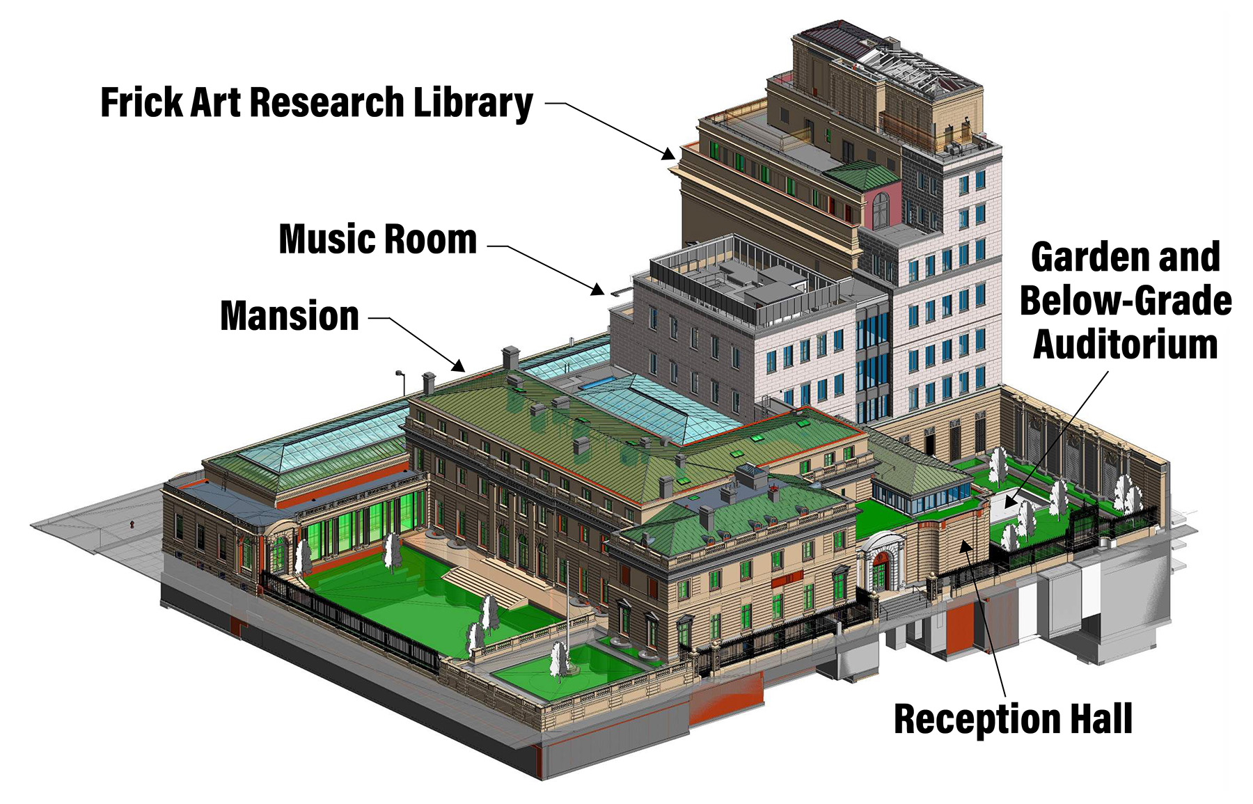
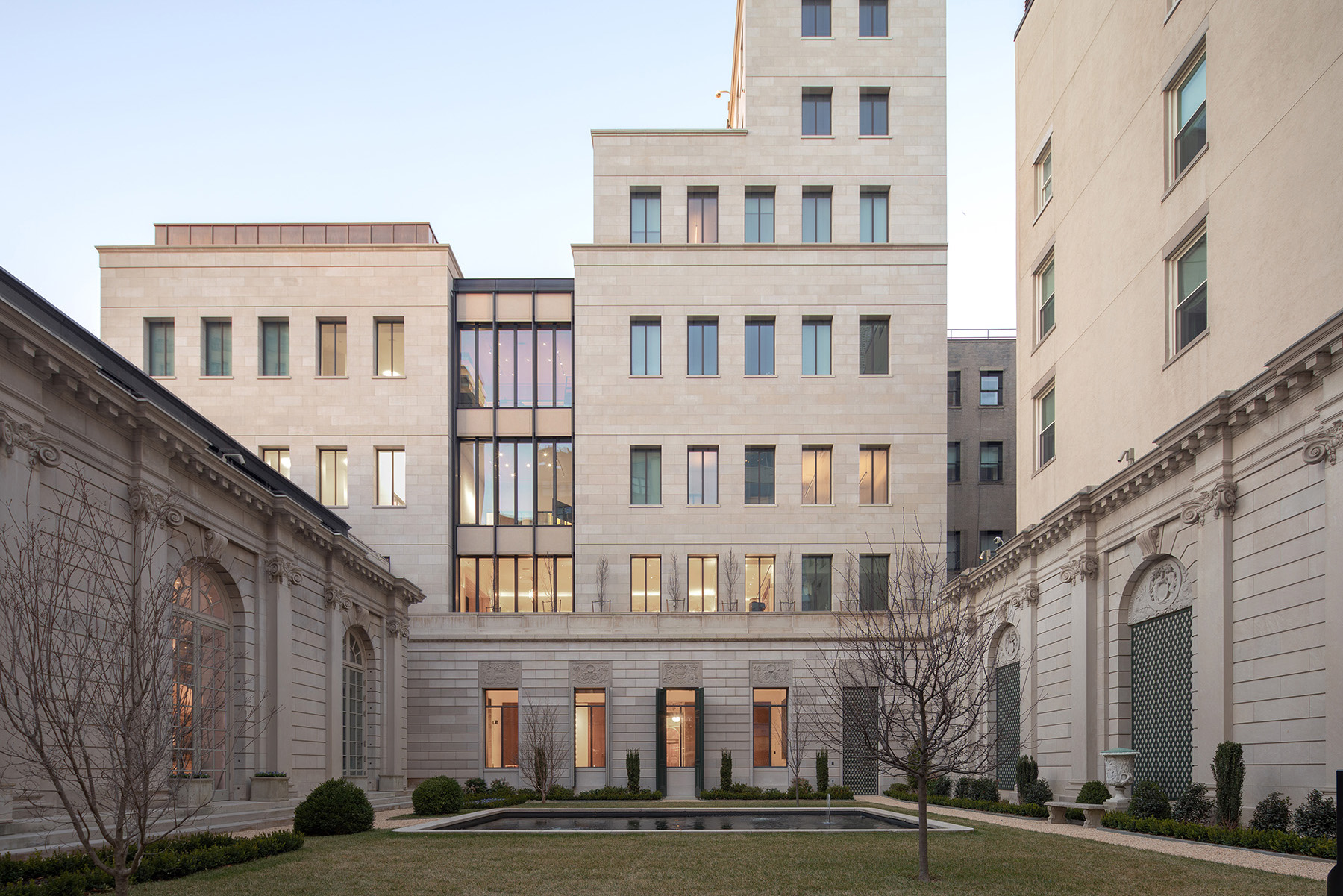
The expansion includes a three-story addition atop the existing structure, known as an overbuild, to house special exhibitions and a conservation studio, a partial overbuild above the Reception Hall, and a narrow nine-story addition to the FARL. The project team removed the art storage vault below the 70th Street Garden, added a below-grade auditorium in its stead, and then restored the historic garden.
The project also included restoration of the mansion — to provide unprecedented public access to the second floor — and replacement of skylights over the existing Garden Court and gallery spaces.
Additionally, new mechanical, electrical, and plumbing infrastructure was installed for increased energy efficiency, along with a new mechanical bulkhead for the FARL. New elevators, stairs, and amenities were added throughout the buildings.
During the eight-year project, SGH documented many aspects of the existing buildings for which original drawings did not exist, redirected load paths, strengthened and repaired the existing structure, removed and replaced lateral-load-resisting systems, integrated new construction with archaic structural systems, and addressed unforeseen field conditions.
Organized by building, this article presents the challenges SGH faced and the solutions its engineers developed to expand the museum’s capabilities, improve the visitor experience, and offer further access to the Frick’s admired collection.
Music Room: Three-story overbuild
The Music Room was part of the 1935 museum expansion, and the double-height circular room was the setting for lectures, educational programs, and concerts. Although audiences enjoyed close-up concert performances, the intimate room had limitations, including uneven acoustics. The architects relocated the performance space and, in its place, designed a centrally located special exhibitions gallery and the new Sherman Fairchild Center for Art Conservation.
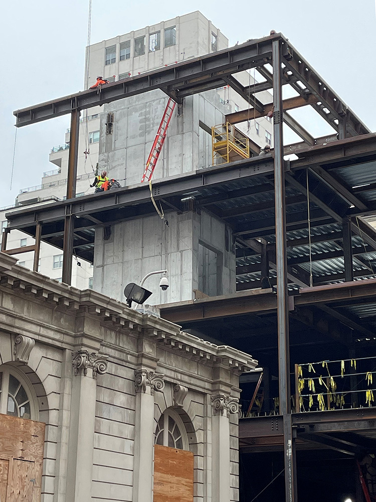
During the renovation, the contractor demolished the upper floors and roof but kept the perimeter steel columns, the first-floor structure, and the below-grade construction. A new three-story building was added on top of the first floor for a full height of four stories, and the footprint of the building was enlarged to the south.
To support the overbuild, the project team needed to strengthen the existing columns and enlarge their footings.
The team also needed to add a new lateral system, extend the existing columns, and cantilever the new third and fourth floors over the adjacent Garden Court. The perimeter columns were recessed into the masonry walls that separated the Music Room from the Garden Court to the west and from the mansion’s Oval Gallery to the north.
Because of the historic finishes in these adjacent spaces, the contractor could only remove masonry to strengthen columns from the former Music Room side, which resulted in asymmetric placement of steel reinforcement plates, mostly one-sided within the flanges, for the full height of the columns.
The SGH engineers enlarged the footings and column piers and designed stiffened extensions to the existing column baseplates. Between two strengthened columns on the north end of the building, diagonals were added to form a braced frame and to strengthen existing connections.
The contractor also added two concrete shear walls, an elevator core at the south end of the building, and another located along the east wall of the building.
The east shear wall starts as a liner wall inside the footprint of the existing foundation wall. It “steps over” the top of the existing wall (toward the east), above the existing first floor. Between the first and second floors, the shear wall doubles in thickness to provide a transition zone for gravity and lateral forces. The gravity eccentricity was resolved by transferring a force couple to the concrete diaphragms of the existing cellar and the new second floor.
Since the existing first-floor construction was not demolished, the contractor needed to repair the draped-mesh cinder-concrete floor slabs, which had varying degrees of concrete spalling and reinforcement corrosion. In some locations, the deterioration required the removal and replacement of entire slab bays with new concrete-on-metal deck slabs. In other locations, engineers designed a new topping slab to function as a structural slab and considered the existing cinder-concrete floor slab to function as permanent formwork. Smaller spalls were fixed using localized concrete repair details.
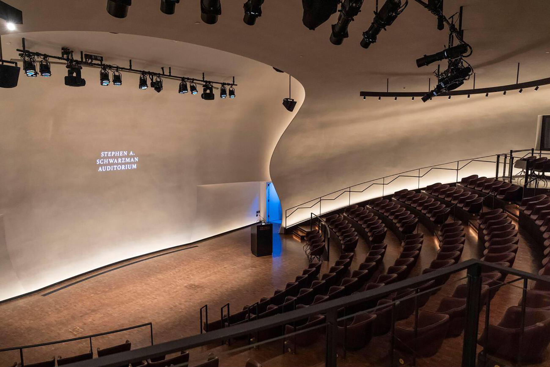
Stephen A. Schwarzman Auditorium
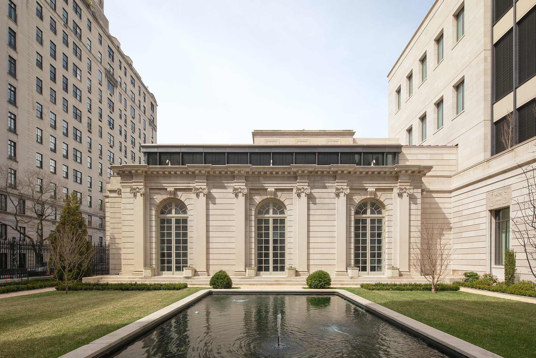
Because the original Music Room was converted to a gallery for special exhibitions, the architects designed a new 220-seat, below-grade auditorium for lectures, symposia, and musical performances. To achieve this, the contractor needed to remove the 70th Street Garden, excavate and partially demolish the art vault beneath the garden, build the new auditorium below grade, and then restore the garden.

The new performance space was to be more accommodating for audiences than the prior Music Room, and the state-of-the-art acoustics would improve the sound quality of all the programs.
Construction of the new space required several months of rock excavation adjacent to the existing art vault to remove approximately 20 ft of bedrock. The second below-grade slab of the vault became the support for the auditorium stage.
The art vault was built in 1940 and, as mentioned previously, was designed to resist bomb blasts. The original construction of the vault consisted of two 18 in. thick reinforced-concrete walls separated by an 18 in. thick sand layer. A portion of the double walls above the stage slab was reinforced with Steelcrete, dense sheets of expanded metal mesh combined with conventional reinforcing bars. The design intent for the new auditorium was to demolish the west double walls and the upper slabs while keeping the east double walls. These walls were to span from the stage slab to the new slab diaphragm at the garden level.
Earlier in the project, members of the team visited the neighboring building to the east and measured the elevation of its below-grade cellar slab. The art vault walls extend below the foundation of the neighboring building, so the loads from the neighboring building created lateral rock pressures on that portion of the vault. The six-story building has load-bearing brick masonry walls, and the engineers conservatively calculated the loading at the foundation level adjacent to the art vault. Langan, the geotechnical engineer, determined the lateral rock pressures and hydrostatic pressure below the neighboring building, and SGH analyzed the double wall for this loading.
Fortunately, The Frick Collection had in its archives an extensive set of structural drawings and reinforcement shop drawings of the art vault. Using this information, the engineers discovered that the east double wall had sufficient capacity to resist the applied loads. Under SGH’s direction, the contractor also removed concrete cover to expose reinforcing bars in the west wall before it was demolished to confirm the reinforcement lap lengths shown on the shop drawings.
Once the new concrete-on-metal-deck garden slab achieved its design strength and braced the top of the east walls of the vault, the contractor demolished the remainder of the vault structure above the stage slab. With the auditorium space enclosed, the contractor proceeded to install concrete piers socketed into rock, concrete beams, and concrete-on-metal-deck slabs to support the auditorium’s stepped seating.
James S. and Barbara N. Reibel Reception Hall
For the Reception Hall, the original design reused remnant foundations from multiple townhouses that had been demolished. The existing first-floor framing cantilevered approximately 10 ft to the east of the original masonry foundation wall and supported the above-grade east exterior wall.

The architects envisioned expanding the building vertically by one level for an upper lobby and a new museum shop. This level would feature glass walls and a green roof terrace. The architectural design also required shallower first-floor framing and high-occupancy loads, requiring a partial replacement of the first-floor structure.
The architects also designed several features to improve circulation, including a monumental stair at the northwest corner of the building to access all floors, new openings in the existing masonry walls to connect the Reception Hall and the mansion, and two passenger elevators at the east end of the adjacent mansion.
To provide an elevator lobby for the new auditorium to the east, the architects specified a new subcellar slab at a lower elevation and the removal of the east remnant brick masonry foundation wall.
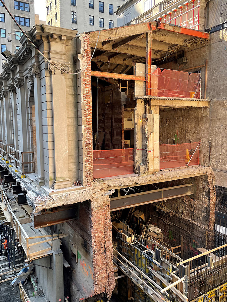
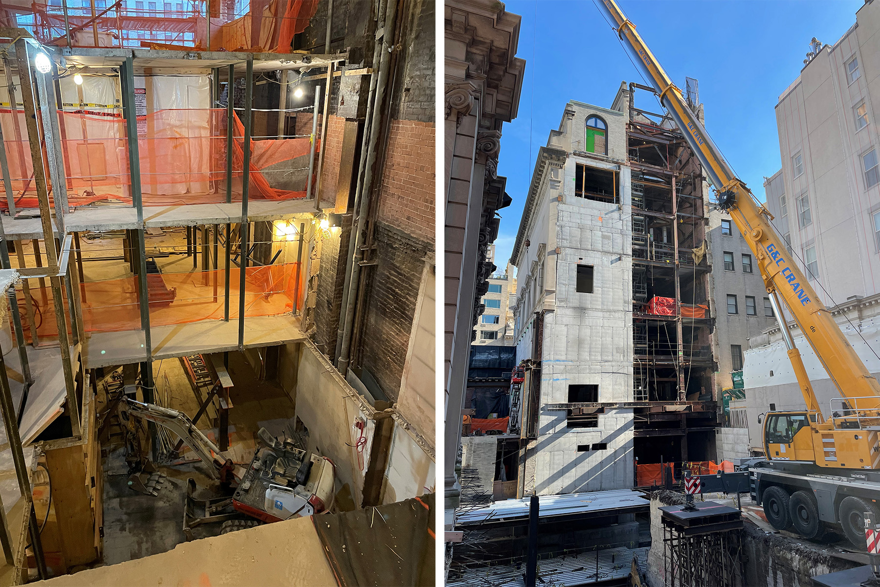
SGH’s challenge was to remove the former townhouse brick masonry foundation wall, which was below grade, while keeping intact the above-grade, landmarked, limestone-clad masonry walls at the east and south sides of the buildings.
SGH assisted the contractor with designing temporary shoring for the landmarked exterior walls, composed of cross-lot beams that ran through the Reception Hall and cantilevered over the brick masonry foundation wall that would later be removed.
The design required a concrete shear wall with a corbel to re-support the above-grade limestone-clad masonry wall and far edge of the slab. The load-transfer sequence was optimized to limit the movement of the re-supported wall and the associated risk of cracking the limestone cladding. This concrete shear wall was located adjacent to the new below-grade auditorium and required a large opening for access to the new space.
The contractor connected the shear wall to the 70th Street Garden diaphragm with a steel horizontal truss just below the new corbel. The truss transferred lateral loads collected from the new FARL addition.
Once the new shear wall was installed and the load from the re-supported above-grade limestone-clad wall was transferred to the new concrete corbel, the contractor removed the temporary shoring along with the existing east masonry foundation wall and replaced the first-floor slab with a new concrete-on-metal-deck slab and steel framing.
Above grade, SGH designed steel columns to support the new second floor. To reduce the protrusion of the columns into the above-grade space, the architect recessed them into the existing east and west masonry walls of the Reception Hall.
Because the east wall has large arched windows on both sides of the columns, the engineers designed details to support the vertical load and lateral thrust from the arches. With the columns installed, the second-floor beams and slabs followed shortly afterward.
Next, the contractor removed the existing roof structure so that a new gabled roof truss could be installed at a higher elevation. To support both the gravity and lateral loads on the new Reception Hall partial overbuild, SGH engineers designed an L-shaped shear wall and braced frame at the north end, as well as a braced frame near the south end.
To allow for a column-free perimeter, the new steel roof truss cantilevers approximately 22 ft to the south and approximately 8 ft to the east of the southern braced frame. To control deflections at these relatively long cantilevers, the plan necessitated small posts spaced at approximately 5 ft on center along the perimeter of the east and south walls that were aligned with and hidden by the mullions of the curtain wall system.
The architects designed the stairway to fit within the L-shaped concrete shear wall. SGH’s structural drawings showed a design-development level structural plan that would later be completed by the contractor’s engineer as a delegated design item. The final stair consists of multiple flat, built-up hollow structural steel stringers that are connected to the concrete shear wall by steel plates and post-installed anchors. Tread and riser plates are welded to the HSS stair stringers. The steel stair structure is clad with stone panels.
Frick Art Research Library
The FARL houses the archival library of Helen Clay Frick, who started her collection of catalogs, books, and periodicals after her father’s death to learn more about the artists who created the works he bought and to further the study of fine arts. The existing nine-story building included several floors for library stacks.
The floor structure at the stack levels consisted of proprietary concrete slabs that were 3.5 in. thick and extended to embedded horizontal steel angles spaced at approximately 4 ft on center in both directions. The horizontal angles connected to vertical angles that were hidden in the library stacks. This “stack-slab” structure transmitted its loads through the vertical angles to “strong floors” constructed from wide-flange steel beams and slag block concrete waffle slabs that were designed to support multiple levels of library slabs.
The architects extended the FARL to the south with a new nine-story addition, which houses the new Ian Wardropper Room on the first floor and a new cafe on the second floor, as well as private offices, meeting rooms, and a book-and-paper conservation center on the upper floors. In the original portion of the building, there is now room for the archival collection and future acquisitions.
The addition is situated in the 20 ft open space that was between the existing building and the north wall of the 70th Street Garden. The addition also allows visitors to connect to the new Special Exhibition Gallery and, from there, to the rest of the museum.
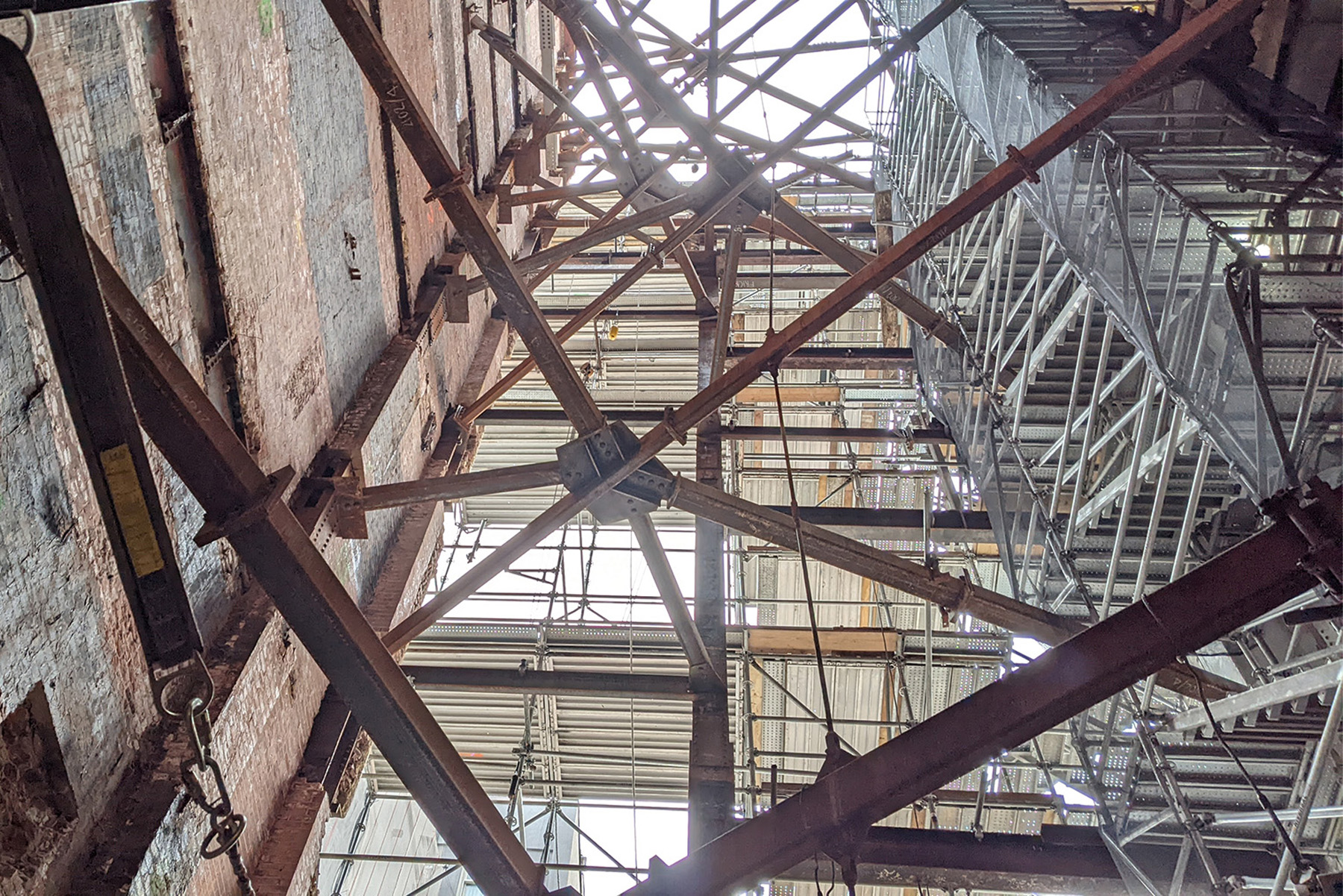
To provide access to the new addition, the existing south wall of the library needed to be removed. However, as a transitional masonry building, the lateral system for the existing FARL relied on the brick masonry walls working in conjunction with the steel superstructure. The full width of the south wall was removed, and a new half-width concrete shear wall was added in its place. This wall extends between two existing columns from the subcellar to the eighth floor.
Prior to the demolition of the brick wall and removal of beam and column encasements, the contractor installed a temporary vertical-braced frame and temporary shoring of the floor slab at each level near the new shear wall. The new shear wall encases the steel columns and the spandrel beams in reinforced concrete. SGH detailed the new shear wall with boundary-element steel reinforcement.
Furthermore, the design called for a concrete beam below each spandrel beam to provide bearing for the existing concrete slabs. At the base of the shear wall, the team designed a footing that extends the full length of the shear wall but stops just before the existing column footings. With this design, significant increases in vertical loading to the existing columns and their foundations were avoided. To resist uplift, the contractor installed four rock anchors below the boundary element zones of the shear wall.
To facilitate the removal of an exterior fire stair at the demolished south wall and improve circulation within the enlarged library, the architects introduced a new elevator and an egress stair at the southeast corner of the existing FARL building. To insert the new elevator and stair, the floor structure needed to be removed from the southeast corner of the building on all floors, including the stack slabs.
The new shafts for the elevator and stair are located side by side, which created a large opening in the floor diaphragm. The floor structure was designed with steel framing and concrete-on-metal-deck slabs that redirect lateral forces around the new openings to the existing floor diaphragms and new concrete shear wall.
The FARL had an existing bulkhead at the top of the building that housed a water tank and mechanical equipment. With the new addition, the bulkhead was enlarged to support additional mechanical equipment for the building, including a cooling tower and new boilers. The weight of the new bulkhead was supposed to be supported by the existing columns, which would transfer these loads to the shallow footings that bear on bedrock. However, many of the upper columns are supported by transfer girders at various levels of the building. Therefore, the engineers needed to analyze the transfer girders and strengthen most of their connections.
The Frick Collection’s otherwise comprehensive set of original design drawings did not contain connection information. The contractor removed architectural finishes and concrete encasement to expose the existing connections. After the rivets, angles, and plates at the connections were measured, SGH devised strengthening plans, which varied significantly because of the many connection types and specific connection configurations.
The mansion
Previously only the first floor of the mansion was open to the public. The museum planned to transform the second-floor bedrooms into new gallery spaces that display the favorite works of each family member from the collection. In addition, plans called for the Boucher Room, which once served as Mrs. Frick’s bedroom and was later moved, to be restored to its original location on the second floor.
The museum also wanted to give visitors access to the new galleries by the grand staircase of the mansion and by a pair of new elevators. The new passenger elevators are positioned at the east facade of the mansion adjacent to the Reception Hall to provide access to both buildings. The location of the elevators required new openings on the east wall of the mansion.
The stone cornice above the third floor had been supported by the existing roof of the neighboring Reception Hall since the 1977 expansion project. Since the existing Reception Hall roof structure was to be removed and replaced with a new roof truss, the cornice required new support from the mansion, which was challenging because of its eccentricity, heavy weight, and sensitivity to deflections.
The cornice is supported by a series of permanent steel needle beams through the existing masonry wall below the third floor. These beams are supported by bearing on the masonry wall and cantilever to the underside of the cornice, with a thermal break to reduce heat transfer in the steel.
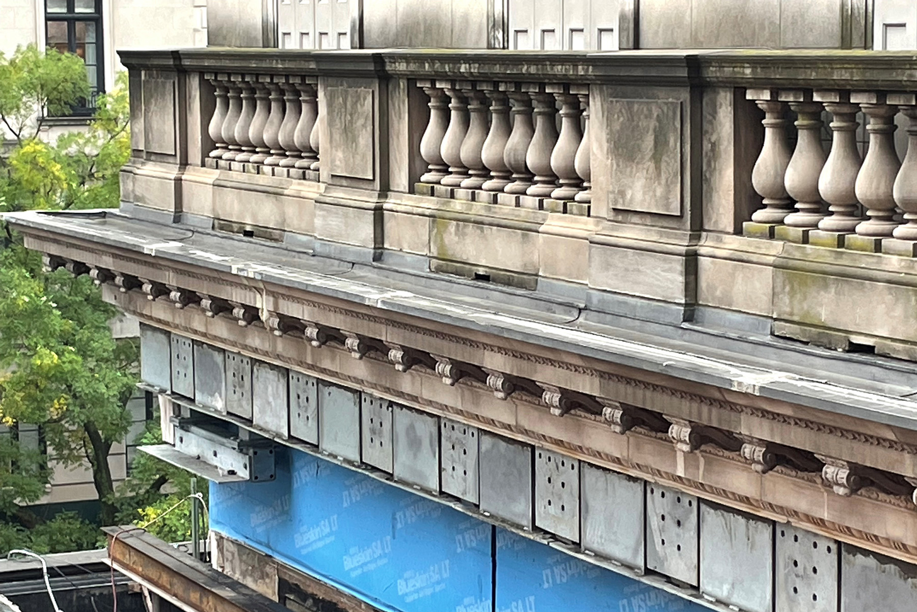
Away from the elevator shafts, the contractor extended a steel strut from the back span of the needle beams to the third-floor steel framing above. At the elevator shaft, workers connected the needle beams to new lintel beams for the opening. Between needle beams, the team designed HSS beams at the underside of the cornice to provide continuous support for the stone.
The three-story building has flat-arch terra-cotta floors that span to steel beams. The beams pocket into load-bearing brick masonry walls that are supported by shallow strip footings. To improve visitor circulation and to replace outdated building infrastructure with new systems for heating, cooling, and humidification, SGH designed numerous lintels in the load-bearing walls for doors, conduits, piping, and ducts. Some required needle beams, and others required through-bolted channels above the opening with vertical channels at the jambs.
In one case, an opening is supported through a masonry wall that was more than 3 ft thick with multiple beams framing to steel posts. The team also designed permanent needle beams to support the structure above new openings.
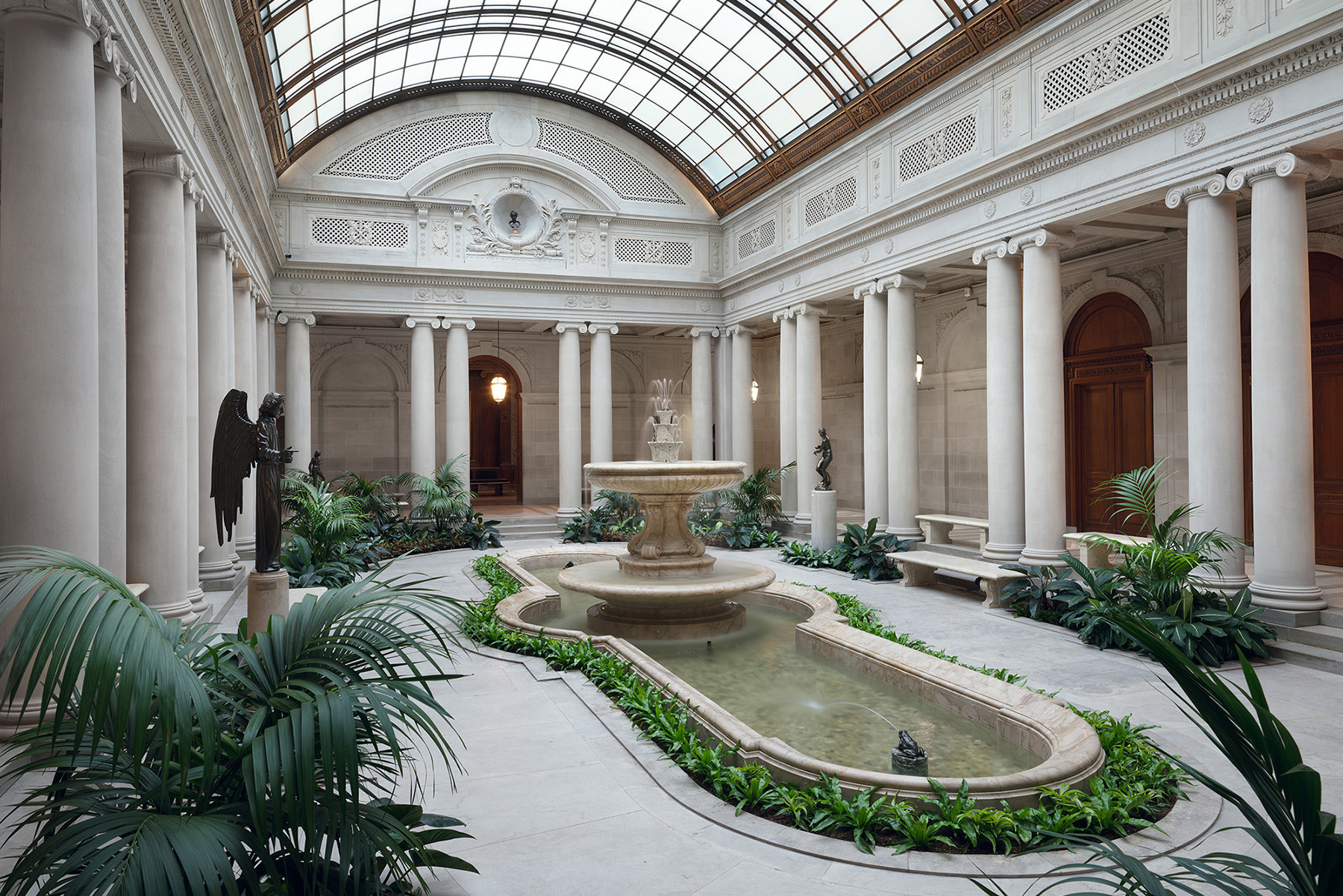
Lastly, the contractor removed and replaced the glazing of the skylights above the West, Oval, and East galleries, as well as the skylights above the Garden Court. The new glazing is energy efficient and ultraviolet protective, but it is substantially heavier than the original single-pane glazing. SGH documented and analyzed the capacity of the individual members and riveted connections of the original trusses to support the skylights’ heavier dead loads along with code-prescribed applied loads. Strengthening was added for a limited number of truss members and their connections.
Also, the original ridge beams were replaced with new HSS members that also support an abseil rail as a part of a new fall-arrest system for facade maintenance.
Creative structural solutions and understanding of archaic structural systems allowed a seamless integration of the old and new portions of the project. The new building infrastructure will provide better control of conditioned spaces, and the conservation center will enable technical analysis and preventative care of its priceless collection.
Visitors will now be able to travel throughout the museum from the interior of the mansion along Fifth Avenue to the FARL and the auditorium with ease and comfort, while enjoying brand-new amenity spaces.
Kevin C. Poulin, Ph.D., P.E., M.ASCE, is a principal, Lauren P. Feinstein, P.E., is a senior consulting engineer, and Filippo Masetti, P.E., M.ASCE, is an associate principal for Simpson Gumpertz & Heger. David A. Ribbans, P.E., M.ASCE, is a structural engineer for K2M Design.
Project credits
Owner
The Frick Collection, New York City
Design architect
Selldorf Architects, New York City
Architect of record
Beyer Blinder Belle Architects & Planners LLP, New York City office
Structural engineer of record
Simpson Gumpertz & Heger, New York City office
Structural consultant
Guy Nordenson and Associates, New York City
Owner’s representative
Colliers, New York City office
Construction manager
Sciame Construction, New York City
Mechanical, electrical, and plumbing engineer
Kohler Ronen LLC, New York City office
Geotechnical engineer
Langan
Environmental, surveying, and landscape architecture
DPC, New York City office
This article first appeared in the November/December 2025 issue of Civil Engineering as “A Masterful Evolution.”


