By Chris Matthews, MIStructE, and Neil Thomas MBE, FIStructE, CEng
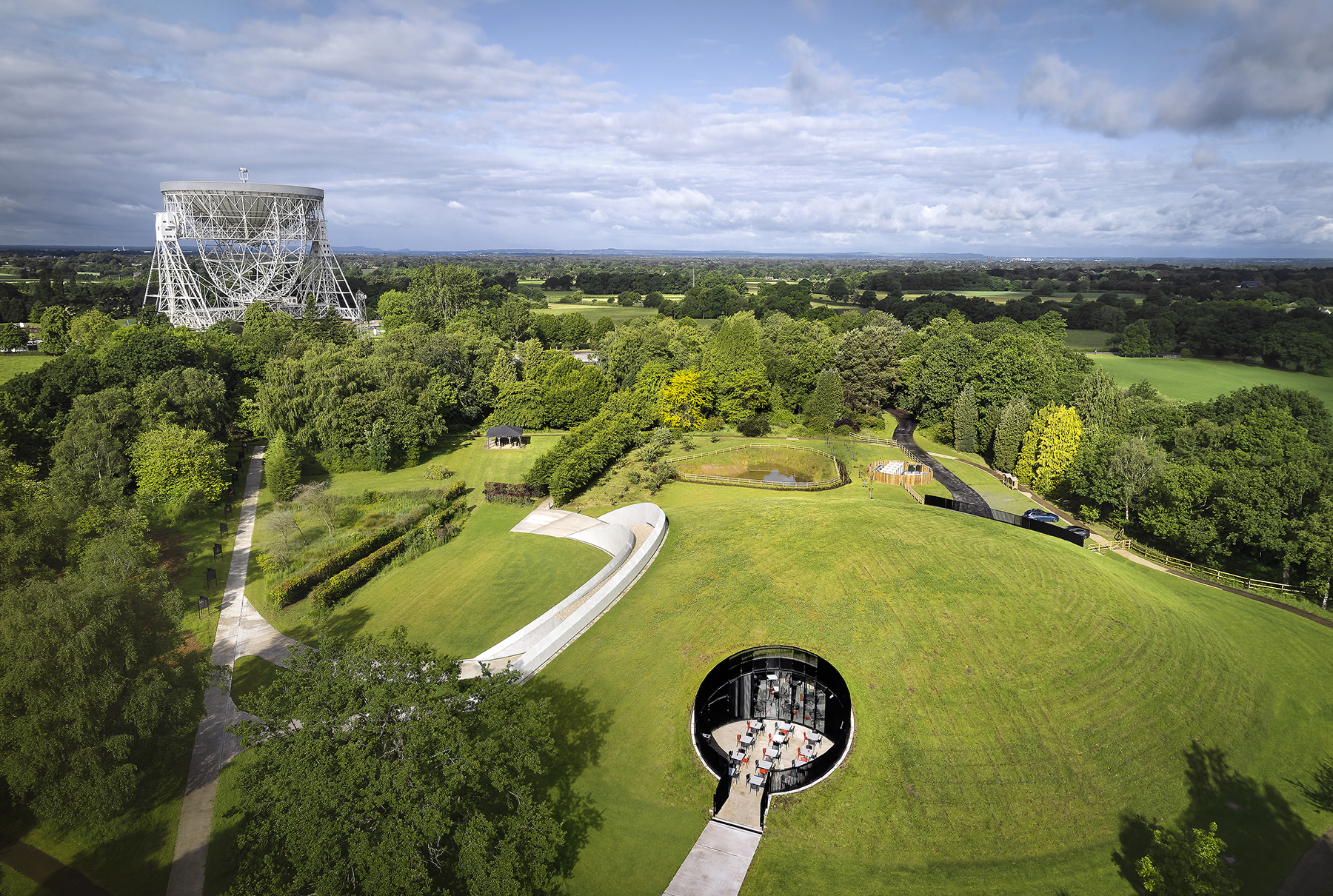
When traveling to Manchester, England, by train, it is impossible to miss the majestic Lovell Telescope rising above the horizon at the Jodrell Bank Observatory in Lower Withington in Cheshire, England. At 76.2 m in diameter, the Lovell Telescope was the largest steerable dish in the world when it was constructed in 1957.
The reuse of turret gear sets from World War I battleships demonstrates the creativity and ingenuity of the telescope’s creator, Bernard Lovell. Still in regular use, the Lovell Telescope is one of four radio telescopes at Jodrell Bank, which is the nerve center of the array of telescopes known as the enhanced Multi-Element Radio Linked Interferometer Network, or eMERLIN. Spanning 217 km across Great Britain, the network of telescopes forms a single giant radio telescope.
When architect Hassell asked Atelier One to join its team for the competition to build a pavilion at Jodrell Bank, we were honored with the opportunity to be involved in a project with a history of breathtaking scientific achievement and engineering prowess. Ultimately, our submission was selected in July 2016 by the University of Manchester, which owns and operates Jodrell Bank.
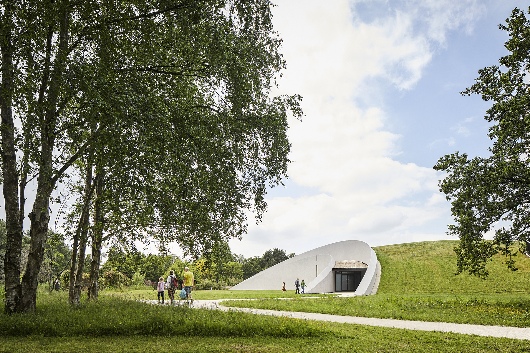
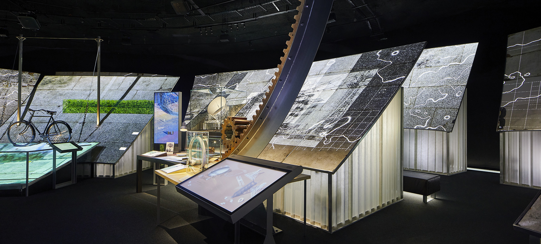
The challenge was to build a pavilion that could flexibly house an exhibition telling the telescope’s story. However, the building needed to remain low enough to avoid interfering with the telescope's operation, and it had to blend seamlessly into the extremely popular arboretum on the observatory property, which was named a World Heritage Site by UNESCO in 2019.
The resulting project, known as the First Light Pavilion, is the first large-scale shell structure to be constructed in the United Kingdom in 25 years. (In astronomy, the term first light refers to the first use of a telescope to take an astronomical image.)
Developing the dome concept
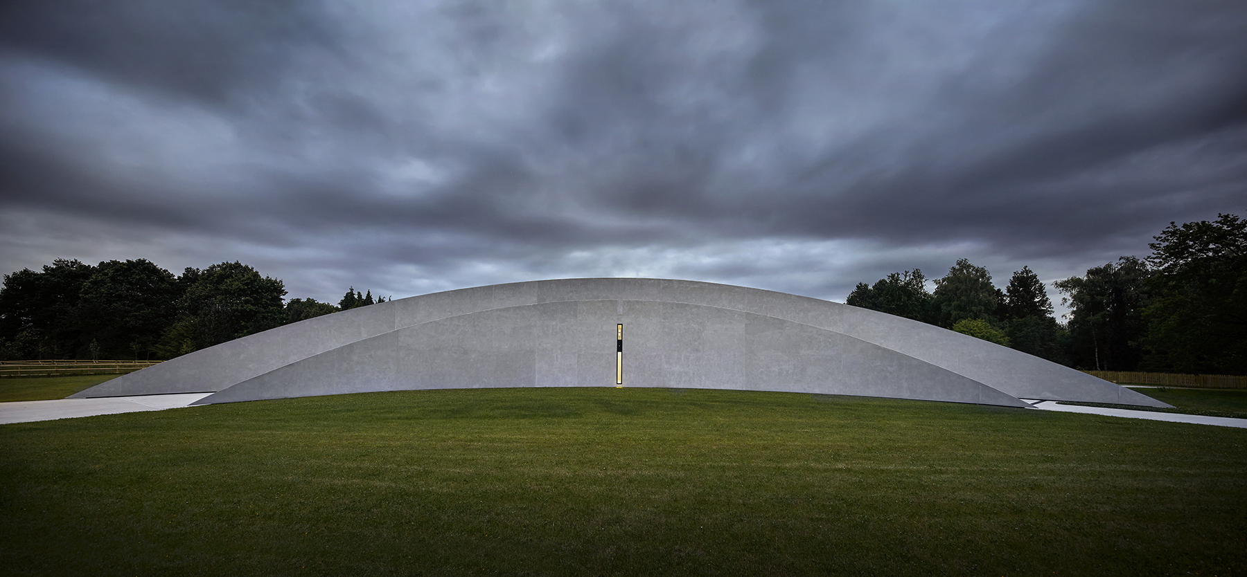
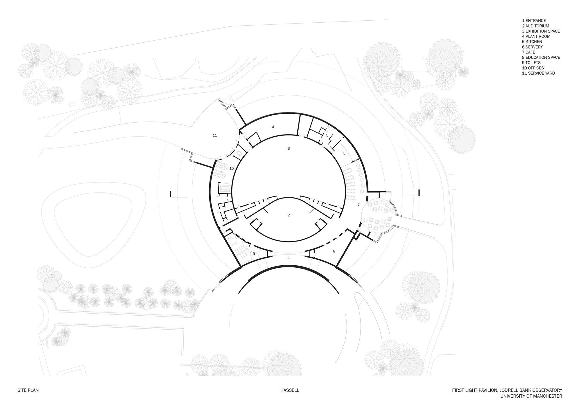
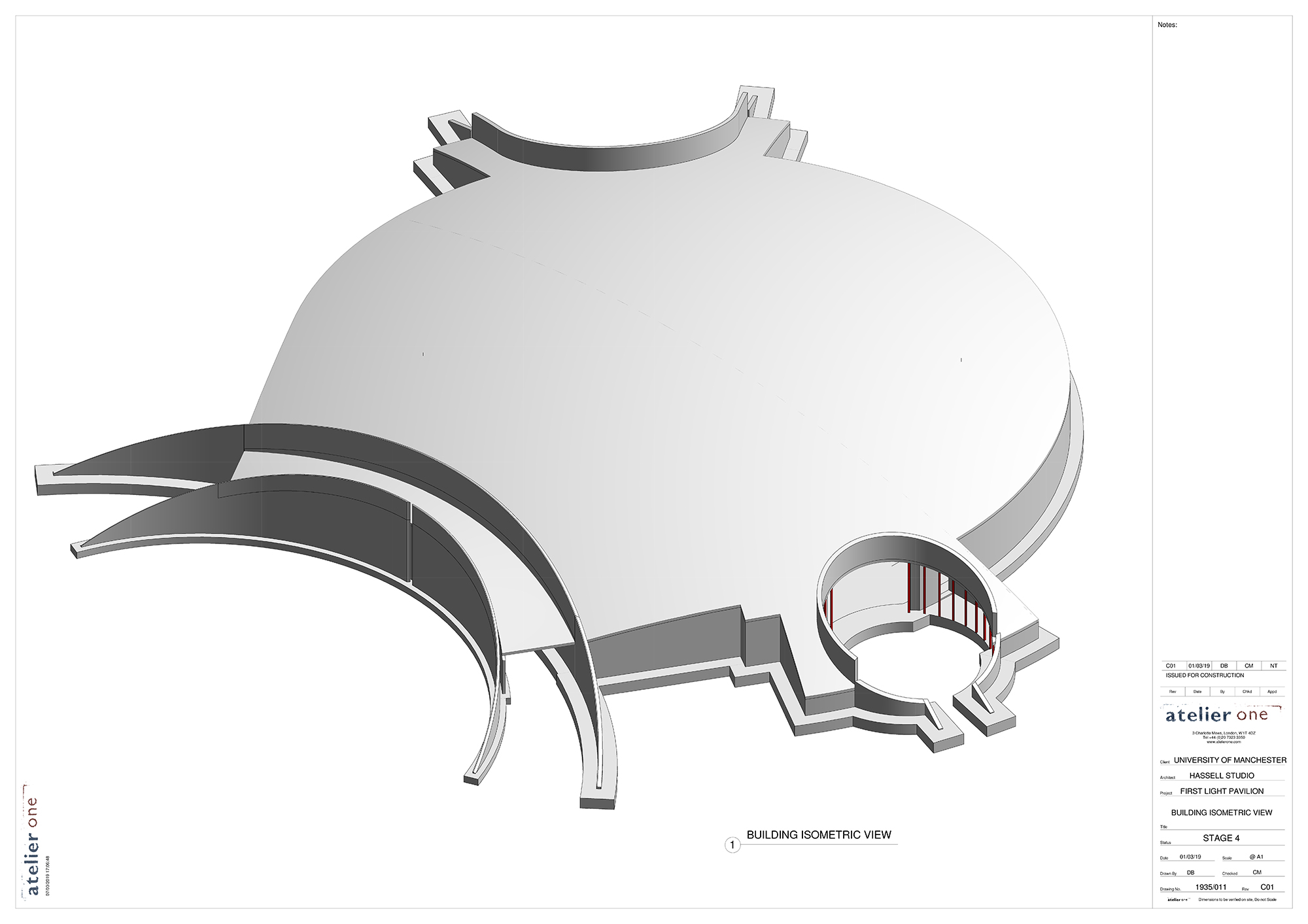
Working with Hassell and the exhibition designer, Casson Mann, we developed the concept of a 76.2 m diameter dome to match the diameter of the Lovell telescope’s dish. The concept includes a 50 m diameter shell raised on a perimeter wall that houses a 36 m by 20 m column-free central exhibition hall, an auditorium, a cafe, and office spaces. An earthwork bund around the perimeter completes the form. Cutouts facilitate access at the main entrance, a cafe seating area, and a service yard. A seating area is included within the cutout for the cafe. Covered in grass, the dome merges into the surrounding landscape.
The dome form, buried construction, and long column-free spans lent themselves to the use of a concrete shell structure. After exploring a steel version for comparison, we found it to be more expensive, and the increased structural depth compromised the key spaces. For these reasons, the concrete shell was adopted.
Few precedents to follow
Because the First Light Pavilion was the U.K.’s first large-scale shell structure in a quarter century, we had very few modern precedents to follow. We undertook an intense exercise to form a thorough understanding of concrete shells, including the study of historic masters.
To this end, we approached John Chilton, Ph.D., CEng, a professor emeritus of architecture and tectonics at the University of Nottingham and an expert in shell structures, including the works of Heinz Isler and Felix Candela, both of whom are renowned for their designs featuring thin concrete shells. With his experience, Chilton helped us gain a better understanding and advised on key points to look out for within concrete shell design and construction.
Landscaped to integrate seamlessly into the Jodrell Bank gardens, the dome had to accommodate the load of the public walking on top of it. If the dome had been designed to support full crowd loading of 5 kN/sq m across the entire structure, as specified within the design code, this would have equated to 10,000 people.
We realized that designing for such stringent load conditions would be unnecessary and uneconomic. Therefore, we considered actual visitor numbers and agreed with the client on the use of a reduced loading of 1,000 people on any half of the dome. The evaluation also considered a “worst-case” situation in which 100 people were concentrated on a 20 sq m area of the dome.
Shallow dome required
The operation of the telescope limited the height of the building, leading to a shallower dome than would typically be recommended for a dome working purely in compression. When the dome was analyzed with just perimeter support, the large outward thrust resulted in large ring tensions at the interface with the perimeter wall. These tensions would have required unfeasible levels of reinforcement and would have also resulted in large ground bearing pressures. The solution was to use the central spine wall located between the exhibition space and the auditorium as a structural support to reduce the shell thrust.
Although this solution introduced bending forces into the shell, the bending moments could be resisted by increasing the reinforcement in local areas. The hybrid between compression shell and bending active surface achieved a balance between the shell thickness, the required reinforcement, and the level of thrust forces at the perimeter. The result is a 200 mm thick curved concrete slab having a remarkable span-to-depth ratio of 1:100.
To quantify the extent that the dome form improves the structural performance, we modeled the roof as a flat slab having the same support conditions. Reassuringly, we found that the dome form reduced deflection by a factor of 40 compared to the flat slab.
Monolithic concrete element
The geotechnical conditions were poor, with soft saturated ground, so piling needed to be avoided. We therefore developed the building with a raft to minimize ground pressures. All thrust forces from the dome are resolved within the structure rather than being transferred into the ground.
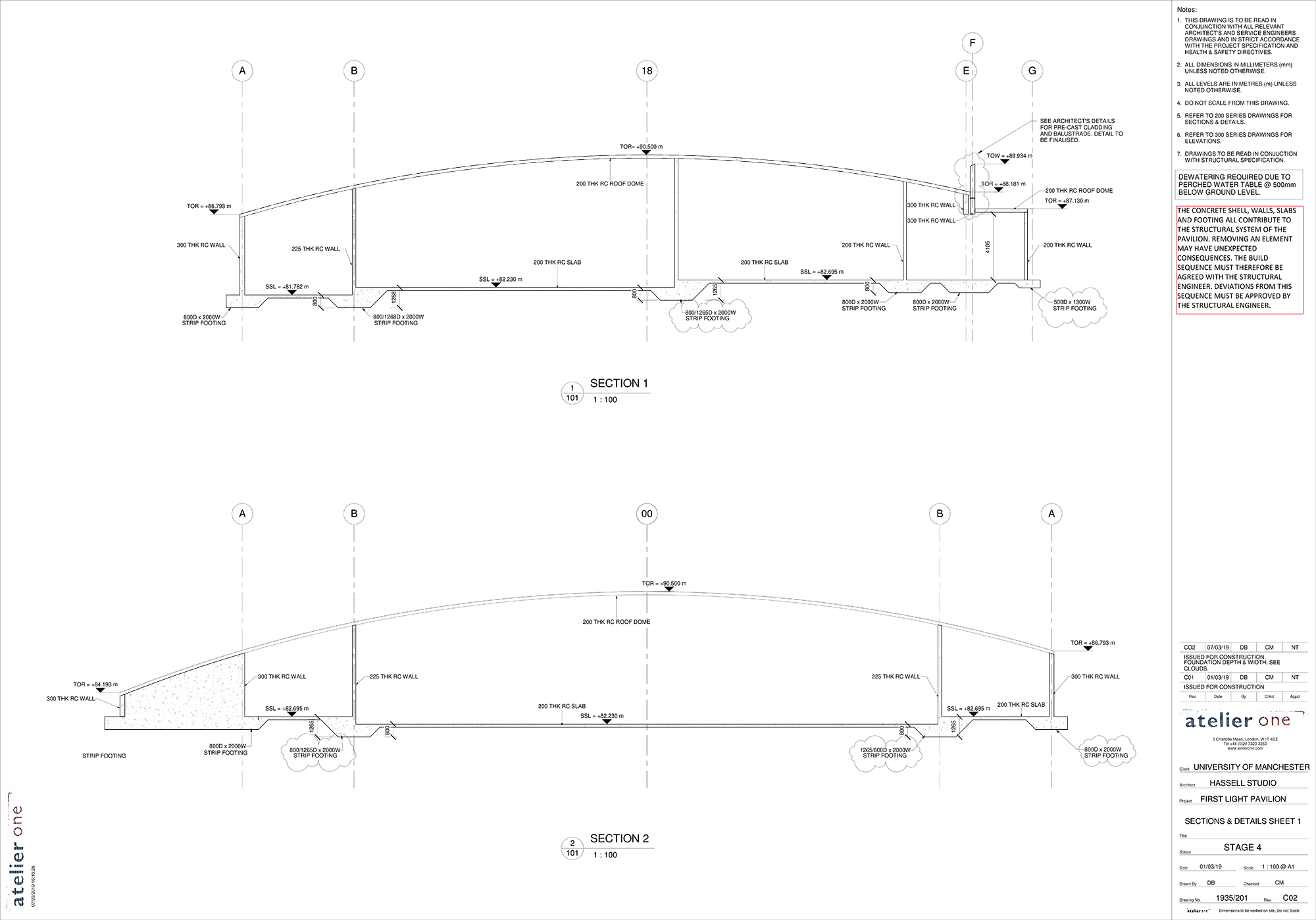
To do this, the design needed to use monolithic construction with no movement joints. Therefore, shrinkage cracking had to be considered in detail, with all reinforcement checked in accordance with the standard published by the Construction Industry Research and Information Association and titled CIRIA C766 – Control of cracking caused by restrained deformation in concrete, and the casting sequence had to be adjusted to minimize locked-in stresses.
A key challenge was the complexity of the analytical model. The entire structure works as a single monolithic concrete element. The perimeter wall pulls in the dome, and then the floor structure pulls in the perimeter wall. What would be a relatively minor change to a supporting wall in a typical concrete structure could have significant implications to the roof forces of the monolithic structure, necessitating a full reanalysis.
Minimizing the volume of concrete used was imperative to reduce the carbon footprint of the pavilion. We therefore worked extensively to make the form as efficient as possible and ensure that all concrete elements were highly utilized.
Due to the combined shell and bending action, the stresses within the dome could not be predicted by hand analysis. Due to the complexity, it was judged appropriate to conduct parallel finite-element analysis in two structural software programs, Robot Structural Analysis, from Autodesk Inc., and midas FEA NX, from Midas IT Co. Ltd. In this way, we could check the shell forces that occurred. To ensure the models meshed correctly, we had to manually mesh them before importing them to either software.
To reduce the overall reinforcement, we subdivided the roof into reinforcement zones based on the forces present. Because most of the roof works as a shell purely in compression, minimal reinforcement was required. Areas near supports and cutouts see bending moments and circumferential tensions, so more reinforcement was required in these locations.
Construction and the opening
Atelier One completed structural design for the project through stage 4, or the technical design stage, of the eight-stage plan of work developed by the Royal Institute of British Architects to organize the process of planning, designing, delivering, maintaining, operating, and using a building. The Kier Group plc then won the tender to deliver the pavilion alongside concrete specialist subcontractor Mayo Civil Engineering Ltd. The dome was cast in one day, with two shifts of workers taking 10 hours to cast 381 cu m of concrete in 3-4 m wide strips.
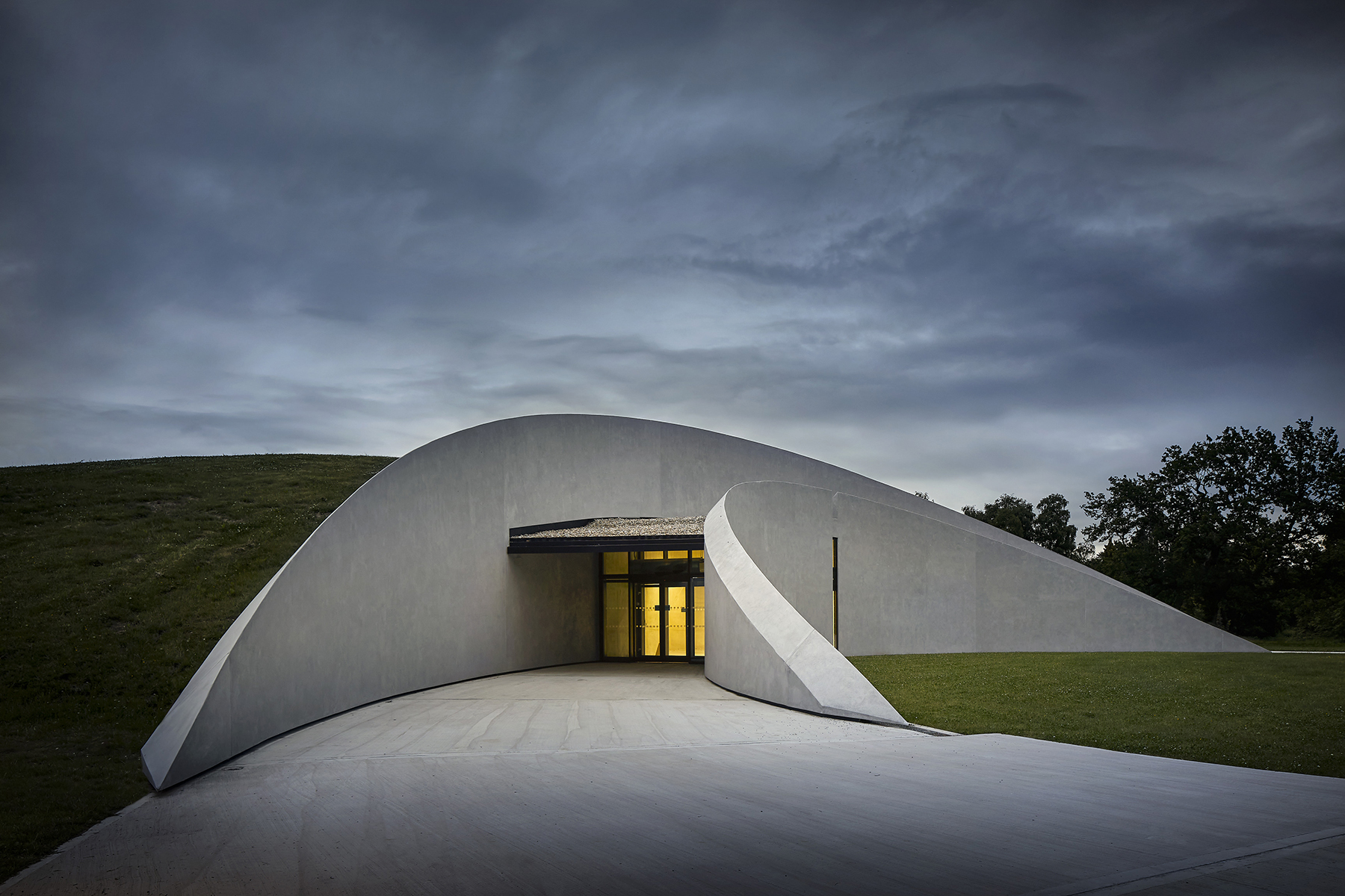
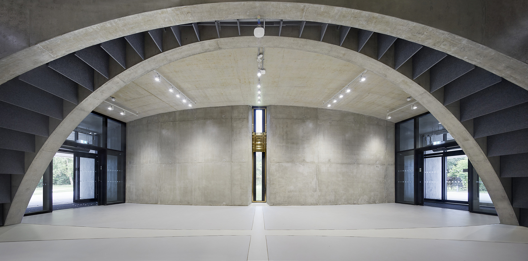
The 21.5 million-pound ($26.8 million) First Light Pavilion opened in June 2022. During the opening event, the celebrations took place within the atrium, where twin balanced arches meet the shell structure above. Here the structural concrete was not only on display but celebrated. At 1:12 p.m. on June 4, the assembled dignitaries gathered to witness the sun aligning with an aperture marking the southernmost point of the building. The sense of excitement was palpable.
We hope that just as the Lovell Telescope inspired us, the unique combination of science, engineering, and technology reflected within the First Light Pavilion can inspire a future generation.
Chris Matthews, MIStructE, is an associate director and Neil Thomas MBE, FIStructE, CEng, is the founder and director of the structural engineering company Atelier One.
Project Credits:
Owner: University of Manchester
Architect: Hassell
Executive architect: jmarchitects
Exhibition designer: Casson Mann
Structural engineer: Atelier One
Landscape architect: Planit-IE
Service and acoustic engineer: Mott MacDonald
Hydraulic engineer: Mayer Brown Ltd.
Project manager: Buro Four
Quantity surveyor: Simon Fenton Partnership LLP
General contractor: Kier Group plc
Specialty concrete subcontractor: Mayo Civil Engineering Ltd.
This article is published by Civil Engineering Online.