By Barzin Mobasher, Ph.D., P.E., M.ASCE
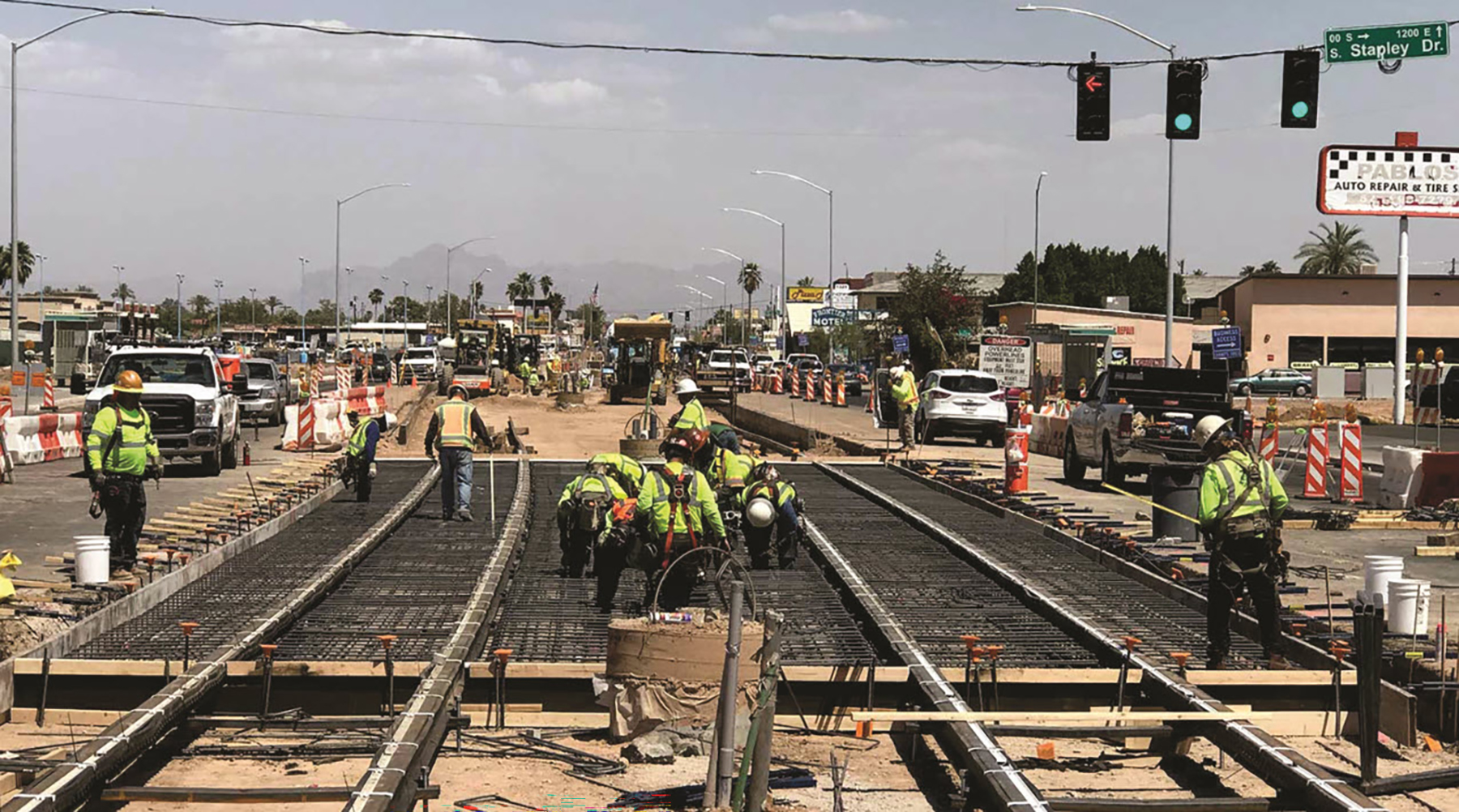
Looking to reduce project costs on a critical light-rail expansion project, Valley Metro – the regional public transit agency serving the Phoenix metropolitan area – adopted dozens of value engineering approaches. Among them was the use of fiber-reinforced concrete instead of concrete reinforced with traditional steel bars, or rebar, for the track slabs.
Use of FRC significantly reduced the required slab thickness and resulted in a much less labor-intensive construction process, decreasing construction time and costs and increasing project sustainability.
Cost savings needed
Valley Metro needed to realize significant savings during the development of its Northwest Extension Phase II project. The 1.6-mile-long extension opened for revenue service on Jan. 27, adding to Valley Metro’s existing 28-mile-long light-rail system.
The estimated costs for the extension project increased significantly during planning, prompting the value engineering process. Cost reductions for materials, labor, traffic control, and construction time were evaluated. The value engineering approach resulted in 75 options for consideration, of which 60 were accepted, including the substitution of FRC for concrete reinforced with rebar. Ultimately, the many changes realized $60 million in total savings, representing 23% of the project’s construction cost.
Validating FRC
The Structural Mechanics and Infrastructure Materials Laboratory at Arizona State University explored alternative design solutions for the reinforced-concrete track slab. The goal was to develop a design process using FRC incorporating steel or polymeric fibers, obviating the need for traditional rebar. Along with reducing slab thickness, this approach would decrease the labor involved in welding the rebar and mitigating potential corrosion caused by stray currents that result from the electromagnetic nature of the current flow in the track’s third rail.
Validation tests were conducted on mock-up specimens of two types of slabs: one using the original dimensions with reinforced concrete and another using FRC with steel fibers. Flexural tests were conducted on full sections to evaluate the performance of fibers in the track slabs, while fatigue testing was used to simulate the entire life span under service-load conditions.
The objective of these analyses was to yield valuable insights into the viability and long-term performance of the FRC system and compare FRC tracks with conventional tracks.
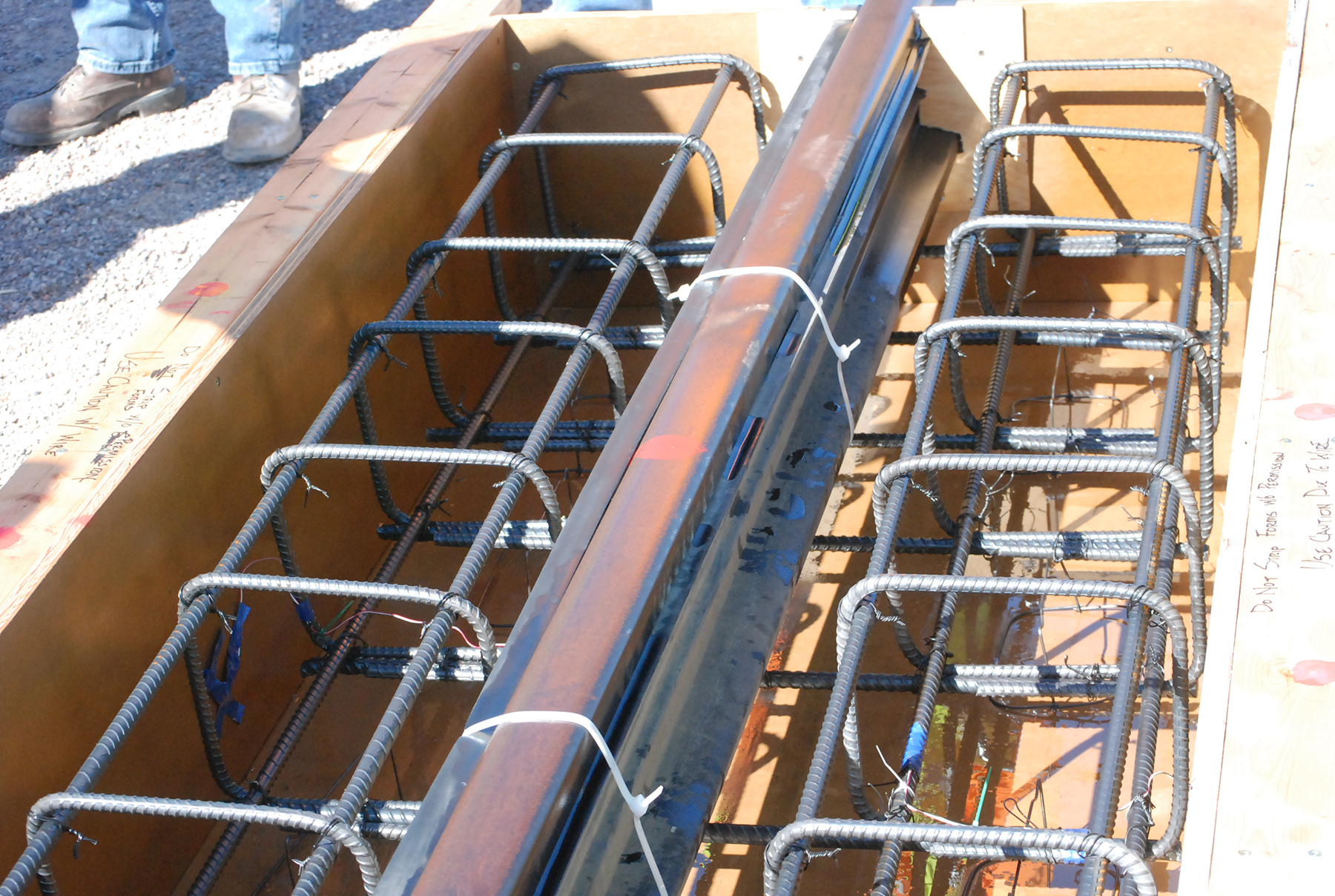
(Image courtesy of Structural Mechanics and Infrastructure Materials Laboratory, Arizona State University)
Flexural testing
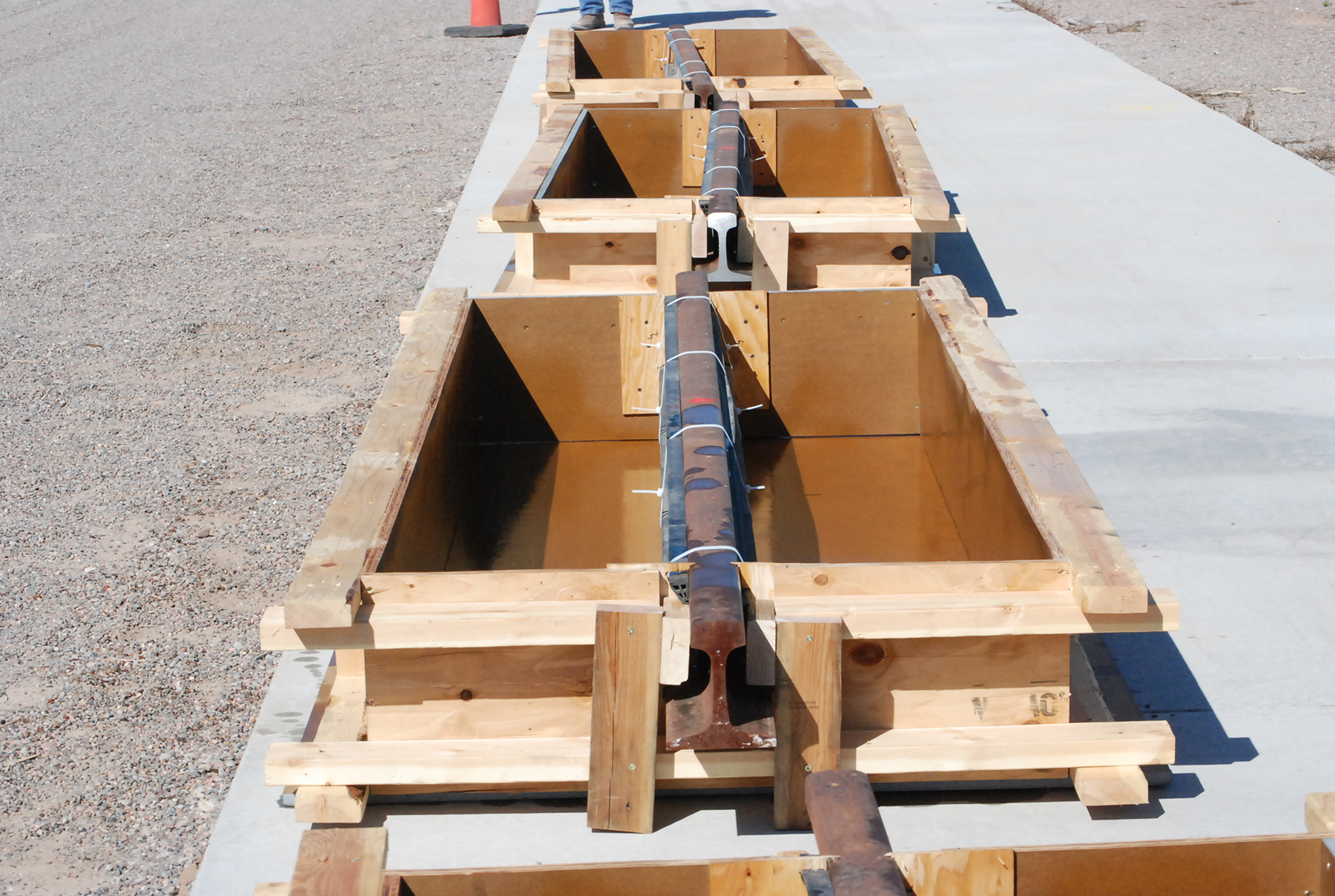
Rectangular, full-scale mock-up specimens were created for the testing. One version had conventional rebar reinforcement and was 8 feet long, 3 feet wide, and 14.5 inches deep. The other version had plain FRC and similar dimensions, except for depth, which was reduced by about 17%, to 12 inches, as no rebar cover was required.
The fiber dosage was selected based on initial design criteria for the flexural load capacity that would carry a maximum service load of 22.5 kips using a safety factor of 2. The 11.25 kips load mark was specified as the maximum service load an individual track slab would experience during its lifetime.
For the direct flexural testing, three full-scale specimens representing the control reinforced concrete and two different steel fibers were used. The FRC specimens differed mainly in terms of their steel fiber dosages. One contained 2-inch-long steel fiber at a dosage of 60 pounds per cubic yard, while the other contained fiber at a lower dosage. (The FRC specimen having the lower fiber dosage eventually would be disqualified after failing the fatigue testing, as noted below.)
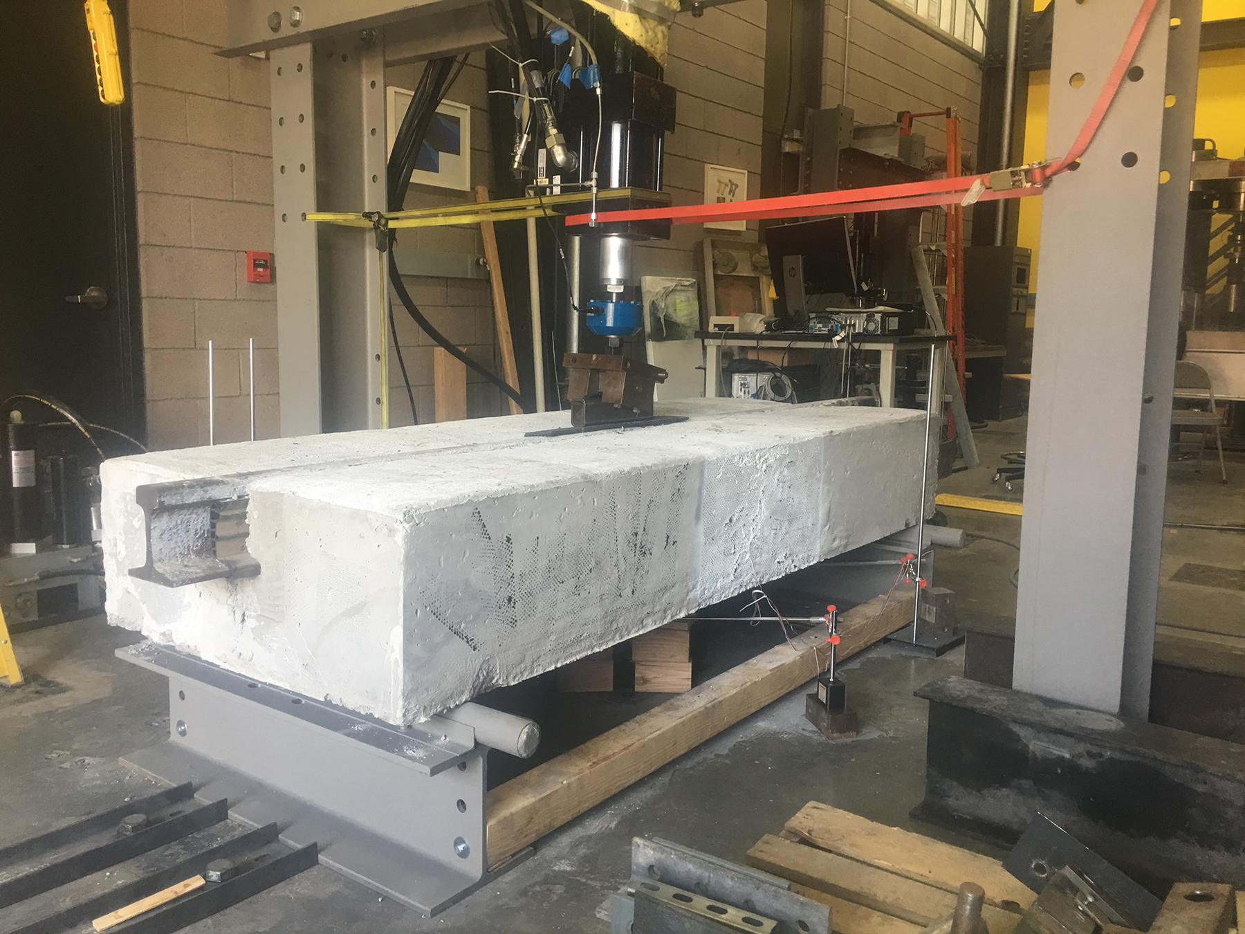
The three full-scale specimens were situated on a 7-foot-long simply supported span and subjected to a three-point bending configuration under a monotonically increasing load up to 56 kips. The point load was positioned at the center of the specimen and directly applied to the steel rail. The experiment assumed that the ground support for the slab had been lost and the slab was acting in a flexural mode with the resistance offered by the concrete. A direct comparison of the bending moment capacity between the two design types was possible.
The specimens were instrumented with four linear variable differential transformers to measure the centerline deflection. Strains on the surfaces and the rebar were measured using strain gages and the technique known as digital image correlation, which measures strain or crack openings by capturing images from the surface during the testing and using photogrammetry to measure incremental deformation between any two stages of loading. Static tests were conducted by loading the specimen until reaching the maximum capacity of 50 kips and recording the load versus deflection and strains. Deflection was determined by averaging the measurements of the four LVDTs.
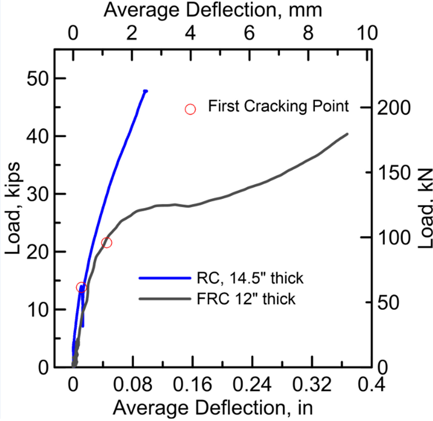
The reinforced-concrete specimen exhibited initial cracking at approximately 14 kips, beyond which the tension load was predominantly carried by the rebar. This transition resulted in a substantial increase in flexural stiffness, culminating in a maximum load of 48 kips at a deflection of 0.9 inches.
In contrast, the FRC specimen having a fiber dosage of 60 pounds per cubic yard displayed a primary crack initiation at around 22.5 kips, followed by a gradual recovery in post-crack stiffness and an increase in loading capacity. These observations indicate a higher level of ductility in the material.
The reinforced-concrete specimen had a 76% higher stiffness in the elastic phase compared to the FRC specimen, primarily due to its larger depth. Consequently, the reinforced-concrete specimen exhibited a lower cracking load because there were no fibers to suppress the propagation of microcracks and the major cracks needed to form and open to activate the reinforcement to carry load.
However, following the initiation of the first flexural crack, the rebar effectively recovered the stiffness of the control specimen and significantly controlled the deflection, surpassing the behavior of the FRC specimen, which had a more ductile response. At a deformation of 0.1 inches in a span of more than 7 feet, the load capacity of the section is still more than three times the service load.
When the elastic steel rail and FRC slab base were combined, they functioned as a composite beam. This combination yielded a hardening effect, with the steel rail still performing as an elastic beam following the initial cracking, evident with a peak load measurement of 39 kips at a deflection of 0.35 inches. It is noteworthy that the reinforced-concrete and the FRC specimen types surpassed the required service load capacity of 11.25 kips with a safety factor exceeding 2.
Fatigue loading testing
A separate set of mock-up slabs of the same size were tested by means of cyclic fatigue loading conducted by full loading-unloading cycles at a frequency of 4 hertz. This approach simulated 45 years of service life, the equivalent of a train passing every six minutes, day and night. To validate further use of the FRC track slabs, the load was almost twice the rated load of the axle of the train that would use the slabs.
For the fatigue testing, the specimens were initially subjected to a load of 21 kips to initiate cracking, before undergoing another round of testing that involved loading and unloading 2 million times within a range of up to 17 kips. During the testing, the loading-unloading stiffness of the slab was measured every 50,000 cycles and used as a measure of degradation.
The reinforced-concrete test was terminated after 500,000 cycles due to a significant loss of stiffness. Of the two FRC sections, the one with a 2-inch-long steel fiber used at 60 pounds per cubic yard met the required number of fatigue cycles. At the end of the 2 million-cycle test, the cyclic loading had degraded the slab’s stiffness by 6%. By contrast, the FRC section with the lower fiber dosage failed at 70,000 cycles.
The comprehensive full-scale flexural and fatigue tests demonstrated that using FRC in track slabs results in adequate strength and fatigue-life performance, offering a viable alternative to conventional designs. Test results indicated that using steel fibers with a dosage of 60 pounds per cubic yard significantly improved ductility and met the 45-year service life of 2 million fatigue cycles.
Significant savings
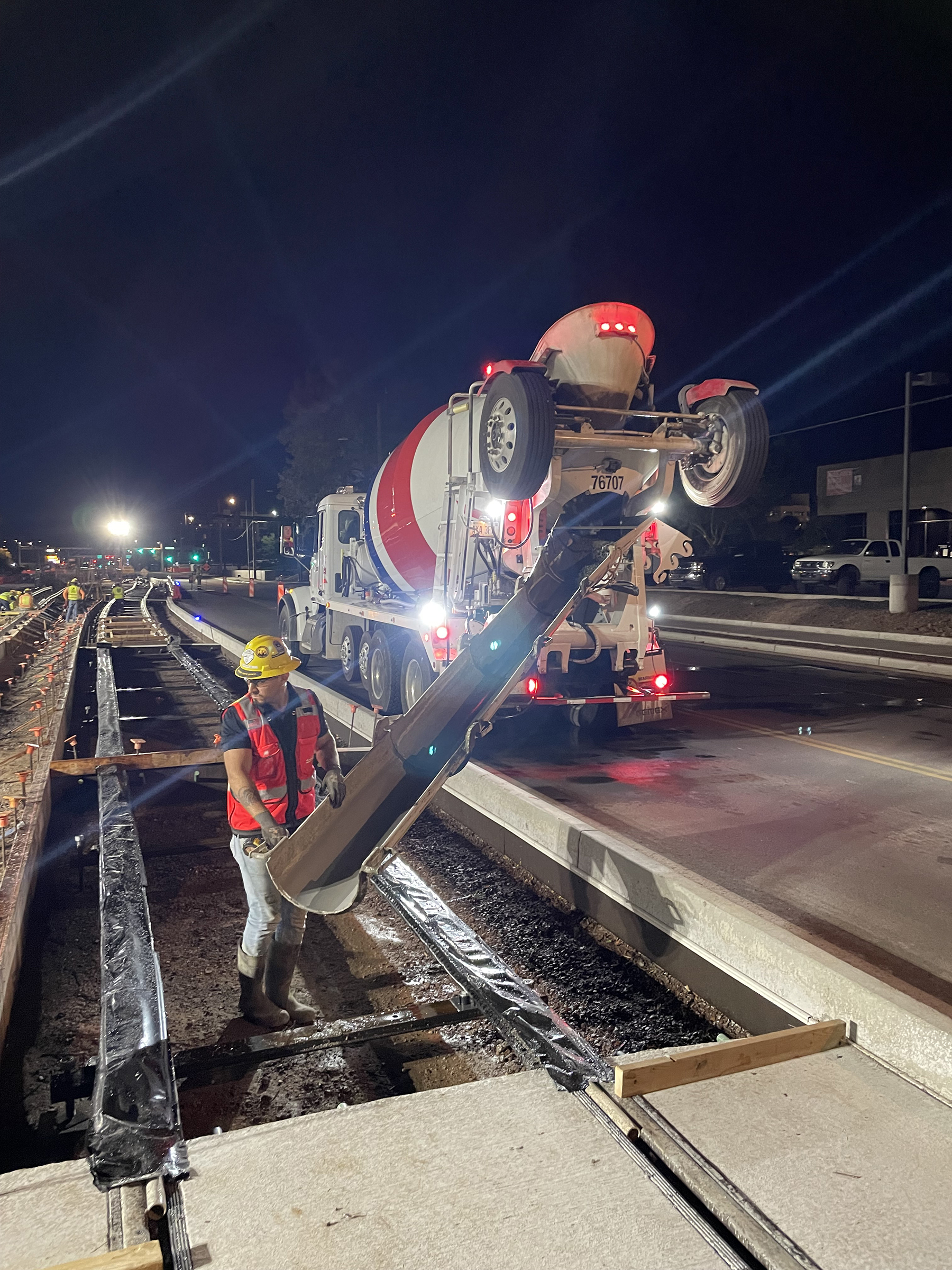
The FRC design offers enhanced constructability due to its simplified process. The fibers are batched and directly added to the concrete mixer at the plant. The resulting mixture is poured into the formwork, which requires minimal setup, making the overall construction process more straightforward and efficient.
Under the original reinforced-concrete design approach, constructing a 16-foot-wide by 1-mile-long track slab would require 184,000 pounds of No. 4 rebar and 298,000 pounds of No. 5 rebar. By comparison, the FRC design approach only required 203,000 pounds for the same dimensions. The decrease in steel use enhanced the sustainability of the project by reducing its carbon footprint.
All told, use of FRC cut construction time on the project nearly in half, from the 231 days per mile of track required by the conventional design to 121 days per mile of track. This dramatic reduction in construction time resulted primarily from eliminating the labor-intensive process of forming and placing rebar and placing concrete on a continuous slab containing rebar cages. At the same time, this design approach minimized traffic disruptions and reduced the need for road closures and traffic control devices during construction.
Cost savings on the project were even more dramatic. Whereas the original reinforced-concrete approach had an estimated per-mile cost of $17.5 million, the FRC design approach cost $5.3 million per mile, a reduction of nearly 70%.
Barzin Mobasher, Ph.D., P.E., M.ASCE, is a professor at the School of Sustainable Engineering and the Built Environment at Arizona State University. The author acknowledges the contributions of Chidchanok Pleesudjai and Devansh Patel, who are graduate research assistants at Arizona State, as well as Andrew Haines of Jacobs and Anthony Santana of the city of Phoenix.
Project Credits
Owner: City of Phoenix, Valley Metro
Design: Jacobs
Contractor: A joint venture of the Kiewit Corp. and the McCarthy Construction Co.
Slab testing and analysis: Structural Mechanics and Infrastructure Materials Laboratory, Arizona State University, Tempe, Arizona
This article is published by Civil Engineering Online.


