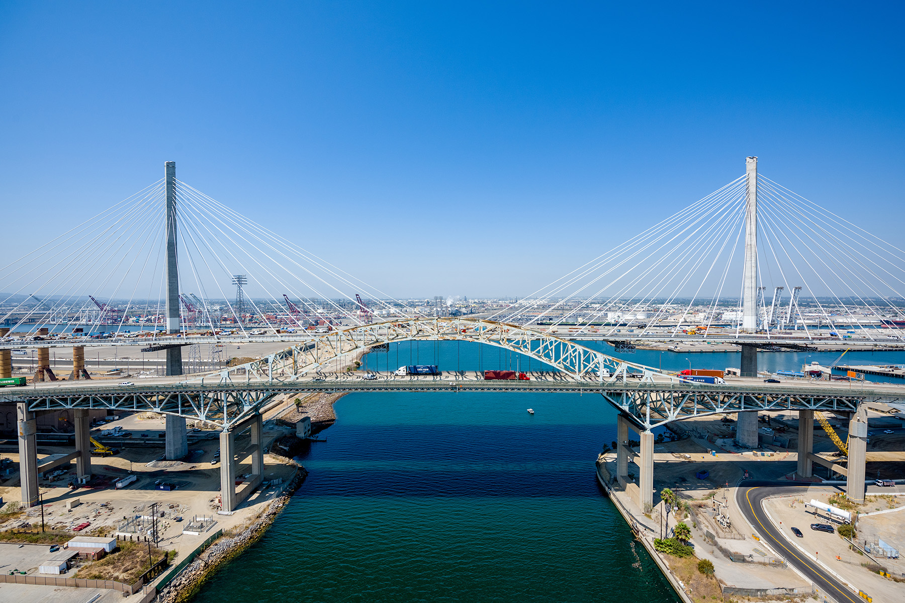
Trade at one of the world’s busiest seaports, the Port of Long Beach in California, is now enhanced by a cable-stayed bridge designed to handle the growth in cargo traffic transported over — and beneath — its deck.
Since 1968, traffic to and from California’s Port of Long Beach, one of the busiest ports in the world, has been served by the Gerald Desmond Bridge, a steel-truss through-arch bridge that was designed to carry workers back and forth from the now-decommissioned Long Beach Naval Shipyard to the city of Long Beach. By 2012, the bridge was far over capacity, carrying an astonishing 15% of all North American maritime container traffic in the form of heavy semitrucks, making it a critical infrastructure link on a regional and national scale — but vastly over its intended use.
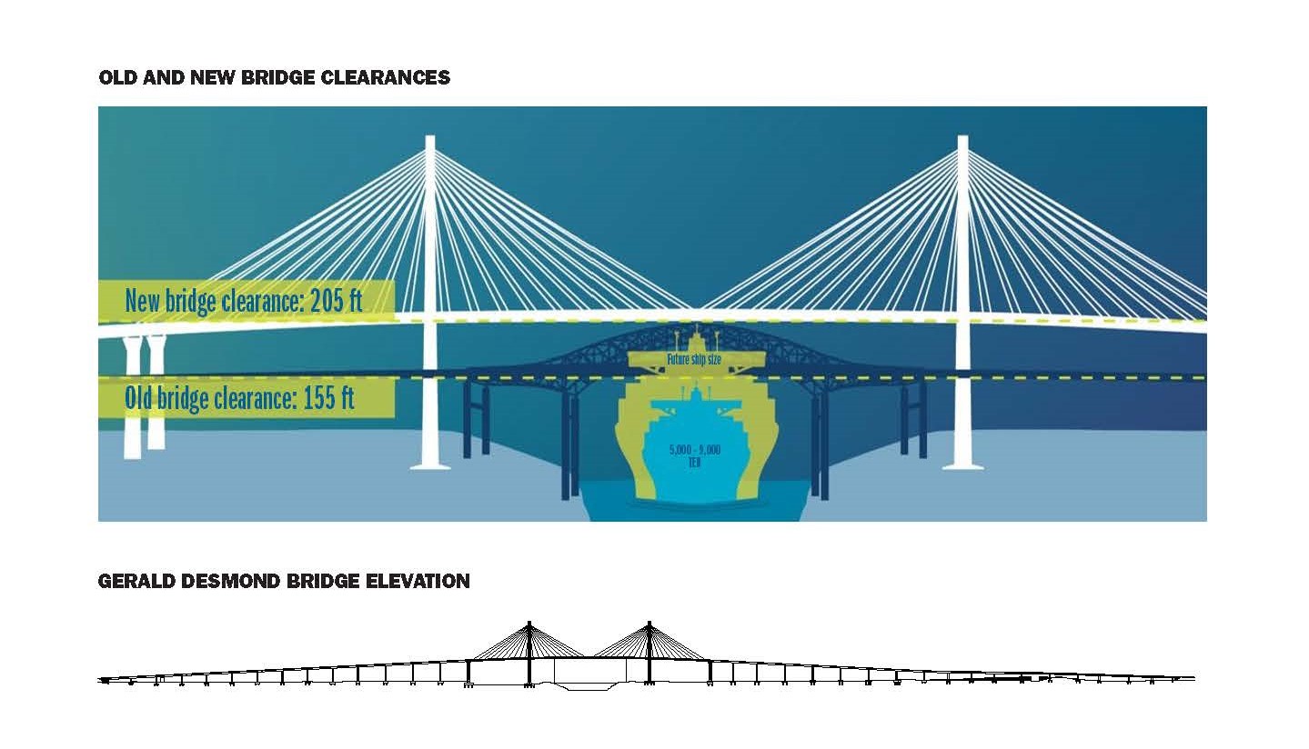
In addition to being over capacity, the bridge was also not high enough to allow the passage of post-Panamax container ships, and its two-by-two lane configuration was no longer sufficient. Moreover, the bridge was seismically vulnerable, Long Beach being located in an active earthquake zone.
So, the Port of Long Beach, in collaboration with the California Department of Transportation, began to plan for a replacement bridge that would add capacity and accommodate larger ships. In 2012, they awarded a design-build contract for the Gerald Desmond Bridge Replacement Project to a joint venture of Shimmick Construction, FCC Construcción S.A., and Impregilo S.p.A (now known as Webuild); the JV is known as SFI. Lead design services were performed by Arup in association with Biggs Cardosa Associates, BKF Engineers, and Kimley-Horn and Associates. Program management and construction management were provided by WSP.
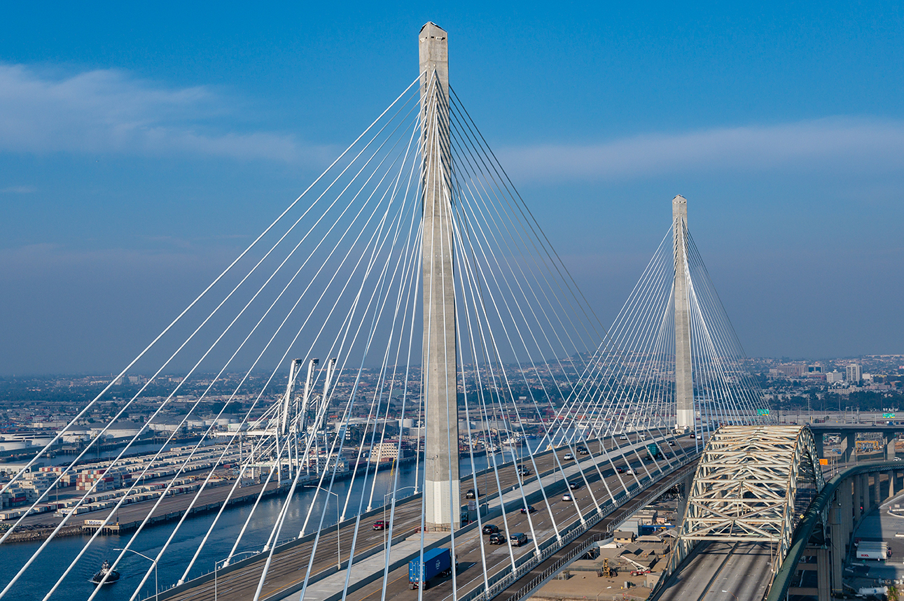
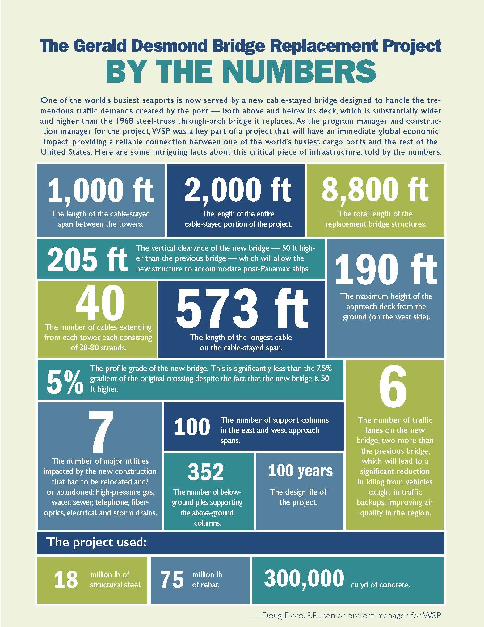
The Gerald Desmond Bridge Replacement Project involved the design and construction of a 2,000 ft long cable-stayed bridge over the Port of Long Beach’s Back Channel and roughly 2 mi of concrete box-girder approach structures. The cable-stayed main bridge is the longest structure of its type on the West Coast of the United States, the first of its type for vehicles in California, and the second-tallest cable-stayed bridge in the nation. Featuring two slender 515 ft tall monopole towers, balanced deck proportions from the back span to the main span, a two-by-three lane configuration, and moderated longitudinal slopes, the new bridge is visually stunning as well as functionally advanced.
The cable-stayed main span uses precast-concrete deck panels made composite with a steel ladder-deck framing system by cast-in-place concrete closure placements. Two planes of cable stays descend from the two monopole towers in a modified fan arrangement to support 6 ft deep, trapezoidal, closed-box edge girders. Floor beams measuring 150 ft in length span transversely between the edge girders, spaced 16 ft, 8 in. apart on center. Intermediate longitudinal stringers serve to brace the slender top flange of the floor beams. They are not composite, providing temporary support for the deck panels before closure.
The steel ladder-deck was erected stick by stick in 50 ft long balanced-cantilever segments using bolted splices. By stressing the cable stays in multiple stages, longitudinal compression was introduced throughout the composite concrete deck. This is one of the benefits of cable-stayed construction. In the case of the Gerald Desmond Bridge Replacement Project, this intrinsic benefit was augmented by the addition of substantial longitudinal posttensioning.
The critical nature of the project was reflected in the performance criteria established by the Port of Long Beach for the bridge. It was to have a 100-year design life and use a 1,000-year return period seismic event for its safety evaluation and a 100-year seismic event for its functional performance evaluation. The job site provided myriad challenges, including liquefiable soils with artesian groundwater, groundwater contamination plumes, and an extensive network of legacy petroleum extraction wells. Addressing all these issues to create a high-performance, best-value structure required innovation across the geometric, structural, and geotechnical designs.
Innovative approach
Arup designed a discreet but powerful innovation, called a Texas U-turn, to help move traffic around the lengthy approaches to this bridge. A Texas U-turn allows traffic to change direction beneath an approach structure rather than on an adjacent flyover (horseshoe) ramp. It is discreet because once completed, it is hardly visible to the occasional passerby, and it is powerful because of the enormous economy it provides to the owner in terms of construction schedule, material quantities, and cost.
The project’s preliminary geometric design called for such a flyover to carry westbound traffic seeking to exit the main roadway and cross to the southern side of the project. Arup proposed that instead of grade separating the ramp above the main roadway, the design could grade separate the turn below the main roadway via an underpass constructed through an existing embankment. This alternative eliminated the flyover structure but offered the same functionality. While common in the state of Texas, this geometric configuration is not at all common on California roadway networks.
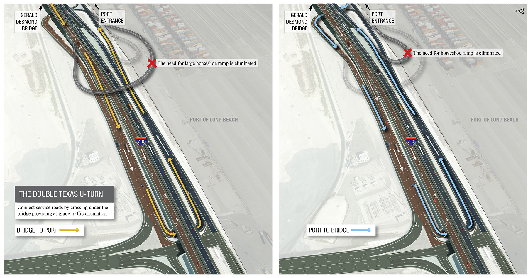
By using this Texas U-turn, project costs were reduced by approximately $70 million, in part due to the savings in quantities and schedule but also by avoiding the need to install deep foundations through a known subterranean benzene plume. Because the soil at the site is contaminated in this way, all deep foundation tailings would have required decontamination and disposal, which are costly and time-consuming. Additionally, this plan reduced the quantities of carbon-hungry construction materials and freed up several acres of land for potentially revenue-generating uses.
Among the many priorities at the bid stage, the SFI design and construction team focused on developing an approach bridge superstructure design that was optimized for the port’s objectives. Critical among these objectives were:
- Minimizing the quantity of deep foundations. In addition to reducing construction quantities, this goal would also minimize interaction with the contaminant plume mentioned previously as well as legacy oil wells located throughout the site.
- Defining an efficient approach viaduct superstructure. A constant-depth and standardized-width superstructure with long-span capability led to reduced foundation quantities and reduced formwork variations. These benefits translated to schedule efficiency.
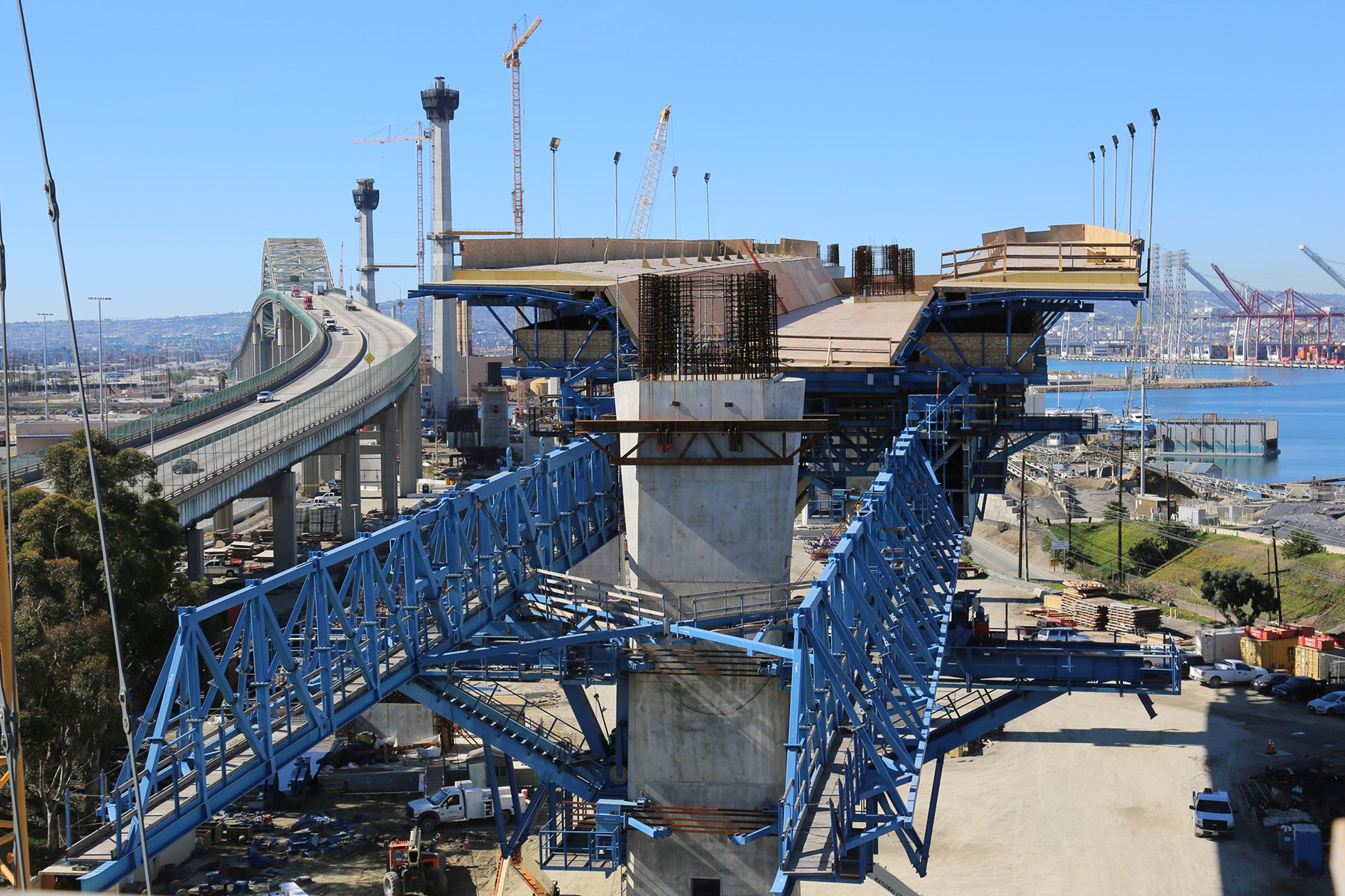
Brainstorming sessions between the design and construction teams led to a solution calling for cast-in-place sections cast on gantry-supported launching formwork and large-diameter, deep foundations augmented in capacity by pile tip postgrouting.
The selection of the approach bridge structure type took into consideration the site constraints, the height of the deck above ground, and the roadway width, which would vary from approximately 60 to 80 ft. Moreover, a constant-depth, cast-in-place structure was ideal for SFI’s construction methods. Column heights at the transition to the main-span bridge would reach as much as 190 ft, so falsework had to be minimized or eliminated. A movable scaffolding system, known as an MSS, met all these criteria.
A movable beast
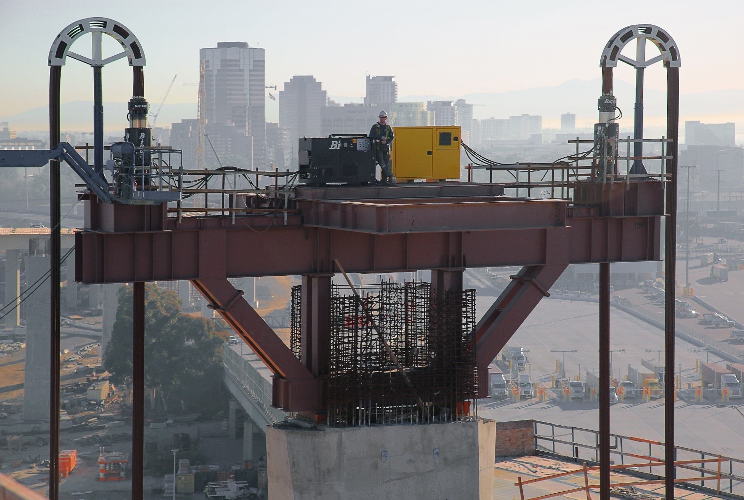
The MSS uses traditional underslung launching gantries to support formwork for single- or double-cell box girders. The MSS gantry depth and span length were optimized by suspending the tail end of the gantry from gallows perched on a fifth-point cantilever of the previous span, while the leading gantry end was supported by column brackets.
SFI procured two MSS units, essentially identical except in color, so that work could continue simultaneously on the east and west approaches toward the main-span bridge. Each MSS was delivered in more than 100 shipping containers and assembled on-site. Heavy-lift operations were used to launch or lower the MSS from then on.
Along with seismic loads, the MSS construction loads and capacity governed the longitudinal design of the approach structures. Gallows loading of the MSS on the previous span’s cantilever required two stages of posttensioning to balance short- and long-term effects. The MSS capacity limited the mass of construction loads and required specific staging of concrete casting and posttensioning between the soffit, stem, and deck.
The pier cap design was tailored to account for point loading from the heavy-lift operations of the MSSs, requiring coordination of this activity with the design team.
While the use of the MSSs offers many advantages compared with traditional falsework, it also represents a significant upfront cost. The design team made up for these costs by maximizing the lengths of the spans, thus minimizing material costs.
All about the grout
To achieve SFI’s performance goal of minimizing deep foundation footprints projectwide, the team needed to maximize the efficiency of the foundations. This required reducing the quantity of piles by increasing the piles’ diameters and increasing their efficiency with pile tip postgrouting. This scheme typically resulted in square pile groups of four 1.8 m diameter cast-in-drilled-hole, or CIDH, piles with postgrouted pile tips.
Postgrouting involves injecting grout under the base of the pile after it is installed. By effectively precompressing the pile to mobilize its base resistance concurrently with peak side resistance, the pile’s full potential is unlocked immediately.
There is no code describing the extent to which pile tip postgrouting improves pile performance, so test pile data were instrumental in confirming the design assumptions. Even with that data, extensive design documentation beyond that required for traditional foundation design was necessary. This was particularly true because Caltrans typically does not recognize CIDH pile end-bearing if the pile is constructed using tremie (underwater) concrete.
In the end, the team was able to demonstrate to Caltrans’ satisfaction that by using pile tip postgrouting, an ultimate base resistance of 1,000 psi (with displacement limited to less than 5% of the pile diameter) was possible at the pile tip elevations. This resulted in significant savings in the pile depths.
Crews tested various methods of delivering high-pressure grout to the pile tips, including tube à manchettes, known as the TAM method, and the use of specialized grout distribution plates attached beneath the pile reinforcement cage. Ultimately, a grout distribution plate approach was adopted and successfully deployed on 350 large-diameter CIDH piles.
The team’s experience demonstrated that whichever postgrouting method is selected, it is critical to control the grout rheology, temperature, injection pressure, and volume loss. Successful production depends on a grout mixture compatible with the selected delivery method and equipment. Several trial runs that consider the particular site geology and conditions as well as any plant limitations may be required to perfect the method. Even with the above considered, SFI found that redundancy in the grout-delivery system was the key to consistently mobilizing the pile tip with postgrouting and maintaining the production schedule.
Prior experience in pile tip postgrouting execution is clearly important but may be compensated for by using step-by-step validation of the construction method well ahead of the scheduled production. The benefits in terms of an efficient structure are dramatic and are in line with the environmentally focused objectives of owners such as the Port of Long Beach.
Tower treatment
The Gerald Desmond Bridge Replacement Project is located in a highly seismic area, so a parametric study was carried out using a multimodal response spectrum analysis, which established the feasibility of adopting a Type 3 global seismic design strategy, as defined by the American Association of State Highway and Transportation Officials. This meant that the bridge substructures — columns, towers, and end bents — as well as the superstructure would remain essentially elastic under the design seismic event. The team also decided to use viscous dampers between the main-span bridge superstructure and substructure. (For more details, see the sidebar below.)
The main cable-stayed section’s two monotowers are arguably the most remarkable elements of the project — viewable even from atop skyscrapers in downtown Los Angeles some 30 mi away. The towers also dominated the project’s construction schedule and the bridge’s structural performance.
The cross-sectional form of the tower evolved through a series of workshops between Arup and SFI. The most obvious starting point was a circular section tapering in a conical manner, as the circular form is visually appealing and well suited to the multidirectional nature of seismic and wind loads. In deliberating this possibility, the team reviewed the 978 ft tall towers of the Stonecutters Bridge in Hong Kong. (Read “Worth the Wait,” Civil Engineering, October 2010, pages 60-67, 78.)
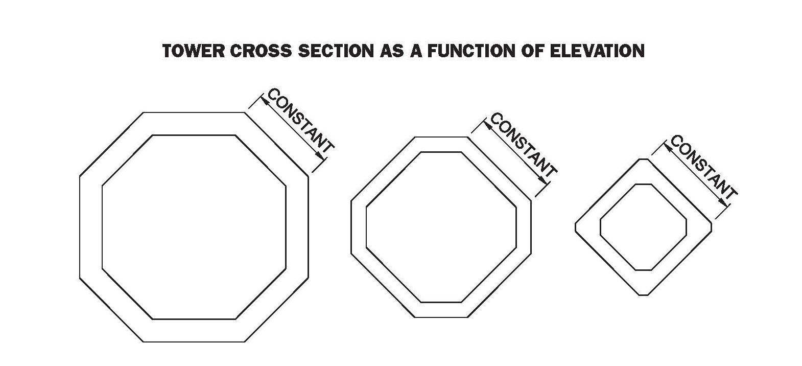
But ultimately the designers concluded that the complexity of conical climbing formwork was not economical, given the shorter height of the Gerald Desmond Bridge towers when compared with those of the Stonecutters. After further brainstorming, the Arup-SFI team settled on an eight-sided cross-sectional geometry that gradually transformed into a four-sided geometry at the tower’s top — essentially, an octagon that transforms into a square or diamond shape.
To facilitate an efficient jumping formwork system for the towers, only four of the eight sides tapered. This meant that with each jump, half the vertical formwork components remained unchanged.
The ARUP-SFI team decided to taper the faces that are orthogonal to the bridge’s primary axis. Tapering faces at 45 degrees to the primary axis would have resulted in a square geometry that is incompatible with cable-stay geometry; the fan of the cables would have intersected with the corner of the tower, meaning that some of the anchorages would pass through the section’s corner. Keeping the diagonal faces constant resulted in a diamond geometry, simultaneously resolving the geometric conflict between cable stays and the section corners and creating a unique and instantly recognizable tower form.
The octagonal tower geometry successfully merges what are occasionally competing objectives: construction efficiency and aesthetic distinction. The octagon-to-diamond solution uses light and shadow to identify the structure’s unique design at a glance while facilitating optimized construction methods and structural performance. It represents a splendid example of form meeting function and the incorporation of an architecture perspective into the structural design and construction.
PROJECT CREDITS
Owner: Port of Long Beach
Funding partner and quality control oversight: California Department of Transportation
Design-builder: Joint venture of Shimmick Construction, FCC Construcción S.A., and Impregilo S.p.A (now known as Webuild)
Lead designer and engineer of record for the main-span bridge and high-level approach viaducts, cable-stayed bridge erection geometry control, and erection engineering support services: Arup
Design of low-level approach bridges: Biggs Cardosa Associates
Roadway design: BKF Engineers
Program management and construction management: WSP
Intelligent transportation system and electrical design: Kimley-Horn and Associates
SIDEBAR
The seismic solutions
By Josh Mattheis, P.E., and Matt Carter, P.E.
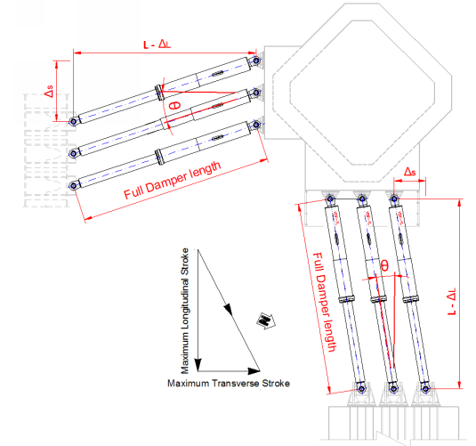
Viscous dampers were key to enabling the new Gerald Desmond Bridge to survive for 100 years despite its location in a highly seismic region of California. The design team prescribed multiple dampers arranged in sets to link the superstructure to the towers and the end bents. Each end bent has two longitudinal and two transverse dampers. Each tower has six longitudinal dampers and three transverse dampers, for a project total of 34 dampers.
Several features are included in the damper design:
- A port for recharging the fluid inside the piston chamber.
- An additional port for bleeding air from the chamber.
- A glass window through which the fluid level inside the chamber can be observed or measured via an instrument.
- Three pressure gauges for measuring fluid pressure inside the piston chamber.
- A force transducer for measuring any activating seismic event inputs.
The dampers and fuses were provided by Taylor Devices Inc., and the tests of the full-scale dampers were performed in-house and at the University of California, San Diego. The dampers were designed for the maximum number of cycles, velocity, and displacement predicted by the dynamic model, including angular distortion.
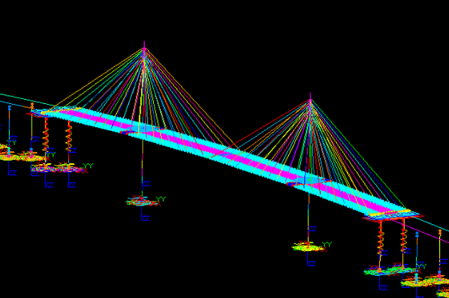
The software program LS-DYNA was used for the nonlinear time-history analysis of the main-span structure, and the analysis considered the two approach bridge frames at each end bent. (See the figure opposite, top.) Ground motions for use in the analysis were taken from the project’s seismic ground-motion report, which documented the project-specific acceleration response spectrum design curves and spectrum-compatible ground motion time histories for the safety evaluation earthquake, known as the SEE, and the lower-level functional evaluation earthquake, known as the FEE.
Within LS-DYNA, viscous dampers can be explicitly modeled. The trigger force replicates the action of the damper fuse so that the damper acts as a pinned rigid link until the trigger force is achieved.
Structural damper fuses are provided to isolate the dampers from ambient cyclic motion caused by thermal, wind, and traffic sources. The objective is to prevent movement-sensitive damper components, such as the piston seals, from experiencing premature failure due to the aggregate high number of cycles from ambient sources.
Fuses take the form of structural steel tube damper encasements with a shear ring designed to withstand forces corresponding to the demand predicted from a seismic event corresponding to a one in 100-year return-period FEE event.
Should the fuses break, the horizontal stability of the superstructure would be maintained by the cable stays and end-bent bearing friction. In this project, the end-bent bearing friction was augmented by end-bent deck tie-downs. Shear key stops were also provided in case the bearing friction were to be overcome by concurrent extreme lateral forces, such as an extreme wind event. And the fuses were designed to be replaced.
The decision to integrate the fuses directly with the dampers resulted from lengthy discussions between the design-build joint venture, SFI, and the owner. Criteria such as structural congestion, access, maintenance, and force distribution were considered. Separate and parallel fuses located in line with the dampers brought conceptual simplicity at the expense of increasing the number of structural connections and the associated maintenance and installation complications. Integrating the fuse with the damper resolved many issues while ensuring that the line of action of the fuse force was perfectly aligned with the associated damper.
The connection of the dampers to the deck was coordinated in a way that would least adversely affect the deck structure. The ideal location for the dampers is within the plane of the deck, which effectively creates a flat diaphragm. But this would introduce large openings in the deck and require an even wider deck to accommodate the traffic lanes.
For practical purposes, the end-bent dampers were attached to the underside of the end girders. The longitudinal dampers in the towers were attached to a large concrete anchor that mobilized three of the steel floor beams beneath. And the transverse dampers in the towers were accommodated in the plane of the below-deck steelwork, with local deck stiffening added by shallow steel beams.
All these positions introduce an eccentricity between the deck and the dampers, but the resulting moments were addressed in the design of the structure and connections, including additional longitudinal framing beams between the end girders and the last three floor beams at either end of the bridge.
This article first appeared in the May/June 2021 issue of Civil Engineering as “Port Connection.”