By Catherine A. Cardno, Ph.D.
With funding from the U.S. Department of Energy, the University of Nevada, Reno, in collaboration with the Lawrence Berkeley National Laboratory and faculty and technicians in UNR’s Center for Civil Engineering Earthquake Research, has designed and built an innovative, large-scale facility capable of testing soil-structure interactions. Containing a soil box that can hold up to 350 tons of soil, the system can introduce motion up to 1 g on soil and any structures that have been built within or atop it.
Known as the Large-Scale Laminar Soil Box System, it joins the existing four large-scale shake tables at the university’s world-renowned earthquake engineering testing complex.
The soil box is a one-of-a-kind testing facility, says Ian Buckle, Ph.D., M.ASCE, the soil box’s principal investigator and a professor in UNR’s Department of Civil & Environmental Engineering. “The facility will be used to advance the state-of-the art in soil-structure interaction using larger-scale structures than previously possible,” Buckle says.
Initial interest has been strong from agencies that monitor and maintain structures that are buried, such as tunnels, or have deep foundations, such as long-span bridges, Buckle says.
“The overarching purpose of this soil box is to create a very carefully controlled and repeatable experimental capability in the laboratory,” says David McCallen, Ph.D., the project leader. McCallen is a professor and Simon Wong Faculty Scholar at UNR, a senior scientist and leader of the Critical Infrastructure Initiative in LBNL’s Earth and Environmental Sciences Area, and director of UNR’s Center for Civil Earthquake Engineering Research.
Looking at this interaction will allow the earthquake engineering research community to do two things: understand the important parameters and phenomenology of what occurs between a structure and its surrounding soil during an earthquake and test, confront, and improve as necessary the existing computer models of soil-structure interaction, McCallen says.
The soil box will be used to refine the highly detailed earthquake simulations that are created using the DOE’s supercomputers as part of the EQSIM collaboration between scientists at the LBNL, the Lawrence Livermore National Laboratory, and the university.
“Certain structures — and particularly large structures or deeply embedded structures — tend to interact with the soil they are supported on in a complex way when subjected to earthquake motion,” McCallen explains. Structures at this scale might include, for example, a 20- to 30-story building built on soft soil or a nuclear power station.
This complex interaction is difficult to evaluate in the field during an earthquake “because you need to know what the incident seismic waves look like, but those are coming from under the ground. So it’s hard to measure and get a complete picture,” McCallen says.
Validating the EQSIM modeling data is crucial, McCallen notes because, “Today, almost every major structure is designed with a computer analysis of that structure and soil, so we have to make sure that our (numerical) models are accurate for replicating reality … so we can analyze the structures with high confidence.”
In addition, by “using DOE’s cutting-edge supercomputers, the longstanding goal of computational modeling of a full regional-scale, rupture-to-structure sequence is becoming a reality,” Buckle says.
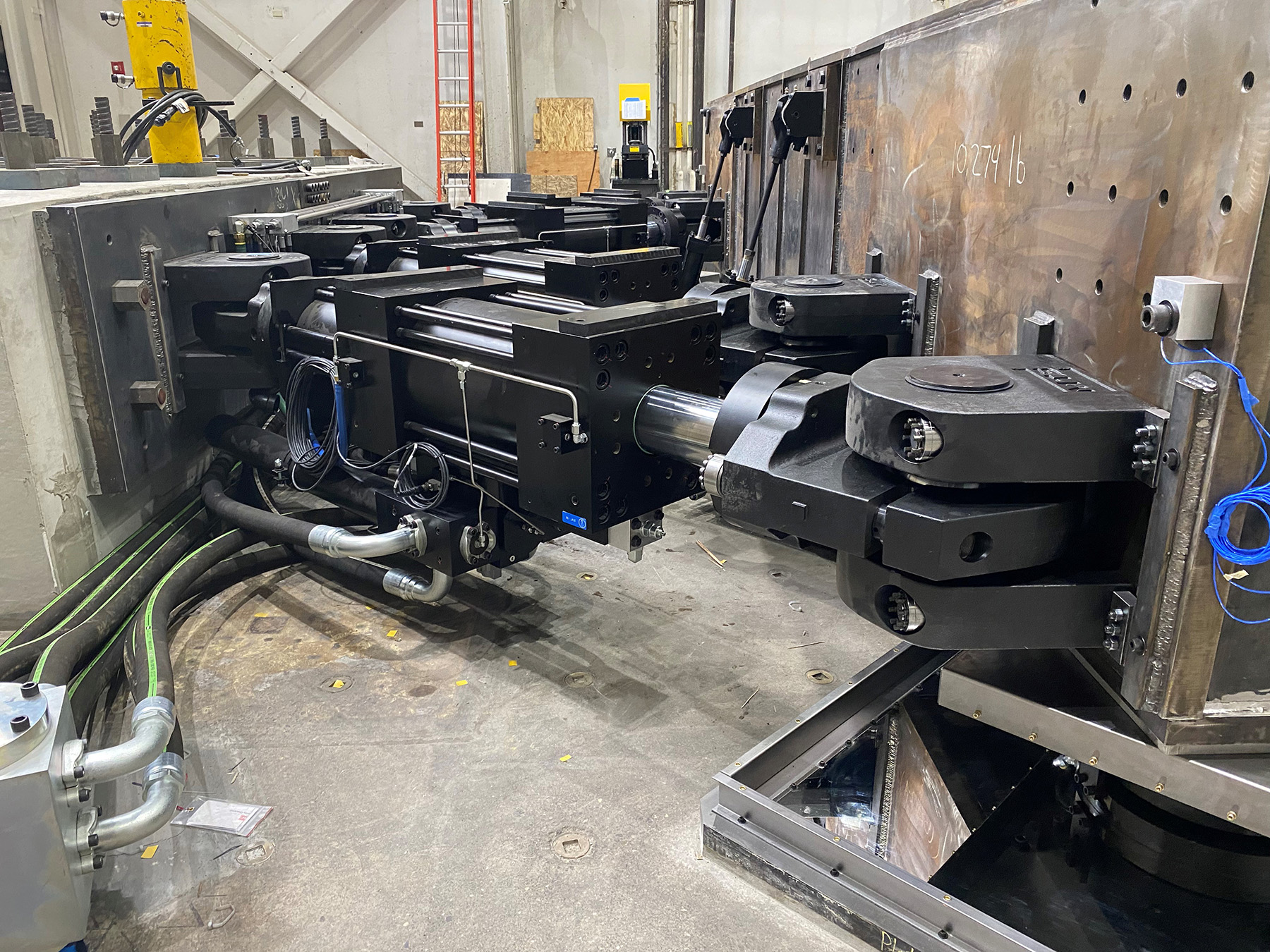
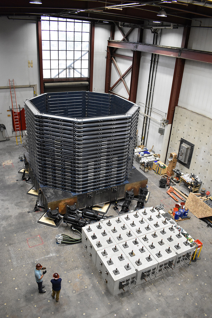
The laminar soil box system includes an eight-sided, open-top box with a 22 ft by 22 ft footprint. Each side or wall is approximately 10 ft in length. The box is bolted to a custom-built 24 ft by 24 ft steel platen that floats on hydraulic bearings and is mobilized by eight 220 kip hydraulic actuators. These actuators are capable of exciting up to 400 tons — up to 350 tons of soil and up to 50 tons in structural elements — for input motions up to 1 g acceleration in the north-south and east-west directions simultaneously, according to Buckle.
The platen can move plus or minus 12 in. on the hydraulic bearings for a total of 24 in. peak-to-peak movement.
And, notably, the walls of the soil box deform under movement. This is so that they can shift dynamically under the actuators’ forces — and as the platen moves — and not introduce additional loads on the soil contained within the box.
When testing is underway, it is a sight to behold as the walls deform, McCallen says. “When you’re in the lab and you shake this hard, you tend to have this flight instinct because it’s so massive (and) it’s so noisy,” he says.
The soil box walls are composed of individual steel frames formed from identical, hollow structural steel tube sections. Each frame is connected to the frames above and below it with a set of elastomeric bearings that can move plus or minus 4 in. A total of 408 of these bearings are used in the entire soil box, and their design varies throughout the height of the walls. These bearings can be removed or rearranged to accommodate the changing needs of the soil in a fully loaded box so that the box stiffness for a test exactly matches the soil stiffness, according to McCallen.
The individual frames are also grouped to form three segments that enable the box to be used at approximately 5 ft, 10 ft, or 15 ft tall, depending on a test’s needs, according to McCallen.
The soil box is filled using a hopper attached to an overhead crane, so that each layer of soil is added and compressed before the next level is added. This will permit a variety of soil types, densities, and compositions to be created, monitored, and tested in situ, ranging from loose to very dense soils. And different types of sensors can be carefully placed throughout the soil.
The box “cannot accommodate submerged soil in the current configuration, (but) that could be accomplished in the future by adding a waterproof box liner,” says McCallen.
Any structures built atop the soil in the box can extend up to 10 to 15 ft above the height of the walls and will also be fully fitted out with sensors, according to McCallen.
The system was conceptualized, designed, and constructed at UNR in just five years. “We went through the challenges of getting through the pandemic once we started construction, and then most recently we’ve gone through the challenges of the supply chain,” McCallen says.
“There are literally just thousands of fittings and pipes and so forth in this (system) for all the hydraulics. And things that before the pandemic were just (available) off the shelf, during the pandemic suddenly became things that we had to go out and hunt for and wait for. So that was a non-trivial part of this (process),” McCallen explains.
The system is available for the earthquake engineering community, including DOE researchers and scientists across academia and industry.
“It’s important for (the) DOE and the National Nuclear Security Administration to invest in this work to ensure that the large, complicated, one-of-a-kind facilities we build are designed to protect the country’s research, defense, and energy-generation needs,” says James McConnell, associate principal deputy administrator for the NNSA, who was quoted in material distributed by UNR.
“The findings have an added benefit of helping engineers and architects in industry and the private sector build a wide range of earthquake-resilient structures,” notes McConnell.
Catherine A. Cardno, Ph.D., is the editor in chief of Civil Engineering Online.
This article first appeared in Civil Engineering Online as “Shake table dedicated to soil-structure interaction completed.” It appeared in the January/February 2023 issue of Civil Engineering as "Shaking Soil."