By Christopher Blust, P.Eng, CEng, MIStructE, David Watson, CEng, MIStructE, and Charlotte Robinson
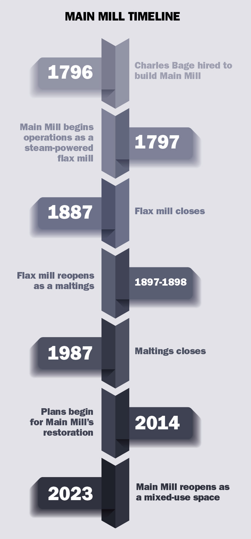
The Main Mill at Shrewsbury Flaxmill Maltings, completed in 1797 in England, is considered the world’s first cast-iron framed building. Often referred to as the grandparent of skyscrapers, its pioneering iron frame construction is the inspiration for today’s modern, steel high-rise buildings. A design team employed a bottom-up, first-principles approach to preserve the building and its history.
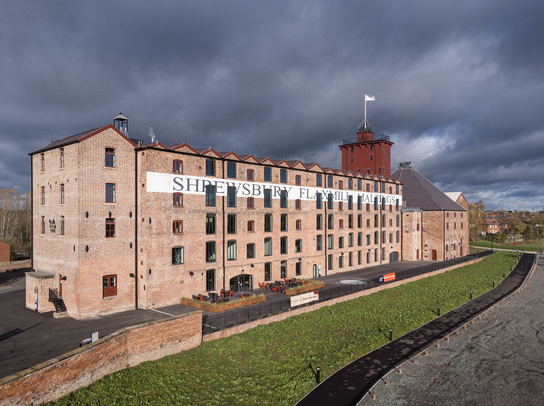
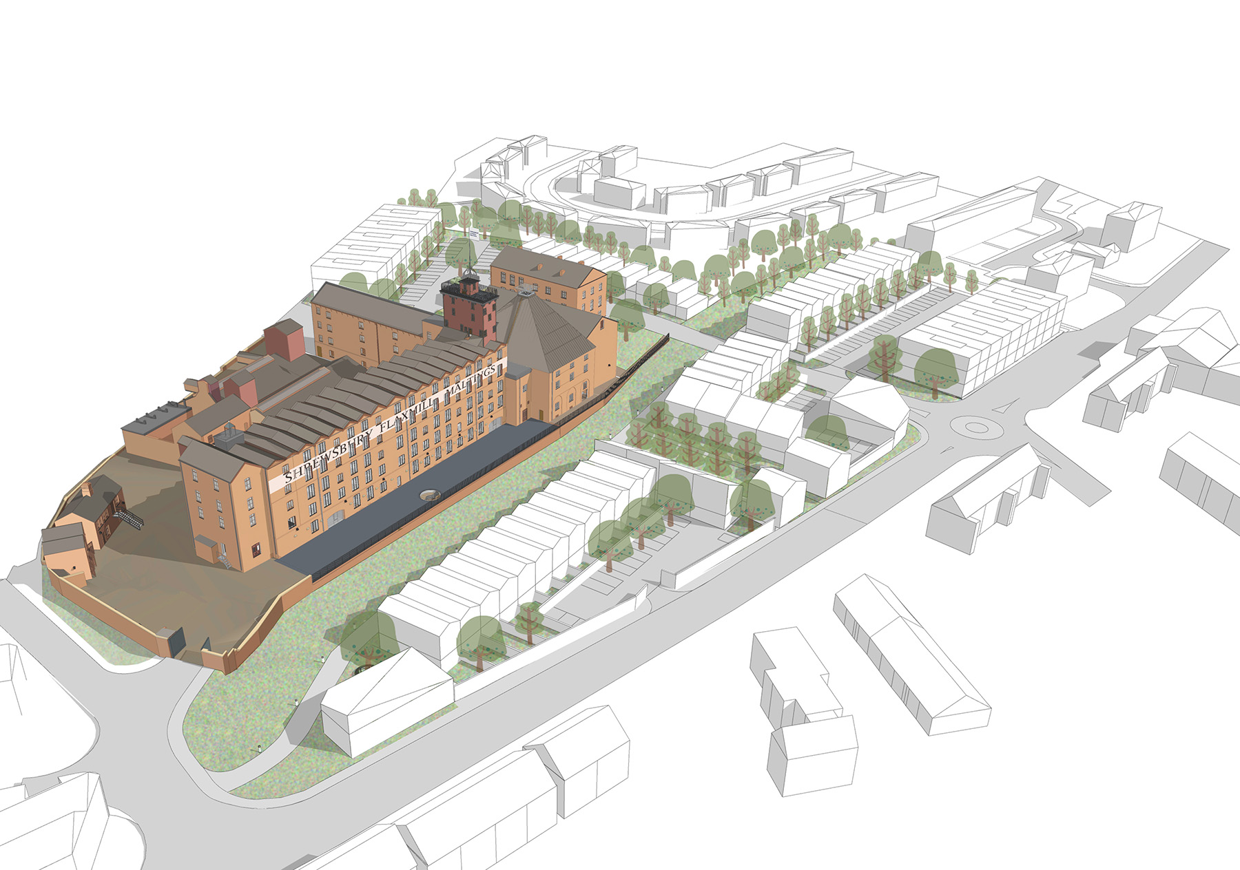
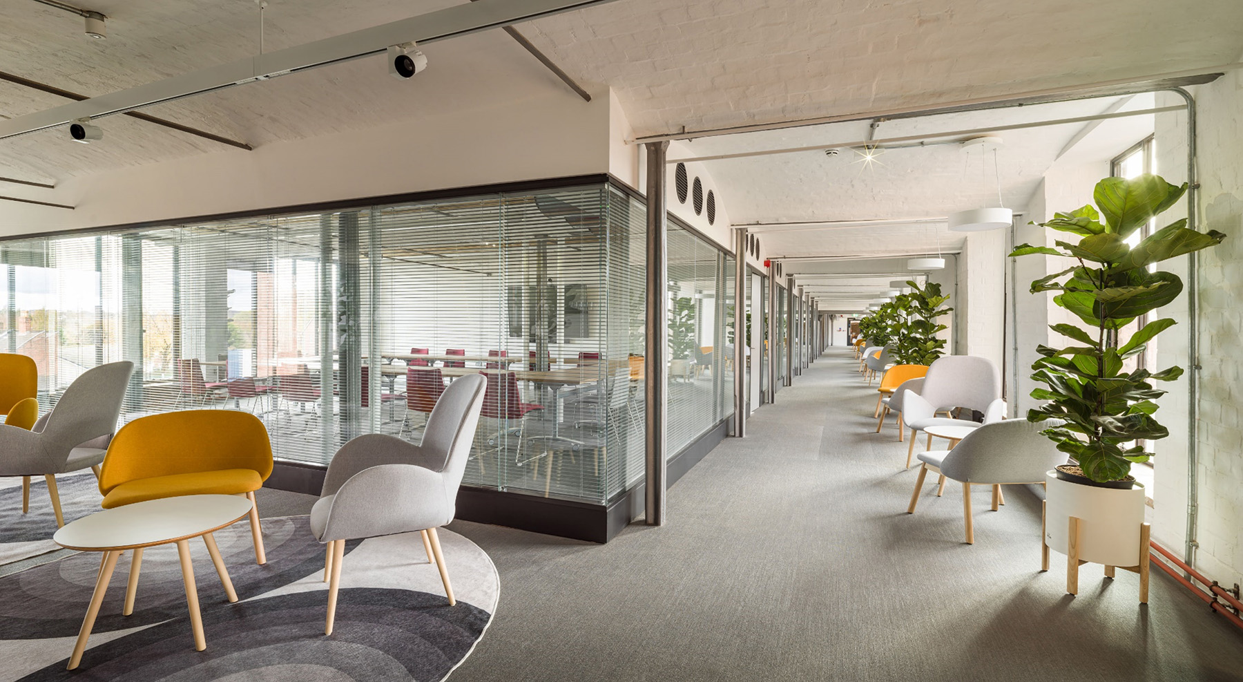
The Main Mill at Shrewsbury Flaxmill Maltings has, at the age of 226, begun its third life: as a mixed-use building comprising office space, a visitor center, and a cafe. Near the border of England and Wales in the town of Ditherington, which is a suburb of Shrewsbury in England, the overall site encompasses a series of mills and buildings, with the oldest built between 1797 and 1812.
The Main Mill, then known as Ditherington Flax Mill, and later as Shrewsbury Flax Mill, with its five stories, was the first building to be completed on the site. It is now a protected historical building in the United Kingdom.
Though an efficient means to mass-produce foods and materials, mills at the time were extremely susceptible to fire due to the accumulation of combustible materials such as dust, lint, and oil. At any moment, a mill could be destroyed by fire, but a less-combustible solution was on its way.
Near Shrewsbury, in the village of Coalbrookdale, iron master Abraham Darby III was pioneering the smelting of iron using coke. Employing this cutting-edge technology, in 1779 he cast the ironwork for the world’s first known iron bridge, aptly named Iron Bridge. Emboldened and encouraged by Darby’s success, industrialists and their insurers began to contemplate using this revolutionary material in mill construction, as it was seen as a “fireproof” equivalent to timber columns and beams.
Fast-forward 17 years to English architect Charles Bage who, acting as engineer on the project, used cast iron to construct the entirety of the internal load-bearing frames for all the mills at the site. His fireproof design saw him substitute traditional timber beam and columns for equivalent cast-iron sections. However, the use of cast iron in those early days was at best experimental and relied on limited physical testing and simple calculations.
Historical analysis has revealed the cast-iron elements delivered a factor of safety much lower than would be recommended once formalized guidance emerged in later centuries. Yet despite these limitations and other challenges, the mill’s frame endured.
The flax mill operated with heavy machinery for 90 years. It was then converted into a maltings (or malt house), which involved infilling the original windows to achieve the dark, damp conditions required for barley germination, opening by 1898. A cement-based screed was added to the floors and large openings were crudely formed to accommodate the heavy steeping tanks. Its life as a maltings, however, ended in 1987.
The building sat empty and derelict and in desperate need of repair for many years. However, the building was too important to lose, so Historic England, a British architectural preservation organization, together with the Shropshire Council and the Friends of the Flaxmill Maltings, devised a plan in 2014 to breathe new life into the structures on the site.
The Main Mill now encompasses a museum space on the ground* floor and office space on the upper levels — a white-collar factory to replace the industry of old. (*Editor’s note: In the United Kingdom, the ground floor denotes what would be considered the first floor in the United States. We kept the U.K. floor numbering system in the article.)
Having successfully reopened to the public last year, the Main Mill stands as a testament to what can be achieved at the extremes of adaptive reuse.
The existing structure
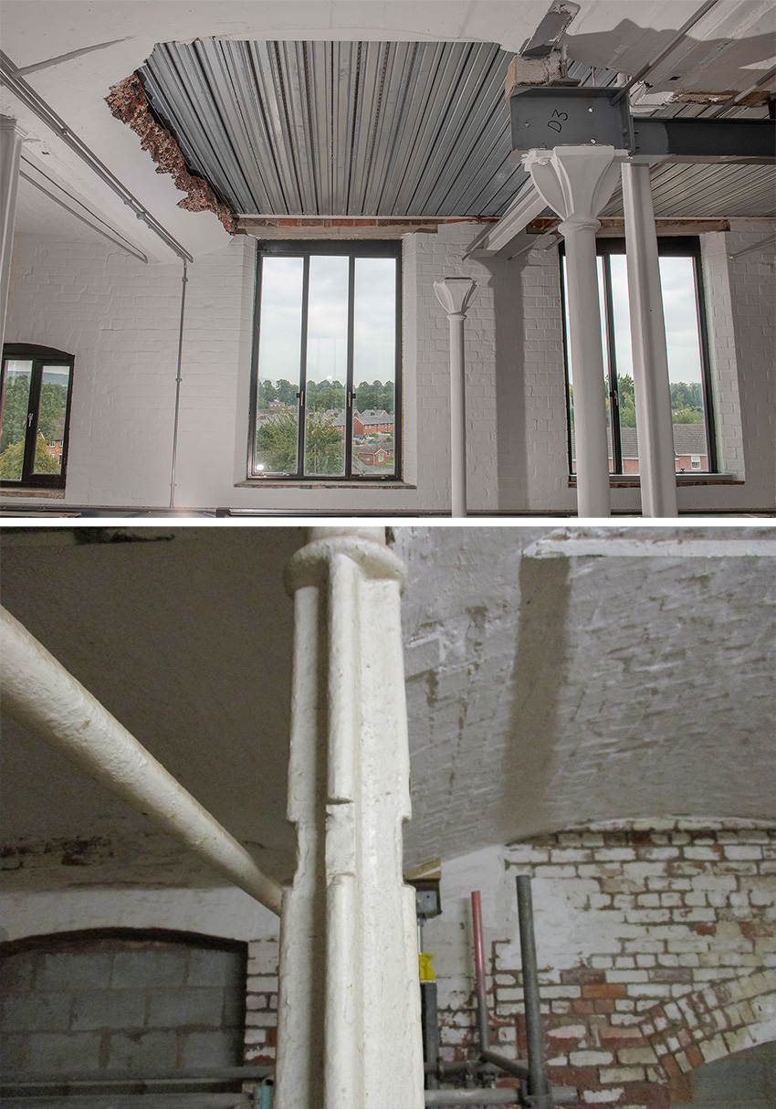
The Main Mill is approximately 64 m long and 12 m wide. The building comprises perimeter masonry walls bearing on shallow strip footings and masonry vault floors supported on the internal cast-iron frame. Oak rafters formed the roof pitches, sheathed with sarking boards.
The original masonry walls were constructed with “great” bricks — measuring 240 mm by 110 mm by 100 mm — which are significantly larger than today’s standard bricks. Lime mortar was used in the original wall construction, with later alterations increasingly making use of cement-based mortar.
The mill’s cast-iron elements are complex and inventive with some inspiration derived from timber construction. The columns are cruciform in shape, which was thought to be the strongest cross section at the time, and this configuration circumvented the complexity of internally voided castings. The columns are tapered to be thickest at midspan. Split-head columns at the ground and third floors accommodated the mill’s power transmission system.
The beams have a triangular-shaped bottom flange. This shape provided more material in the tension zone, thus supplying more capacity in regions that were sagging while also providing a bearing for the incoming jack arch floor. There was no top flange, although the web increased in height toward the midspan locations, reflecting the bending moment profile.
While the beams are continuous, no corresponding increase in depth is seen at the support locations. The splices in the beams were achieved through bolted end plates, which was a novel concept for joining cast iron. The connections between the beams and columns were made possible by simple housings cast into the beams, into which the spigots at the column ends fit.
Defects and decay
While the cast-iron frame construction was innovative for its time, in the 21st century, it would not do. The major issues were the deteriorating frame and the timber embedded within the masonry facades. A complete overhaul of the mill was needed to bring it up to today’s standards.
There were five major issues to address within the structural proposals:
1. An overstressed and damaged cast-iron frame. The maltings conversion added 23% more self-weight to the system, thereby further reducing already-slim factors of safety. A number of columns had been damaged as a result of crude modifications undertaken to accommodate machinery during the flax mill and maltings phases. This reduced the capacity and overall resilience even further.
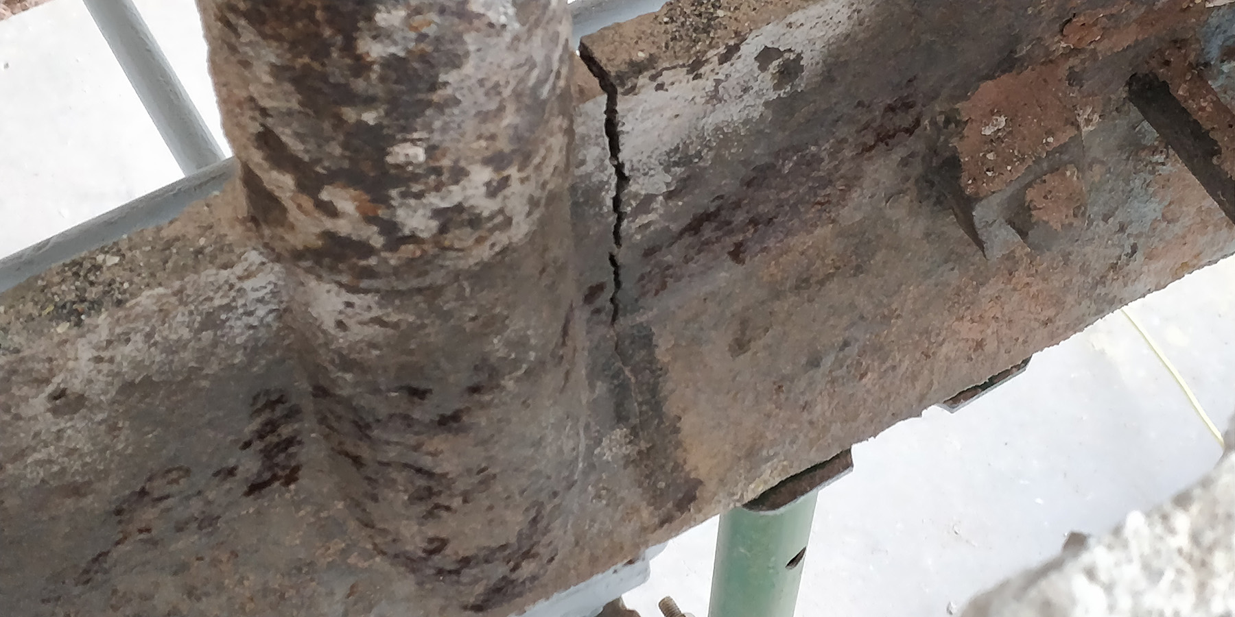
2. Differential settlement. Significant differential settlement had occurred throughout the life of the building between the walls and internal support columns. This movement caused the cast-iron beams to crack in a number of locations, compromising the capacity of the beams to support floor loads and act as tying restraints to the perimeter walls.
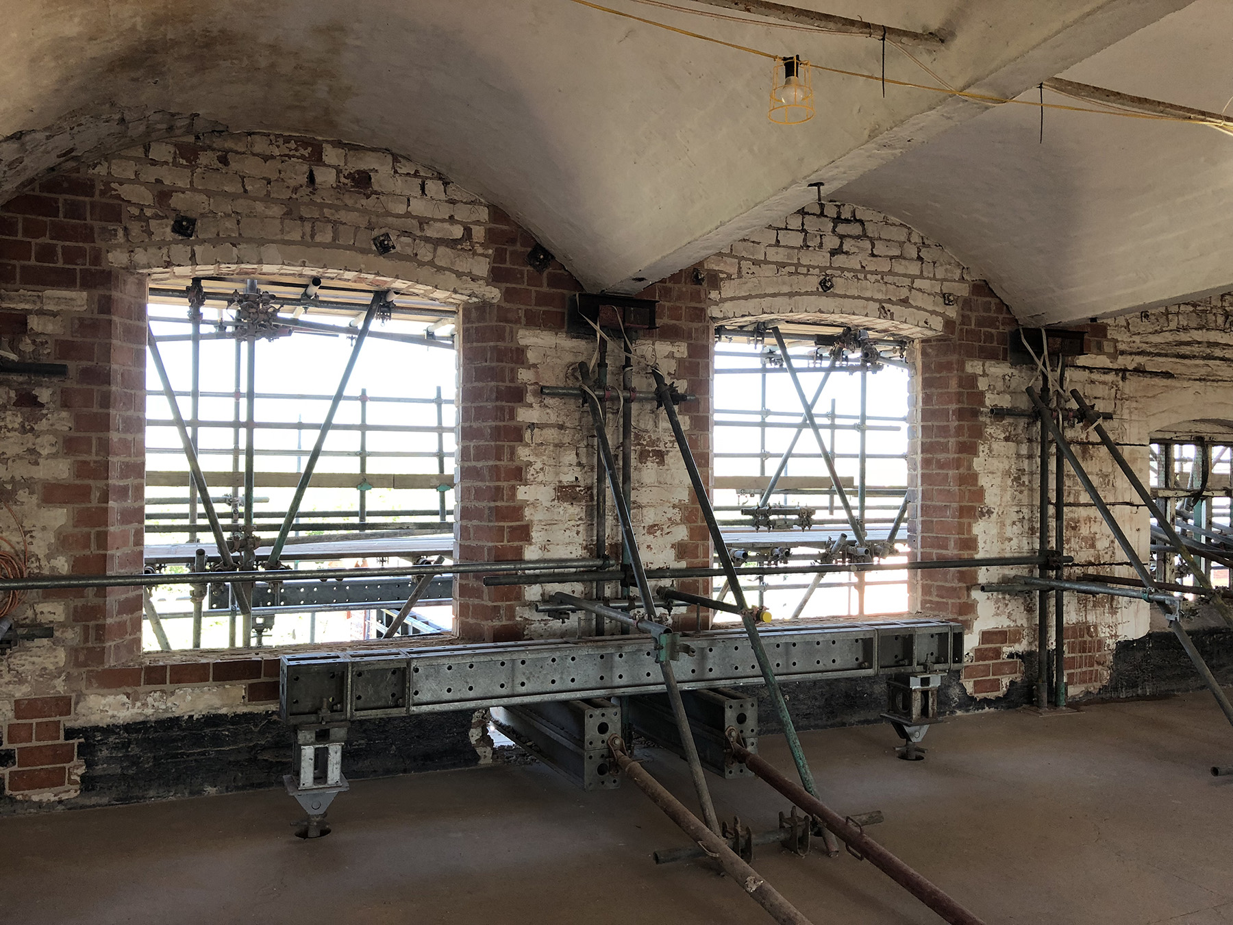
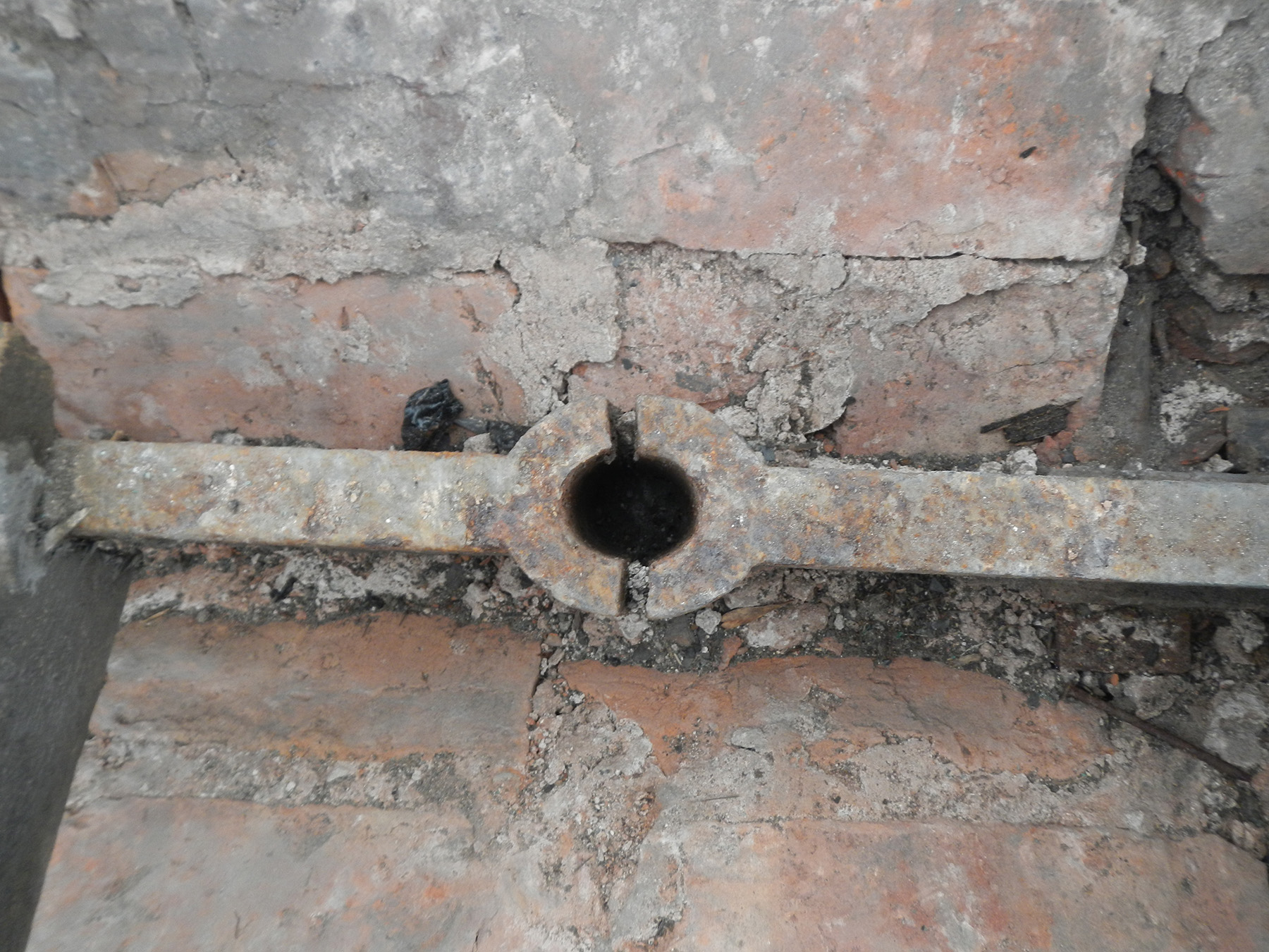
3. Decayed timber within the perimeter walls. External weathering and moisture from the wet barley germination during the maltings phase caused extensive decay, particularly around the cast-iron beam bearings. This resulted in outward bowing of the masonry, as load was diverted around the soft, rotten timber.
4. Compromised lateral stability. The connections between the floors and the cross walls at the south end of the mill had been interrupted when voids were formed during the conversion to add steeping tanks. Further damage occurred during their subsequent removal in the 1980s. This damage reduced the ability of the floors to act as diaphragms, and the floors could not adequately transfer wind and other lateral loads to the principal stability elements.
5. Potential for further movement. With the building having sat empty without heat and being subject to water ingress since the 1980s, it was generally damp and cold. As such, there was the potential for drying and temperature changes to induce movement in addition to that which could occur at the foundations as the planned refurbishment modifications were made.
Avoiding collapse
Some of the failures of the cast-iron frame were known decades ago. The Main Mill, along with many other buildings on the site constructed afterward, incorporated varying degrees of column and beam strengthening that appeared, in many instances, to have been installed with haste. Typically, this consisted of parallel flange channel sections that encapsulated the cast-iron columns, with brackets fitted to the heads of the channels to support the cracked beam ends.
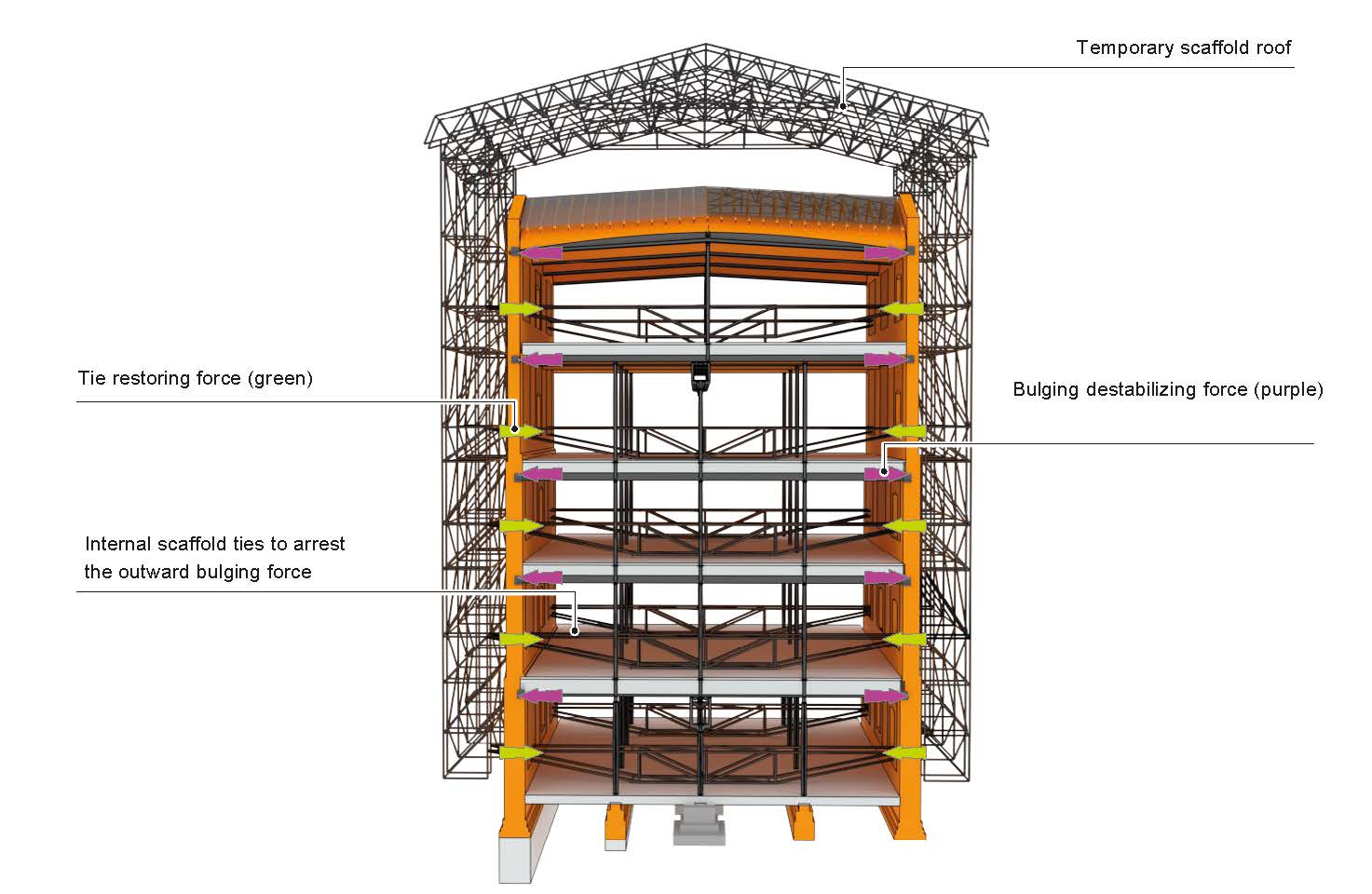
However, the elements most at risk for collapse were the bulging masonry piers. If localized collapse of the masonry had occurred, it could have led to a more progressive collapse of the cast-iron frame due to the loss of beam-end bearings.
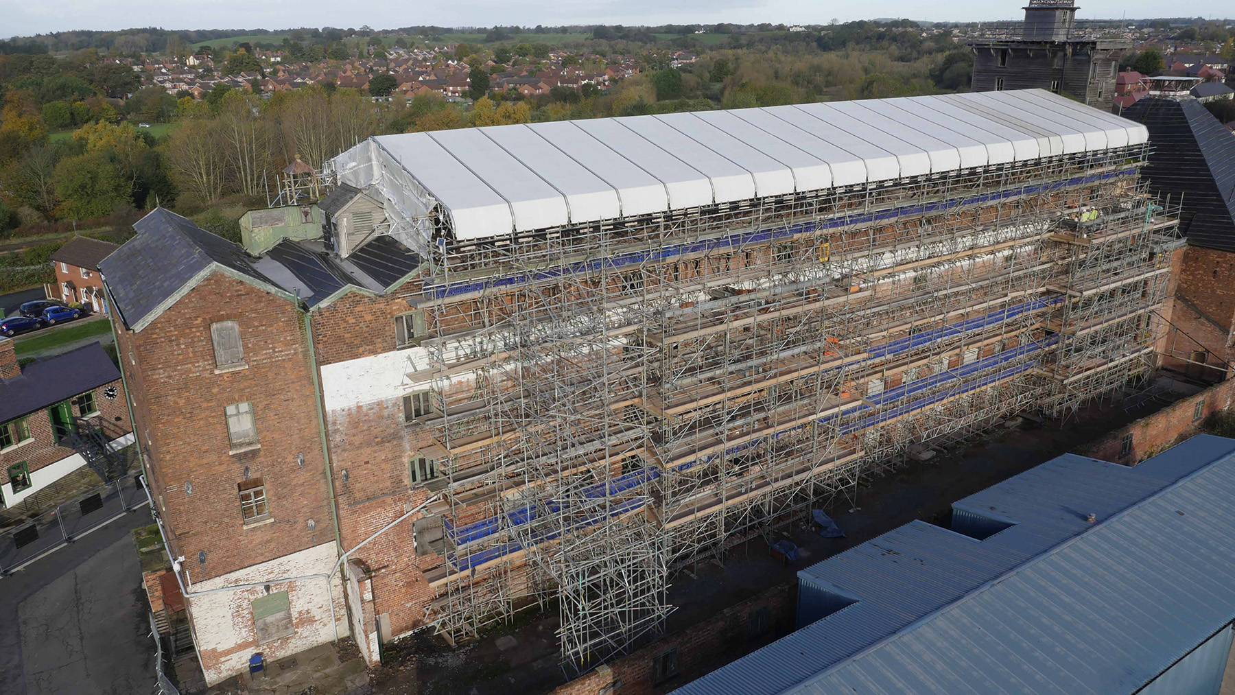
In response, the team built an extensive propping and tying scaffold with a temporary roof that engulfed the building to protect its failing integrity. The temporary roof also allowed the building to dry until viable solutions were devised to save the building.
The scaffold was dense and restricted movement around the mill because the ties reached through the full width of the building at the limited window positions. This would later bring an additional constraint to the project: The planned refurbishment and repair of the building needed several scaffold adaptations to enable access and allow phased repair of the masonry walls. Where adaptations were not possible, the new materials and other temporary works were threaded through the thousands of scaffold poles.
Responding to a unique building
In order to consider what interventions would be needed to stabilize the structure, the design team first needed to understand the existing conditions and evaluate its capacity. An assessment of the residual capacity of the cast-iron frame was performed using conventional and more intricate methods derived from techniques originally developed to assess stainless steel elements for which the stress-strain curve is nonlinear, as it is for cast iron.
In the case of the cast-iron beams, the continuous casting of the sections over the column nodes made the beams initially behave as continuous elements. However, due to the differential settlement and timber-bearing deterioration, internal beam ends were typically found cracked up to two-thirds of their total depth. This created a condition more akin to a simply supported beam. As a result, a range of fixity could exist, depending on the beam conditions, with the critical flexural position shifting from beam ends to midspans.
When it came to the columns, the ground- and first-floor columns exhibited the lowest residual factors of safety — as low as 2 to 3 — made worse by the increased self-weight introduced during the maltings phase conversion.
The masonry walls, as typical for walls built in that era, possessed ample capacity if not factoring in the presence of any degraded timber. For the perimeter walls, the main challenge was to remove and replace the decayed timber beam bearings and lintels over the windows while working within the propping and tying scaffold. The extent of timber in the exterior walls was widespread and the window masonry infills (added in the maltings conversion) had likely become unintended alternate vertical load paths.
Approach
Historic England, in collaboration with architecture firm Feilden Clegg Bradley Studios, devised a detailed proposal for the mill restoration that combined a historic, cultural offering alongside office space. In the plan, the Main Mill would be a natural focal point for the site and the first phase of a greater master plan. The adjacent kiln structure would be developed concurrently to provide vertical circulation, and together with the earlier refurbishment of the stables, this work would drive the wider regeneration of the entire site.
Future phases will include works on all other remaining historic buildings in addition to the development of new commercial and residential spaces.
Initial assessments indicated that the existing structure did not have sufficient capacity to support the level of office loading recommended in the current U.K. national standards. Based on this, the design team conducted a feasibility-level exercise for the measures that would need to be taken to bring the floors in line with the current U.K. national standards. This resulted in needing a new internal steel frame that would then deliver the capacity required to support the modern office loads and would render the existing frame essentially redundant, preserved in situ.
The design team also considered an alternative to the managed office plan, whereby the new structure would be minimized by imposing load limits throughout the managed office space.
Historic England brought extensive experience in the area of managing the use of existing buildings, and the architects were able to demonstrate that the function of the office would not be negatively impacted by loading restrictions. Under this approach the requirement for new steel framing would be minimized. Ultimately, the design team chose the second approach for the project.
The design team identified a set of principles for guidance. These principles established a structural strategy that was sympathetic to the building and its history:
1. Favor performance-based design rather than simple, deemed-to-satisfy rules to predict and assess the consequence of making the structure compliant.
2. Consider function and risk mitigation from first principles, allowing realistic loading to be adopted without compromising the final use.
3. Use targeted structural fabric surveys to better determine actual material strength and condition of critical elements and avoid large-scale, potentially damaging intrusive works.
4. Enhance resilience and provide additional load paths where possible to address progressive collapse requirements, with each intervention ideally contributing to the overall structural adequacy of the building across multiple fronts.
5. Ensure the different phases of alteration and repair are clearly visible to help tell the story of the structure and the building as a whole.
6. Consider the method of construction as an integral part of the overall design; do not wish elements into place.
Some of the specific methods the design team employed went beyond conventional conservation techniques. However, the design team possessed deep experience and knowledge, which meant any nonstandard approaches could be successfully carried out.
Enhancing resilience
Key to the overall structural scheme was the need to enhance the resilience of the existing frame. U.K. building regulations require engineers to meet a specific set of structural robustness and disproportionate collapse criteria, but these are not readily applicable to historic construction. Broadly speaking, there are three routes to robustness:
1. Implicit methods. Resilience is achieved by using vertical and horizontal ties, as defined for certain common forms of modern building construction. Cast-iron framed buildings such as the Main Mill are not covered by such guidance.
2. The use of alternative load paths. Determine alternative ways in which a structure may be able to support a load in the event an element is compromised.
3. Design as key elements. In the event that an alternative load path is not identified, can the capacity of an element be enhanced to resist the hazard to which it may be subjected? This is generally the last option to be adopted since it only reduces the likelihood of an element failure.
The load-bearing structure of the Main Mill comprises masonry and the cast-iron columns, which were weak in tension. Furthermore, the simple socket joints between columns and beams did not possess tensile capacity. Vertical tying could not be achieved without impacting the heritage aspects of the building.
Saving these historical features required that the robustness and resistance to disproportionate collapse be attained through a combination of ensuring an alternative load path and key element design.
Cast-iron columns
To address the overstressed cast-iron columns, the design team proposed a new steel frame specific to the ground and first floors. This frame would also provide one floor level with the capacity to fully comply with modern loading requirements.
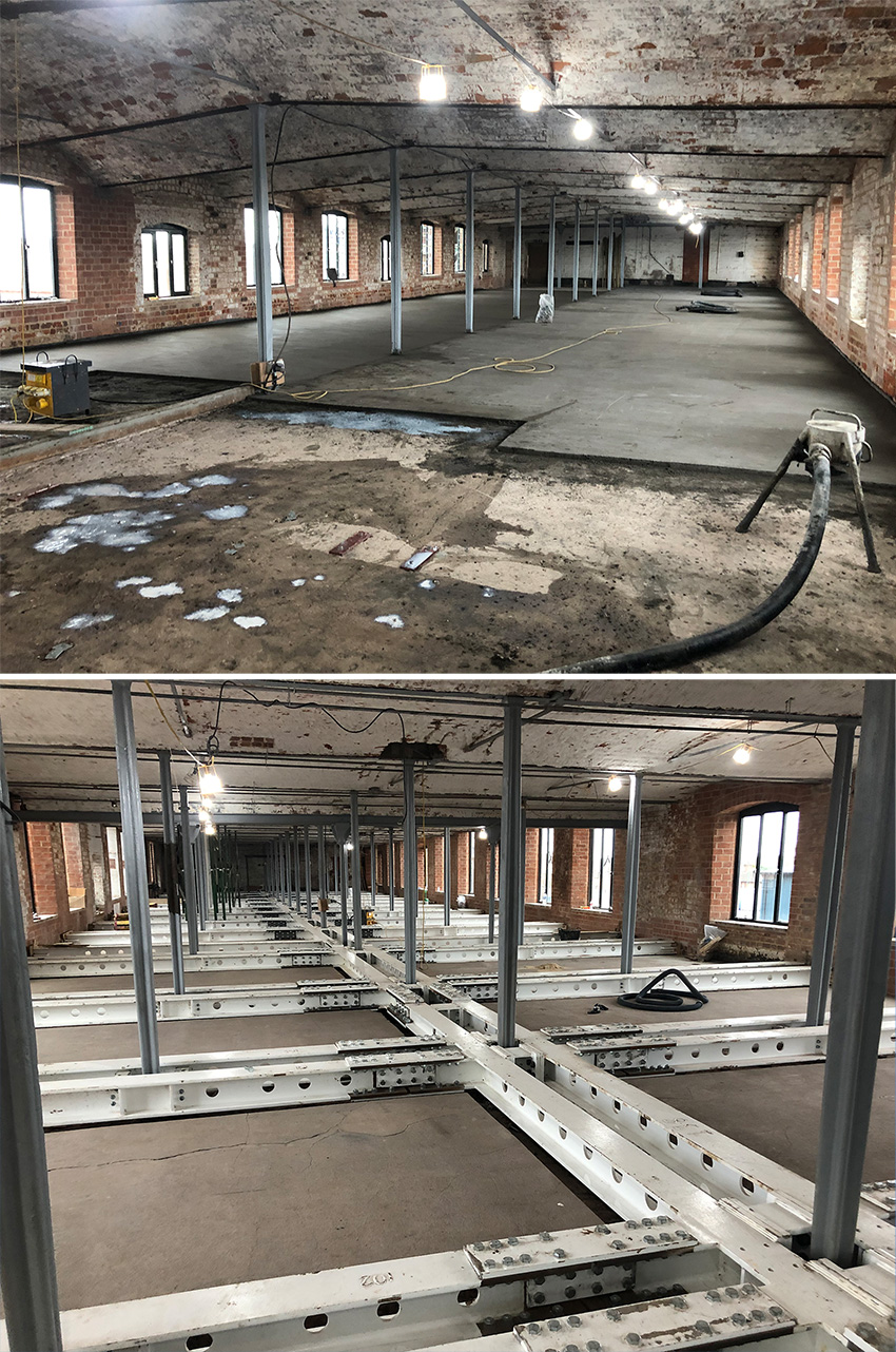
At the first-floor level, the frame comprises a grillage of steel beams that are recessed into trenches cut into the overburden of the jack arch floors to avoid compromising headroom. The grillage is supported by the perimeter masonry walls and a small number of central columns are supported on new pad foundations. The grillage at the first floor in turn supports paired columns at each central cast-iron position, which alleviates a component of load acting on the second floor.
Furthermore, the grillage was designed to support all new activity at the first-floor level, thereby reducing load on the existing cast-iron ground floor columns and alleviating live loading from the second floor on the central cast-iron first-floor columns via new columns placed at the second-floor beam ends.
In addition, the grillage acts as a safeguard for the overstressed columns on the ground floor, with the frame being designed to “catch” and support the column load in an accidental load condition, and the grillage also acts as a safeguard for the cracked beams within the first-floor structure, with ties hooked around the beam ends and supported off the grillage to create an alternative load path.
Further up the building, the factor of safety in the existing columns rises to more acceptable levels. Provided alternative load paths could be established to span around potential localized defects, no further structural intervention was required.
Cast-iron beams
Fabric investigations showed that a significant number of the cast-iron beam ends had cracked. Other beams were also at risk of cracking due to the refurbishment works and the potential for future building movement. In the Main Mill it was observed that the cracks did not pass through the full section.
In general, the remaining connected section was sufficient to transfer the necessary beam shear force to the columns. However, an alternative load path was still required to satisfy structural robustness and disproportionate collapse criteria.
To ensure the optimal load path and meet collapse criteria standards, the first-floor cast-iron beams were equipped with steel hangers supported from the steel grillage. The second- to fourth-floor jack arch floors were modified to increase their capacity to arch in two directions, bypassing the cast-iron beams in an accidental scenario in which the integrity of the beams was lost.
To achieve this, the team took multiple steps. Across the building, new steel tie rods were installed that can resist the horizontal thrust that would be established should arching occur.
Work crews placed a new, bonded, fiber-reinforced structural screed throughout the floor plates, replacing the original cracked and worn screed to enhance the ability of the floors to redistribute loads. Steel hangers were added at beam ends to catch and lift the arch reaction should a beam crack fully. And finally, the design team added resin-fixed shear rods along the length of the cast-iron beams to enable load to be lifted to the level at which arching could occur.
The screed was designed to work with the other elements to ensure load redistribution and redundancy while also enhancing diaphragm action.
Floor diaphragm
In addition to the modifications outlined earlier, it was necessary to reinstate the diaphragm action that had been lost as a result of the maltings alterations. The team achieved this by infilling the old steeping tank voids using reinforced concrete placed on metal decking. This configuration reestablished the load paths between the floors and the cross walls to achieve lateral stability. Second, the team placed strapping at the interfaces between the floors and cross walls to enhance load transfer, providing tension ties to increase shear friction and act as lateral ties for robustness.
External masonry walls
Given the extent of decay that was present, work crews removed all the timber embedded within the perimeter walls. The vertical loads in the walls were being transmitted around the compromised beam bearings into the infilled windows. With these infills now needing to be removed to reinstate the original flax mill arrangement, the design team developed a carefully choreographed 13-step sequence to safely remove the timber and complete subsequent repair of the walls.
Given the intricacy of the sequence, the design team proposed a limited trial works on one bay to validate and fine-tune the approach. The works required a separate masonry needle frame to be threaded around the existing temporary propping scaffold that supported the structure.
All components for this needle frame had to be light enough so that they could be manually lifted into position. The frame required separate foundations, and the process was further complicated by varying ground conditions on either side of the building. Pad foundations on one side and temporary screw piles on the other side coordinated around the archaeology.
The area of bricks removed and reinstated around the bearings and lintels was minimized as a result of this carefully planned sequence. New concrete-bearing pads and precast-concrete lintels replaced the decayed timber elements, providing the most durable long-term solution. New masonry reveals were constructed to repair the damage done during the maltings conversion.
Bricks reclaimed from the deconstruction of the infills were used for repair where possible, but there was still the need for bespoke, handmade bricks to be sourced to suit the larger-than-standard great-brick dimensions.
The completion of the Main Mill could not have come at a better time. The world is viewing the construction industry through the lenses of climate change and decarbonization. Building reuse and adaptation will be vital for these initiatives to succeed.
Although the path to saving this icon of the Industrial Revolution was long and challenging, through the efforts of the entire team, it has been possible to extend its life into a third century, and this should act as inspiration to developers, architects, and engineers alike.
As the engineers for this restoration project, it has been our pleasure to be part of the team that has secured the Main Mill’s future.
Christopher Blust, P.Eng, CEng, MIStructE, is a design director, David Watson, CEng, MIStructE, is a technical director, and Charlotte Robinson is a design engineer for AKT II in London and Manchester, England.
Project credits
Client-owner and project manager: Historic England, Swindon, England
Architect: Feilden Clegg Bradley Studios, Bath, England
Civil and structural engineer: AKT II, London and Manchester, England, offices
Mechanical engineer: E3 Consulting Engineers, Bristol, England
Landscape consultant: LT Studio, Bath, England
Cost consultant: Gleeds, Birmingham, England
Contractor: Croft Building & Conservation, Cannock, England
This article first appeared in the July/August 2023 print issue of Civil Engineering as “A Building of Innovation and Experimentation.”