By Nathan C. Roy, P.E., Kaitlyn M. Palmer, S.E., and William A. Miller, P.E.
Architecture and engineering firm Skidmore, Owings & Merrill partnered with structural engineering firm LeMessurier to design and execute Wellesley College’s dream for its new Science Complex — all while preserving a core piece of its history.
Preservation is as important as building for the future.
In October 2022, Wellesley College in Massachusetts opened its newly renovated and expanded Science Complex. Its design and construction delicately balance protecting treasured spaces on campus with meeting the needs for student learning, research, and growth. Designed by architecture and engineering firm SOM, the Science Complex is a living laboratory with strong connections to the surrounding landscape and the other structures that constitute the college’s Science Hill.
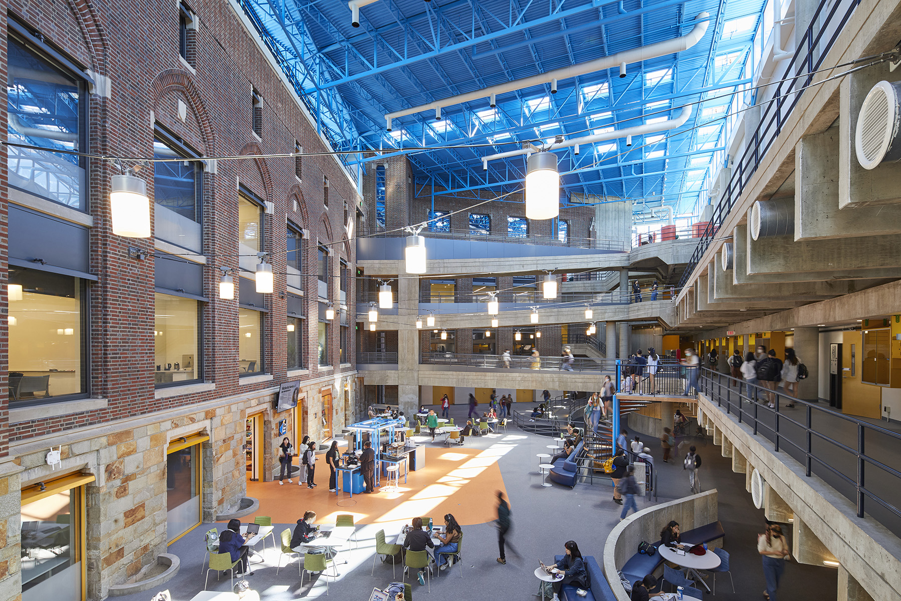
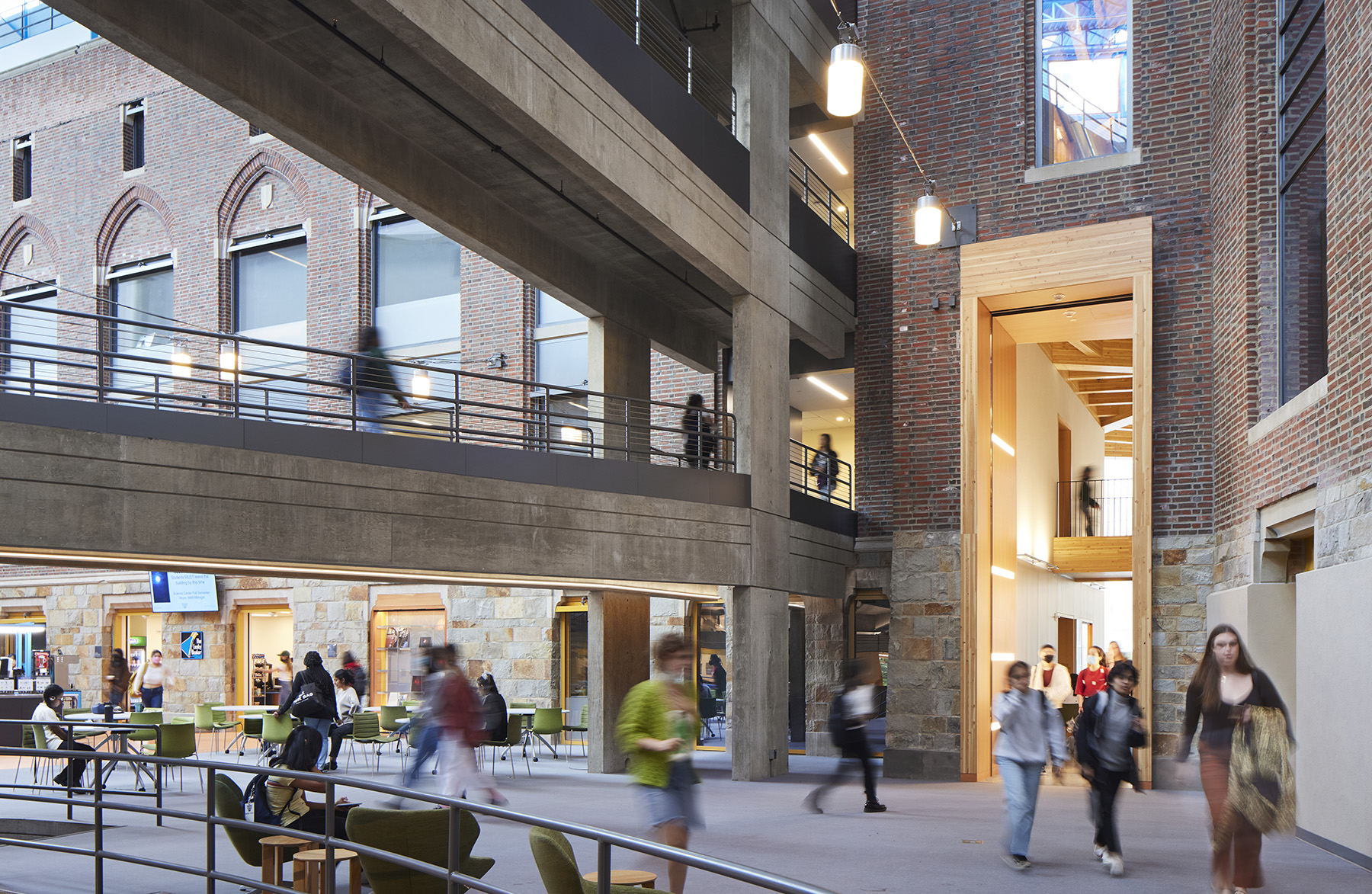
At the heart of the existing Science Complex is the Farroll Focus, a 160 ft wide by 64 ft tall atrium. Preserving it was crucial to maintaining this connection between science and a welcoming environment. However, to do that, the design team would need to save the atrium’s load-bearing brick wall dating to 1931 while demolishing the remainder of the existing structure to allow for construction of the new complex.
A history: Wellesley Science Complex
Wellesley College is a private liberal arts college for women. It was founded in 1870 and spreads across a 500-acre suburban campus designed primarily by Frederick Law Olmsted Jr. Since its founding, the college has maintained that there is a “critical importance” for women to be educated in the sciences. Today, the school says, among liberal arts institutions, it educates the highest numbers of female students who go on to earn Ph.D.s in STEM (science, technology, engineering, and math) fields. All these STEM classes are housed in the Science Complex.
The complex comprised several buildings constructed and expanded in four phases between the early 1920s and early 1990s. The Margaret C. Ferguson Greenhouses, built in 1922, were the first.
The greenhouses were followed by Sage Hall, a four-story Gothic building designed by Day & Klauder Architects that was completed in 1931. The building, with its brick load-bearing masonry walls, comprised two wings in a pointed arc plane extending from a central tower.
By the 1970s, Wellesley had decided to integrate the sciences into a single location on campus. Consequently, the college turned to architectural firm Perry Dean and Stewart to design an addition known as the Lab Wing. Situated to the south of Sage Hall, the late modern six-story L-wing has flexible and open spaces for teaching and research as well as a two-story library overlooking the campus. The exposed-concrete structure with its glass facade was arranged so the functions of the spaces within the building could be seen from the exterior.
Steel trusses from the 1970s construction spanned between the L-wing and Sage Hall to create an extra-ordinary indoor space between the buildings: the Focus, which is one of the first atria in a science complex, according to the college’s website. The Focus originally housed the administrative functions of the Science Complex but was later converted to an open space for community use.
The atrium is enclosed by Sage Hall’s masonry facade to the north and east, the L-wing to the south, and a glass wall to the west. Seven exposed-concrete walkways span the atrium at the second, third, and penthouse floors to connect the L-wing to Sage Hall at the east and west ends, helping bring scale to the space. The centrally located atrium is accentuated by the brick facade of Sage Hall; colorful, postmodern steel roof trusses; and the exposed concrete of the L-wing, creating a unique space that is a campus favorite for gathering, studying, and collaborating.
In the early 1990s, Wellesley asked Perry Dean Rogers and Partners, which had done the aforementioned design work in the 1970s under the name Perry Dean and Stewart, to design the East Wing addition to house the physics and computer science departments. The E-wing mimics the architecture of the L-wing and complements the Focus with a smaller atrium reaching to the east side of Sage Hall.
Renovation and expansion
The expansion project included renovating the L- and E-wings, which involved modernizing laboratory, vivarium, aquatic, and research spaces. While the L- and E-wings could be saved, the design team and Wellesley concluded that Sage Hall could not accommodate a modern laboratory and teaching program. This was primarily due to the limited floor-to-floor height in the existing structure. To make way for a new addition, the existing Sage Hall would have to be demolished while its facade and the Focus would be preserved.
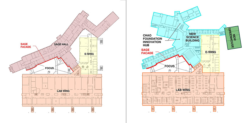
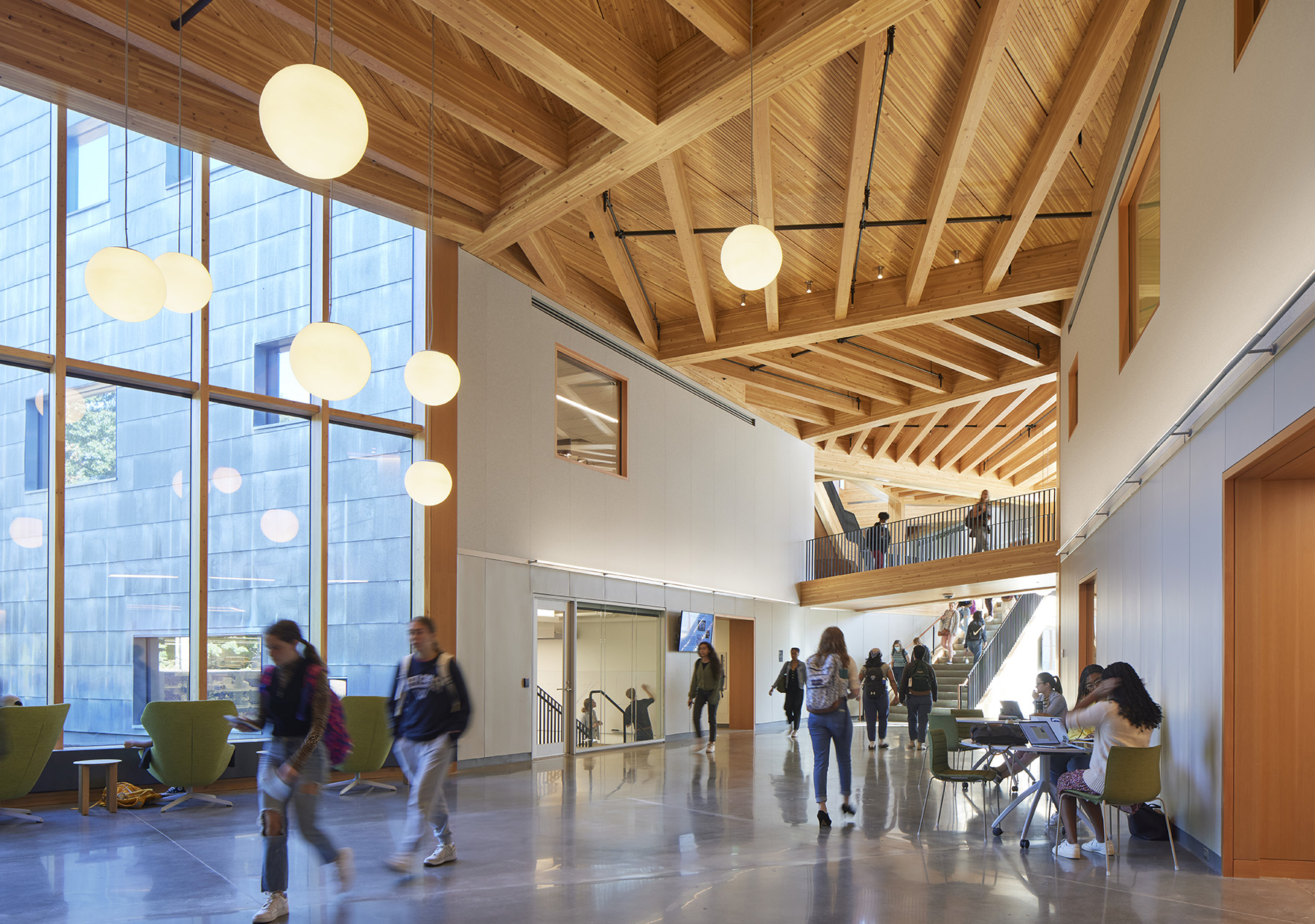
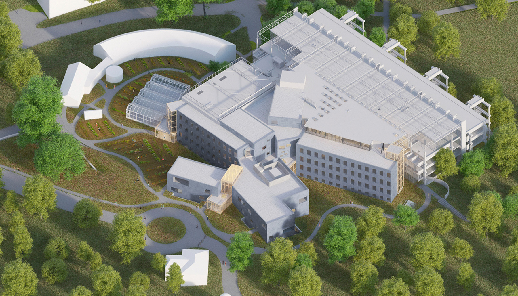
The new four-story, four-wing, 97,000 sq ft addition comprises offices, meeting areas, an auditorium, and core research spaces. This includes the Chao Foundation Innovation Hub, one of the addition’s defining features, which is a cluster of interdisciplinary teaching labs that offer space for instructors to explore new teaching techniques and put scientific research on display.
The four wings of the addition are situated around the Hub, which connects to the existing Focus atrium and serves as a place for interdisciplinary collaboration.
The Data Lab is home to data-driven research, and the Frost Center for the Environment is home to sustainability, ecology, and environmental studies. The Frost Center also includes new teaching and research greenhouses, gardens, and the Global Flora Conservatory.
The 56 ft tall addition, which is at the site of the original Sage Hall, was built over an existing steam tunnel, which is part of the 1931 construction connecting the Science Complex to a power plant. Complicating construction of the addition, the utilities and steam tunnel needed to remain operational during demolition and construction.
Columns and footings were strategically located so as not to impose additional loads on the tunnel. The design team placed mini-pile deep foundations at select spots adjacent to the tunnel and basement walls of the L- and E-wings to limit impact from the new construction.
The four wings are typically structured of composite slab on metal decking supporting composite steel framing. Steel-braced and moment frames provide lateral stability. In the final condition, the addition’s floor slabs are attached to the existing masonry Sage Hall facade wall to provide lateral support while detailed to allow relative vertical movement between the structure and facade wall.
The Hub is built out of mass timber. Laminated timber decking with exposed-concrete topping is supported by a warm wood structure of intertwined glulam beams and girders at varying angles. Timber mullions are used at the curtain wall in the Hub and at entry vestibules.
Constructed at a fast pace, the Hub has a lighter carbon footprint with no additional fireproofing. The design team realized cost savings on fit-out finishes since the wood structure has been left exposed.
Saving Sage Hall’s facade
For a facadectomy, the facade of a building is retained and preserved while the rest of the building is demolished to allow for new construction. In the final condition, the original facade is supported by the new building — a function that is the responsibility of the design team and engineer of record. The temporary condition to allow demolition and construction of a new building is typically part of the contractor’s means and methods and is the responsibility of the contractor and its designated representative.
The design of a temporary bracing system for facade preservation requires careful coordination throughout the life cycle of the construction project, including an initial assessment of the existing structure, demolition activities, construction of the new building, and the final building structure.
With the approval of Wellesley College, Turner Construction Co., which served as the construction manager, engaged LeMessurier to also provide contractor support services for design of the temporary bracing of the facade wall.
While not common, LeMessurier as the engineer of record was brought on to assist in this design due to its understanding of the existing and new structures. Because of the dual roles as the engineer of record and contractor’s engineer, it was important to clearly define which support services of the contractor’s means and methods LeMessurier was being engaged to design.
Early in the design process, LeMessurier, SOM, and Turner identified constraints on the temporary wall bracing system. LeMessurier and Turner examined the budget, geometric limitations, demolition procedures, and construction sequencing so the team could make informed decisions to determine the appropriate bracing system.
Wellesley, Turner, and LeMessurier conducted an initial site walk-through that allowed each one to voice concerns. The design team performed a condition assessment of the building with select exploratory demolition to better evaluate the existing building structure.
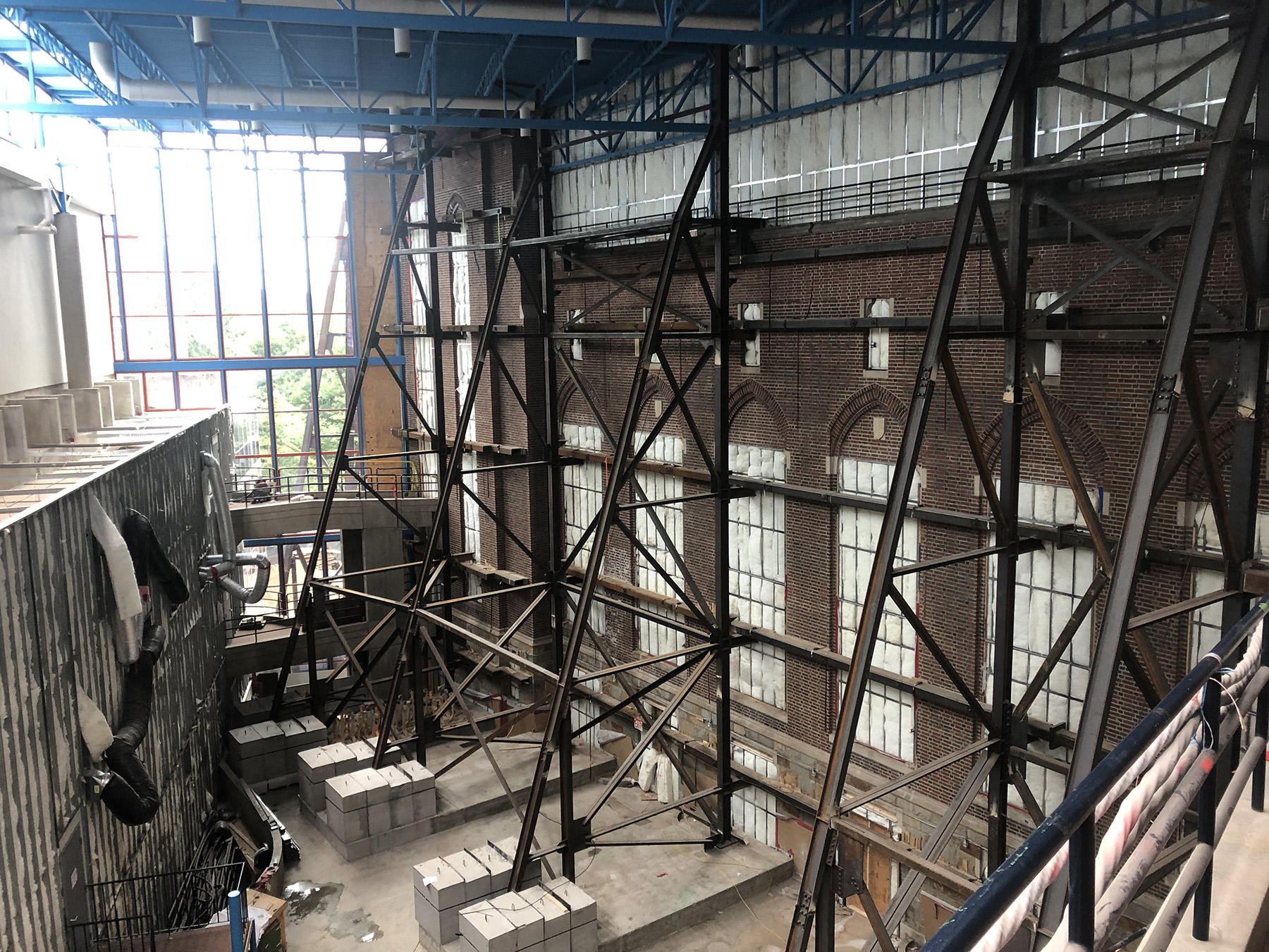
A 3D scan of the Focus helped better define the geometry and limitations on the temporary bracing system. Multiple bracing systems were investigated, including struts across the atrium to the L-wing structure; deep, wide-flange vertical strong backs with kickers; and trussed frames.
The critical constraint on the temporary system was erection limitations within the Focus. Typically, temporary bracing for facadectomies is outside the existing building footprint; however, the original exterior wall of Sage Hall was now an interior atrium space limited by the roof over the Focus atrium, the L-wing structure, and seven pedestrian walkways crossing the atrium.
The temporary bracing could not be within existing Sage Hall due to the proximity of the existing below-grade tunnel. The team determined that the best solution was a trussed frame that could be erected with multiple smaller sections.
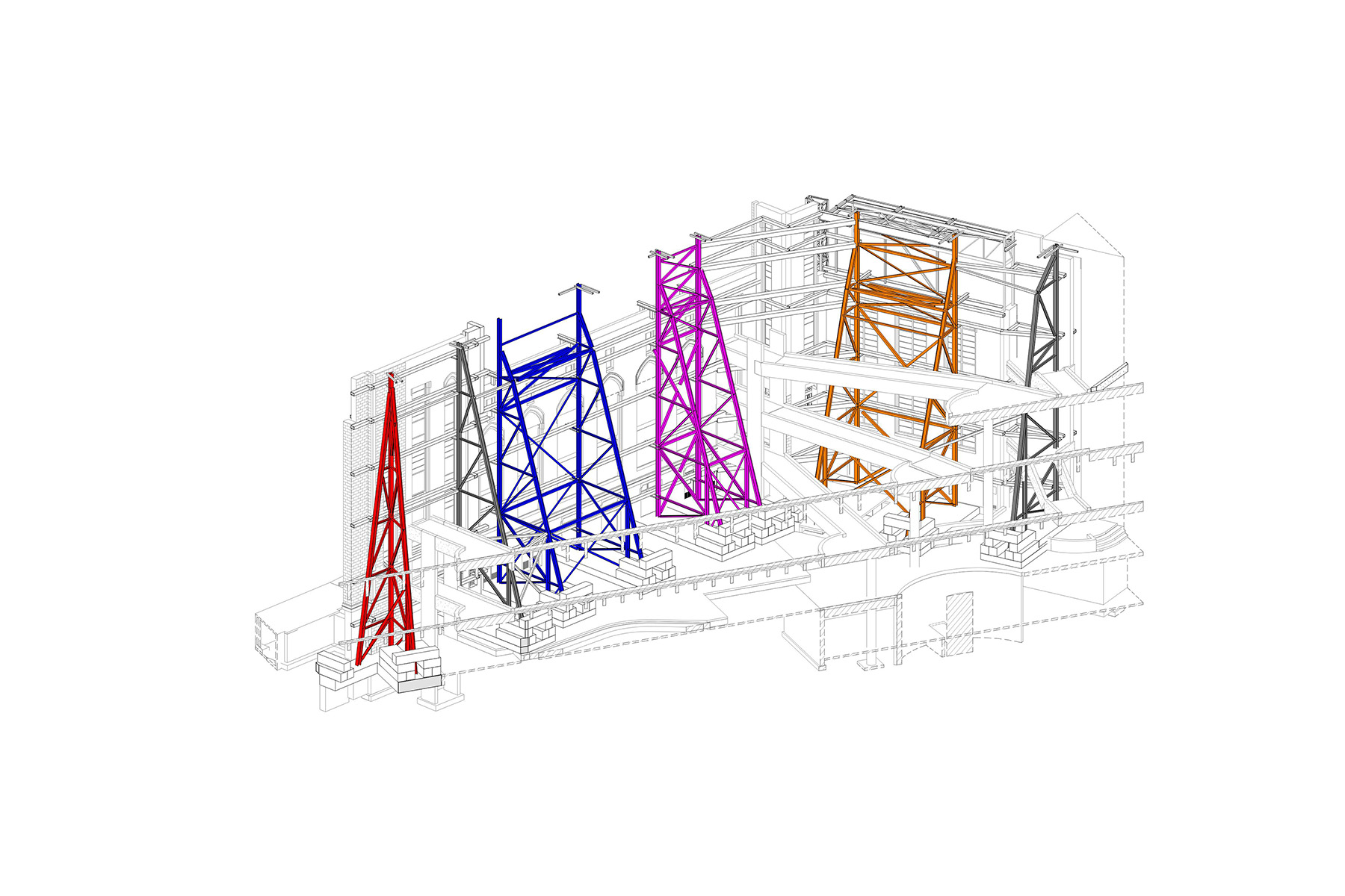
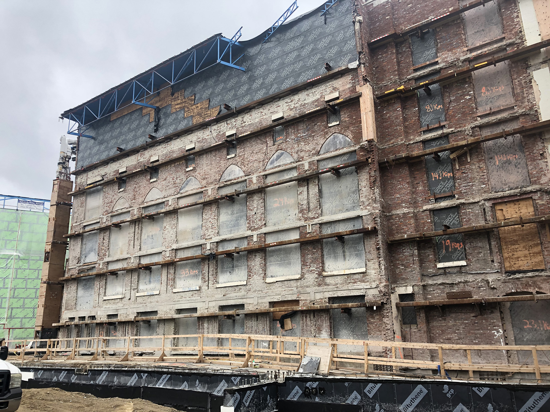
Ten trussed frames were inserted along the Sage Hall facade wall to provide lateral support during demolition and construction. The trusses cantilevered up 65 ft from the Focus floor and were limited to widths of 20 ft at their bases. To simplify erection, the trusses were configured with W10 chord members and double-angle diagonals with bolted connections.
In addition, the trusses were laterally attached to the Focus roof as the 1970s construction included an expansion joint between the Focus and L-wing roof. Therefore, the Focus roof relied on Sage Hall for lateral stability.
The trussed frames were supported by an 18 in. thick footing. This footing extended 4 ft down the facade wall to accommodate the excavation and installation of new footings within the addition without surcharging the existing Sage Hall foundation wall, which supports the Sage Hall facade.
Critical to the design was providing sufficient weight to prevent overturning. Concrete ballast blocks were placed at the truss ends away from the Sage Hall wall, and the truss foundation was anchored to the Sage Hall foundation wall to use the weight of the existing facade wall to anchor the truss.
Typical of construction in the 1930s, the existing Sage Hall facade wall was a load-bearing structure with three-wythe brick masonry. In the original construction, it acted as a shear wall to provide stability along its length. The wall was braced perpendicular to its length by the floor structure and perpendicular walls along the building length.
For the temporary bracing system, no positive attachment anchorage was permitted on the exposed Focus side of the facade wall. Hollow structural steel walers on the inside and outside faces of the masonry wall provided lateral support, spanning approximately 24 ft.
Outriggers at existing windows cantilevered from the trussed wall bracing. Walers and outriggers were situated so as not to interfere with the existing building structure or the structural framing for the new building. The trussed-braced frames were configured in pairs for stability perpendicular to the frame during erection. Four paired-trussed frames were used. These bracing framers were self-stable during erection with cross bracing between them.
Pairs of trussed frames were braced together with horizontal angles. Because steel erection occurred indoors and all equipment and material needed to fit through a 6 ft by 8 ft door opening, work crews used an all-electric, zero-emission crane.
Frames and footings were detailed so the end 6 ft of the trusses and 10 ft of the footings could be left out to accommodate crane movement and steel erection. Portions were completed as construction backed out of the atrium.
Each trussed frame location required special coordination in relation to the existing structure. The footings were designed to span the existing duct banks below the floor while other trusses were built over the L-wing basement, which required shoring of the level 1 slab.
Overcoming hurdles
One of the most challenging aspects of the site was the bracing adjacent to five of the seven pedestrian walkways at the east end of the atrium. Two trussed frames were configured to extend under three walkways while a third frame was configured around two of the walkways.
The design team coordinated operations with the demolition contractor and its engineer to minimize the impact of demolition activities on the remaining portion of the facade wall. The existing building’s floors were fully shored along the facade wall.
After shoring installation, work crews saw-cut slabs and beams to separate the building to be demolished from the wall that was saved. An instrumentation program comprising real-time vibration monitoring in the L-wing, inclinometers, displacement gauges, crack meters, and levels was installed to evaluate performance and movement during demolition and construction of the new buildings. With set threshold limits, the instrumentation system sent alerts to the design and construction teams.
Portions of the Focus roof extended over the Sage Hall facade wall to be preserved and were supported by the setback building structure of Sage Hall that was removed. Temporary removal of these roof sections was not possible due to critical utilities located on the roof that served the L- and E-wings that needed to remain in operation during construction.
Trusses and steel framing in these areas were configured to laterally support the facade wall and vertically shore the roof and utilities. In the final condition, these portions of the existing roof structure are supported by the new addition.
Another challenging aspect of the temporary work was providing support for mechanical piping extending vertically from the roof to the below-grade tunnel, which, as mentioned earlier, needed to remain operational throughout construction.
Utilities were more than 8 ft from the Sage Hall facade wall, placing them well within the limit of demolition and new construction. Clearance within the shaft and around utilities was minimal, so the size of the shoring system was critical. Vertical steel angles were placed in the four corners of the shaft with half-inch plates used for diagonal bracing between them. The trussed shaft was braced to the facade-bracing system over its height. Utilities were attached to the trussed frame with demolition and construction around the trussed shaft.
Thanks to the collaborative, goal-first approach to this project, Wellesley College will have the modern, future-forward facility and resources it needs to continue educating women in STEM fields for decades to come.
Nathan C. Roy, P.E., and Kaitlyn M. Palmer, S.E., are principals for LeMessurier in Boston. William A. Miller, P.E., formerly with LeMessurier, is now with HGA in Boston.
Project credits
Architect: Skidmore, Owings & Merrill, New York City
Structural engineer: LeMessurier, Boston
Geotechnical engineer: Haley & Aldrich, Boston
Contractor: Turner Construction Co., Boston
Steel fabricator: Canatal Industries Inc., Thetford Mines, Quebec
Steel erector: MAS Building and Bridge Inc., Norfolk, Massachusetts
This article first appeared in the July/August 2023 print issue of Civil Engineering as “Saving the Wall.”