
By Paul Mostella, P.E., S.E., M.ASCE
3D photogrammetry captures images to create digital twins of electric utility infrastructure. The technology allows engineers to evaluate equipment and plan repairs with greater accuracy, fewer outages, and less risk to personnel.
ASCE’s 2025 Report Card for America’s Infrastructure gave the nation’s infrastructure an overall grade of C. While this is the highest grade ever reported in the quadrennial assessment, grades for individual categories ranged from B to D. The energy/utility industry scored a D+ this year, compared to a C- in 2021. Of the several key trends identified in the report, one stated: “Aging infrastructure systems are increasingly vulnerable to natural disasters and extreme weather events, creating unexpected and often avoidable risks to public safety and the economy.”
Technological advancements help civil engineers assess the state of our aging infrastructure and devise repairs and replacements that will create more reliable and resilient infrastructure. Among these advancements is the 3D photogrammetry survey, which offers a transformative approach to capturing and preserving records. This surveying technology, which creates accurate 3D models from photographs, has revolutionized various industries by providing detailed and precise data with the added benefit of digital preservation of records for future comparisons.
With aging electric utility infrastructure comes aging and outdated records. Often, historical records are unavailable or illegible because of poor scanning technologies at the time, document mishandling, or documents simply being misfiled or lost. In many cases, electric utility engineers must act as detectives, exploring and piecing together inadequate records. A missing drawing list here and a design note there can lead to a lengthy search through a wasteland of data; 3D photogrammetry can breathe new life into this process.
How it works
At its core, 3D photogrammetry involves taking multiple high-resolution photographs of an object or scene from different angles, similar to shooting a movie. The process begins by collecting overlapping images. The more images captured, the more detailed and truer to life the resulting model will be. Advanced software detects common reference points in the images and uses them to calculate precise 3D coordinates and measurements to create a 3D model.
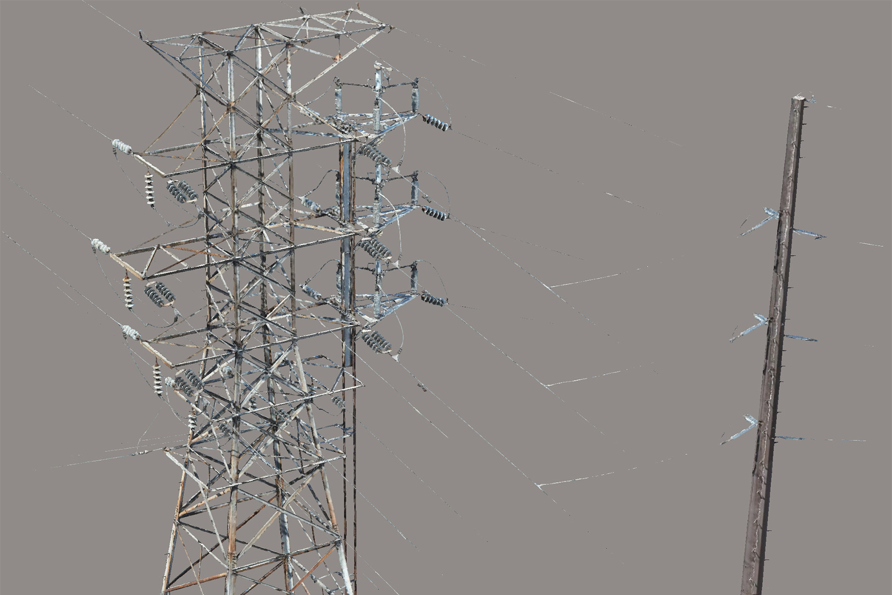
The resulting model, known as a digital twin, maps the data to the physical world and allows engineers to revisit the surveys to question, confirm, plan, and execute with confidence. In the electric utility space, the application of 3D photogrammetry ranges from structural condition assessment to corrosion mapping, equipment evaluation, and electrical clearance verification. This technology enables:
- Structural engineers to model, evaluate, and remediate structures.
- Engineering and surveying teams to identify missing or damaged members.
- Corrosion experts to map and visually quantify corrosion issues.
- Electrical engineers to ensure electrical equipment is functional.
- Transmission and station engineers to verify electrical clearances per the National Electrical Safety Code (NESC) for existing or new installations.
- Construction crews to measure ingress and egress locations to limit disturbances to the land and the environment.
Outside the electric utility industry, 3D photogrammetry can be used for various purposes, including architectural reconstruction, heritage preservation, precision farming, environmental monitoring, and forensic investigation.
An array of benefits
3D photogrammetry offers many benefits over other data-capture methods. For one, 3D photogrammetry provides highly accurate and detailed records. Structural members and the geometries of their connections can be measured using a digital twin model that was generated by 3D photogrammetry. In the absence of existing records, these measurements become the basis of new detailed records; their values become design inputs. These inputs are crucial when the engineer of record calculates the existing capacity of the structures supporting the utility infrastructure.
This survey technology captures data without physical contact, making it noninvasive and ideal for fragile, precarious, or hard-to-reach objects and sites.
Climbing systems — such as ladders, platforms, and step bolts — attached to utility infrastructure are also aging, so their original maximum intended loads are reduced. Safety standards have been updated to require the evaluation of climbing systems before repairs begin. For example, a 2017 revision to Occupational Safety and Health Administration Standard Number 1910.24 for step bolts requires that engineers ensure that “(e)ach step bolt installed before January 17, 2017, is capable of supporting its maximum intended load.”
Additionally, there are often physical or electrical constraints to traditional surveying methods. For example, sometimes the utility cannot take a piece of equipment out of service to accommodate a physical survey. In cases like these, a 3D photogrammetry survey taken by unmanned aerial systems, or UASs, provides a noninvasive solution that mitigates the need for climbing systems; avoids introducing a hazard to utility workers; and acquires equivalent, if not better, survey information and observational data — without an outage.
Another benefit is efficiency. The process of capturing and processing photogrammetry images is relatively quick, allowing for the timely creation of records. As computing power continues to increase, this efficiency will constantly improve.
What’s more, the digital records created can be stored and accessed easily, ensuring long-term preservation and accessibility.
3D photogrammetry is versatile and can be applied across various fields. For example, in the utility industry, 3D photogrammetry surveys can be used by operations and maintenance teams to identify part numbers of hardware attached to a structure, assess grounding conditions at a site, and document the presence of adjacent aboveground utilities in case maintenance work needs to be performed in the future.
Finally, 3D photogrammetry gives an engineer the ability to visually identify corrosion on an object. The engineer can see bolts and structural members that were once strong and steadfast but now bear the scars of time. Furthermore, UASs can access spots that typically would not be revealed from the ground, such as the top of a structure or a piece of utility equipment.
Using the digital survey data, experts can assess and classify the areas of corrosion. These corrosion classifications are combined with mapping to guide the engineering team in creating a remediation plan to address the corrosion.
Comparing options
Of course, 3D photogrammetry is not the only solution in the industry. There is also laser scanning, which is a noninvasive method that offers unique advantages and disadvantages. Per manufacturer instructions, laser scanning equipment is typically calibrated by distance from the object being measured, and the method is highly accurate. However, errors from the equipment or the distance from the object can occur and can compound one another. This can be improved by using survey or ground controls as fixed reference points.
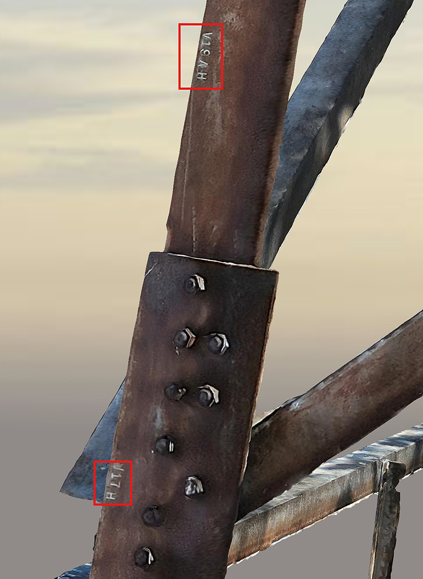
The end results of laser scans will be delivered as a point cloud, requiring engineering judgment and interpretation to decipher the information. Meanwhile, 3D photogrammetric surveys capture not only geometries, but piece marks as well.
Both methods offer benefits over traditional survey techniques, in which surveyors climb structures to collect measurements by hand. In the case of transmission lines, especially those involving lattice towers, the intricacies and details of each member that will have to be measured by hand and mapped to develop a structural model introduce many handoff points where errors may occur.
Handoff points can include the specifications that pinpoint the locations from which to take measurements, the required tools to take the measurements, the instructions for how to document the surveyed data, and the office work required to transfer field data to drawings. Each of these handoff points requires the judgment of field personnel, surveyors, and engineers.
Moreover, this method requires an electrical outage, endangers workers who must climb the structures, and may require remobilization costs if measurements are missed.
The challenges of accuracy
The accuracy of 3D photogrammetry is influenced by factors such as image quality and camera resolution. The American Society for Photogrammetry and Remote Sensing provides accuracy standards in its Accuracy Standards for Digital Geospatial Data. Engineers can rely on these standards when specifying 3D photogrammetry as a survey method. Given sufficient data capture, accuracies can be as little as an eighth of an inch on a structure with a survey volume of 100 ft by 100 ft by 100 ft. When sufficient data can be captured, with images collected from every angle, UASs are the most accurate way to create a model.
To further improve the accuracy, various strategies can be used:
- Optimize camera settings. Ensure that the camera settings are correctly configured for the scene to capture data in good lighting conditions and improve image quality.
- Plan image capture. Carefully plan the timing and location of image capturing to avoid adverse weather conditions and ensure adequate lighting.
- Use ground control points. Incorporate ground control points in the scene to provide a constant point of truth for camera alignment and calibration.
- Mix methods. Combine photogrammetry with other techniques, such as lidar, to provide more comprehensive and accurate data.
- Clean and refine data. Remove “noise” and artifacts from the images during post-processing. This can be done by an imaging professional or possibly by an artificial intelligence system.
- Use advanced algorithms. Advanced feature detection and matching algorithms can improve the accuracy of point correspondences.
- Use high-performance hardware. Invest in high-performance computer hardware to handle the computational demands of photogrammetry.
Examples from the field
To test the limits of 3D photogrammetry in the electric utility field, engineers and surveyors mapped the geometries of an electrical utility in Kentucky that had insufficient drawings. The project called for replacing aging, corroded switch equipment supported by a lattice tower. The limited information regarding the existing structure did not include connection details, member sizes, or the existing switch components attached to the lattice tower.
The surveying firm chosen for this project collected high-resolution imagery of the foundations and structure using UASs and field inspections to develop a structural model for an engineering analysis. The imagery was collected with drones in accordance with Federal Aviation Administration regulations.
Surveyors collected more than 2,100 images to develop the digital twin using 3D photogrammetry techniques. The captured images generated a network of vertices, edges, and faces that define the shape of the object as a model that can be measured using common industry digital twinning software.
In addition, the surveyors completed a detailed conditional assessment and inspection report to document damage or degradation that could impact the structure’s load-carrying capacity for existing and proposed design configurations.
The engineers visually identified corrosion in the attachment points, leading to doubt that the stepping bolts had retained their maximum intended load-bearing capacity.
This evaluation confirmed that the correct decision was to not allow crews to climb the structure to collect field measurements.
The survey data and digital twin model of the details were crucial to ensuring proper fit-up of complex equipment attachments, such as motor-operated three-way switches. This type of utility equipment also has multiple pipe guides that operate the opening and closing of a switch, either by hand or with a motor.
The details for the guides of the existing operating pipes were missing key dimensions, so the manufacturer could not confidently create deliverable drawings. This survey allowed the engineering team to confidently specify member lengths and connection details for the switch manufacturer.
Thanks to the 3D photogrammetry, engineers were able to create an outline of the remediations needed to extend the service life of the asset. These included corrosion remediation, additional reinforcement members, member replacements, and fastener replacements. The outline included estimated costs and schedule impacts.
The 3D photogrammetry identified moderate and uniform corrosion over most of the upper part of the structure and components. The data would not have been collected by laser scanning. The digital twin developed with 3D photogrammetry confirmed exactly which corroded bolts needed to be replaced. The engineers proposed replacing corroded fasteners in the main legs of the tower with new galvanized 0.75 in. ASTM A394 tower bolts and locknuts. This solution will extend the estimated service life of the structure by 40 years.
An alternative option would have been to treat the bolts with galvanic paint that would have extended their life by 15 years. The owners chose replacement to maximize the service life extension of the asset. The 3D photogrammetric survey identified for the construction crews exactly which bolts were to be replaced and correctly identified the number of bolts and their lengths.
The structure also required member modifications to provide adequate structural capacity. Engineers used the model to determine the fabrication details of the retrofitted members, including their lengths and connection dimensions, and to evaluate interference with other existing members on the tower. These design inputs were used to develop fabrication drawings that were issued to the steel member fabricator.
The end result was replacing the existing switch with a new switch despite starting with limited data.
Into the future
Despite its numerous advantages, 3D photogrammetry is not without challenges. Factors such as image quality, camera resolution, and environmental conditions, as stated above, can affect the accuracy of the models. Additionally, the technology requires specialized software and expertise to process the images and create accurate models.
Looking ahead, the potential for 3D photogrammetry continues to grow. Advances in AI and machine learning promise to enhance the accuracy and efficiency of this technology. As these advancements unfold, 3D photogrammetry is poised to become an even more integral tool in capturing and preserving records across various industries.
The added benefit of the digital twin is that engineers can revisit surveys at later dates and during detailed design when questions arise between engineers, original equipment manufacturers, and construction crews, which happens often.
3D photogrammetry continues to leap forward in the field of record capturing. Its ability to create accurate, detailed, and versatile records makes it an invaluable tool for preserving the past and planning for the future.
Paul Mostella, P.E., S.E., M.ASCE, is the director of engineering at Quanta Infrastructure Solutions Group LLC in Houston.
This article first appeared in the September/October 2025 issue of Civil Engineering as “Infrastructure in 3D.”
This article is based on a paper that was presented at the Electrical Transmission & Substation Structures Conference
in Dallas September 14-18. Visit the conference webpage for more information on this and other presentations.