By Greg C. Parent, P.E., S.E., P.Eng., M.ASCE, Curtis Symank, P.E., M.ASCE, and Evan Bond, P.E., P.Eng.
The SunZia Wind and Transmission project crosses more than 550 mi and two states to bring sustainable power to growing populations in the American Southwest.
For the first time in 20 years, the United States is experiencing a surge in electrical demand because of data centers, domestic manufacturing, the electrification of transportation, and increased electrical heating and cooling needs. The 2025 National Electrical Manufacturers Association report, A Reliable Grid for an Electric Future, projects a 50% increase in demand by 2050. To meet this demand and ensure reliable and cost-effective energy delivery, the U.S. must think big and construct numerous generation facilities and thousands of miles of high-voltage transmission lines.
One such effort is the SunZia Wind and Transmission project. Located in New Mexico and Arizona, it will be the largest renewable energy project in the Western Hemisphere once complete next year. See maps below.
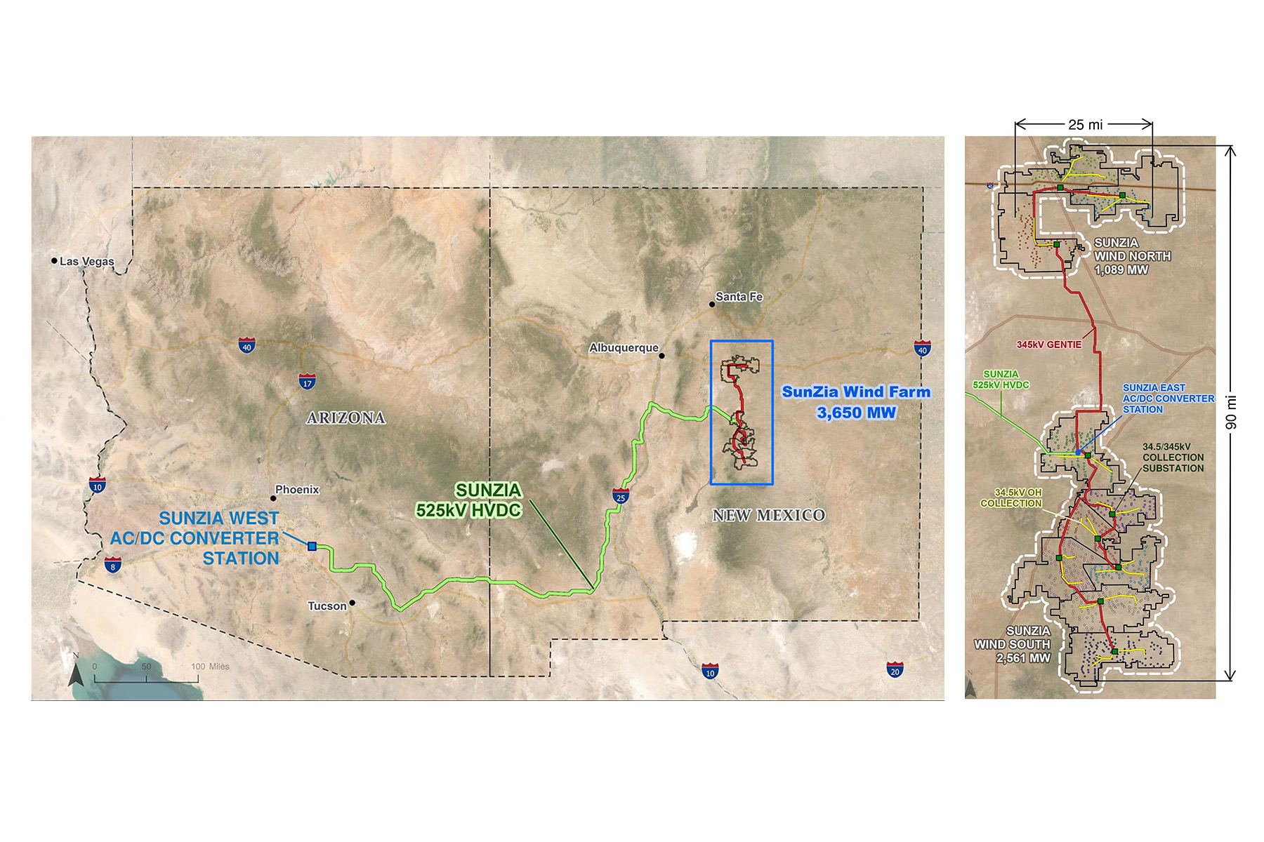
SunZia consists of a 3,650 MW wind farm, the SunZia East alternating current/direct current converter station, a 553 mi 525 kV high-voltage direct current transmission line, the SunZia West DC/AC converter station, and two 500 kV AC tie lines. The wind farm will have 916 turbines, 10 collection substations, 115 mi of overhead collection lines, 130 mi of 345 kV AC generation tie (or gen-tie) lines, and a switchyard. The HVDC transmission line runs west from Corona, New Mexico, to a converter station near Casa Grande, Arizona.
The 3,650 MW of wind generation is initially electrically connected using a 34.5 kV collection system. This collection system consists of underground insulated cables as well as overhead collection lines with noninsulated conductors. This hybrid collection system delivers power to the collection substations. These AC collection substations then increase the voltage from 34.5 kV to 345 kV, and the power is then transmitted on 345 kV gen-tie lines. The gen-tie lines connect to a switchyard where the voltage is increased once more to 500 kV before the power is directed to a massive AC-to-DC converter station. The result is 525 kV HVDC power that is transmitted more than 550 mi to Arizona.
Ulteig, a power, renewables, transportation, and water engineering firm, designed the SunZia wind farm, which includes 245 mi of AC overhead power lines, 700 mi of underground collection line circuits, 10 collection substations, and over 950 mi of access road design. Power Engineers, a division of WSP, designed the 553 mi 525 kV HVDC transmission line.
All generation projects, especially those as complex as SunZia, require the integration of multiple engineering disciplines. Ulteig brought deep expertise to the SunZia wind farm and was selected for the full scope of design services: civil, collection, substation, gen-tie transmission, supervisory control and data acquisition systems (known as SCADA), and metering systems.
Route approval
The most challenging part of this project was the development and approval of the HVDC transmission line route. In 2006, SouthWestern Power Group, an independent generation and transmission developer in the southwestern U.S., began planning an interstate transmission project between Arizona and New Mexico consisting of two single-circuit 500 kV transmission lines and associated substations.
The development and permitting of the HVDC transmission routes took 17 years; contrast that to the design and construction of the line, which took only six years. Route approval is often the biggest bottleneck in developing new transmission lines because of the many approvals required at the county, state, and federal levels.
More than 80 firms, regulatory agencies, utilities, and contractors worked on SunZia during its development before ownership was transferred to Pattern, a multistate renewable energy developer, for final HVDC design and construction.
The basics
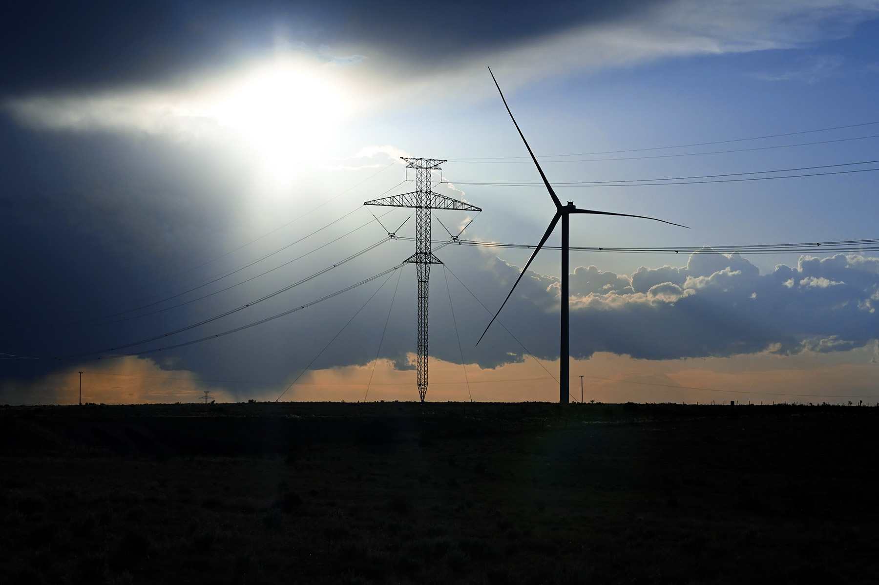
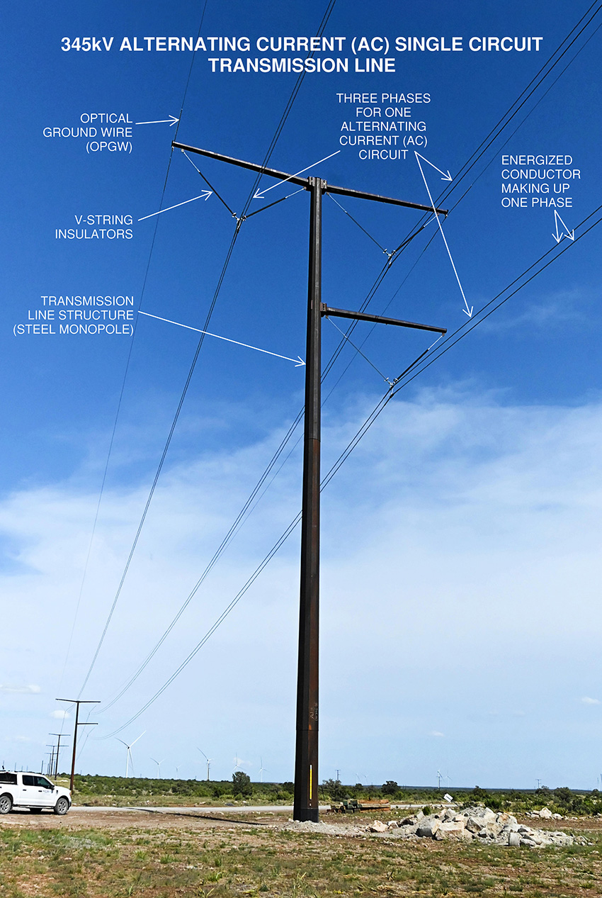
In the electrical transmission industry, a transmission line is a system that includes conductors, insulators, and supporting structures. The structures support the conductors, which are the energized wires, and the insulators, which connect to the conductors. (See page 46.) The conductors have rated breaking strengths in the tens of thousands of pounds, and the supporting structures must be designed to ensure the conductors maintain adequate vertical clearance under various design conditions. The transmission structures must also be designed to resist large conductor tensions from wind and ice and other extreme weather conditions.
Longer spans reduce the number of structures needed but result in greater conductor sag, requiring taller, higher-capacity structures. Shorter spans increase the number of structures but allow the structures to be shorter and lower capacity and to have lower cost per structure. An optimized structure placement plan that minimizes total cost requires iterative designs. Two types of design spans exist: wind span, which determines the transverse loads, and weight span, which determines vertical loads. The figure below shows a profile view of a transmission line and the wind and weight spans.
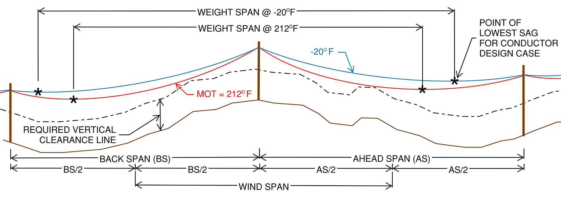
A transmission structure’s wind span is equal to half the distance to the structure behind plus half the distance to the structure ahead. Weight span is dependent on the structure height, topography, and weather conditions. The conductor’s sag and tension vary with temperature, wind speed, and ice thickness. Engineers must analyze numerous design conditions to determine the maximum weight span and ensure adequate ground clearance for the various design conditions. Often, a conductor’s maximum operating temperature results in the largest sag.
Line angle is a measure of the change in direction of the centerline of an overhead power line. The most common type, called a tangent structure, generally has a relatively small line angle (0 to 5 degrees).
Generally, tensions in the ahead and back spans are approximately equal and run in opposite directions, so the effect on the tangent structures is often minimal. Running angle structures generally have a line angle range of 5 to 60 degrees. For both tangent and running angle structures, the conductor is continuous and passes through the end of the insulator.
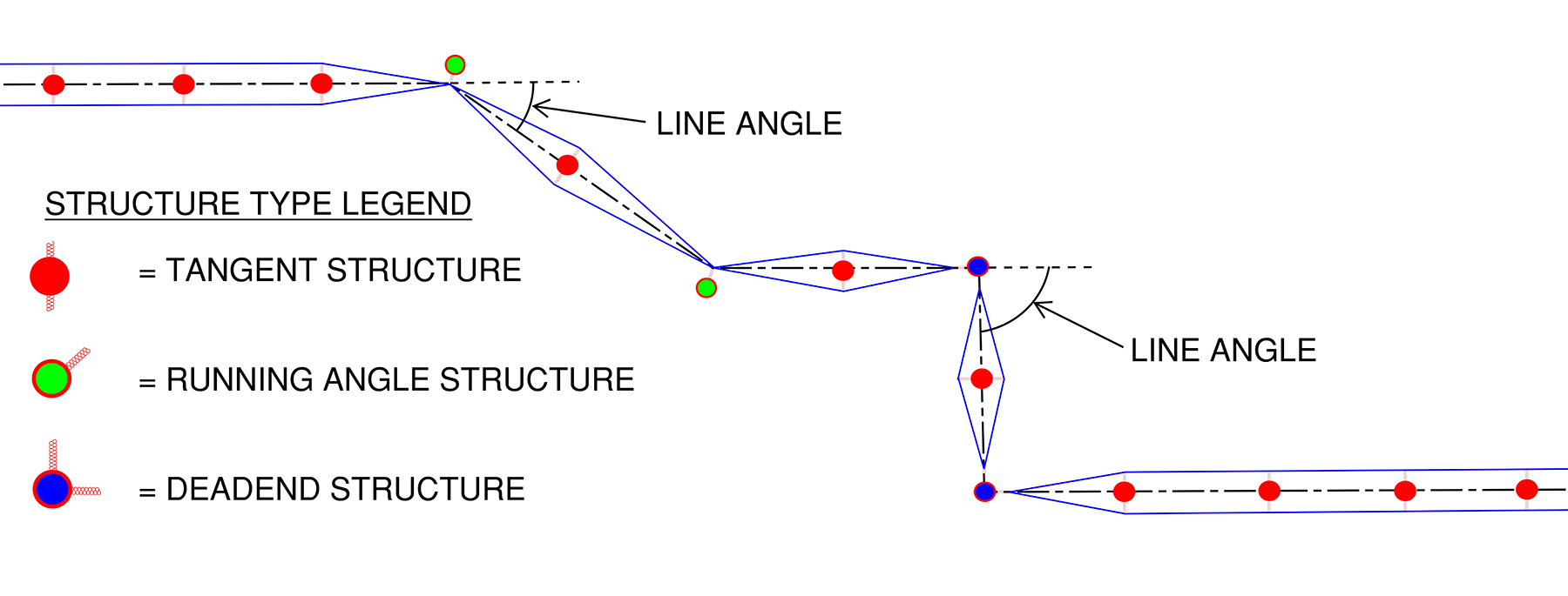
When the conductor terminates on a structure, that structure is known as a dead-end structure. Generally, when line angles are greater than 60 degrees, the structures are designed as dead ends; however, dead ends can occur with any line angle. Large conductor tensions create large transverse loads as the line angle increases.
While vertical loads dominate the design of buildings and bridges, calculating lateral loads is crucial in transmission line design because of the high conductor tensions. Higher line angles result in greater transverse or lateral forces applied to the structure. The table below illustrates the base reactions for self-supporting structures for the three overhead power line types (double-circuit 34.5 kV overhead collection line, single-circuit 345 kV gen-tie transmission, and 525 kV HVDC transmission) used in the SunZia project.
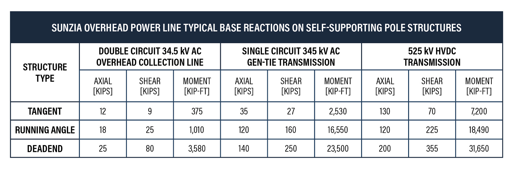
Dead-end structures must resist significant shear and overturning moments. Various structure types are used to resist these types of structural loads, including self-supporting monopoles, H-frames, guyed pole structures, guyed lattice structures, and self-supporting lattice structures. All were used in the SunZia project.
AC versus DC
Power is the product of current (measured in amps) and voltage. A useful analogy can be made with the flow rate of a pipeline. Flow rate is the product of the cross-sectional area and the pressure in the pipe. The cross-sectional area of a pipe is analogous to the current in the overhead power line conductor. The pressure in the pipe is analogous to the voltage. To increase the flow rate in a pipe, the cross-sectional area and/or the pressure must be increased. Similarly, to increase transmission capacity, current or voltage must be increased. For transmission lines, it is generally more cost effective to increase voltage rather than current, as increasing current generally requires larger and/or more conductors.
In the U.S., there was fierce debate over whether AC or DC current is superior. Thomas Edison championed DC, but Nikola Tesla advocated AC because it offered the ability to increase voltage via a transformer. DC power cannot be transformed to a higher voltage; it remains at the same low voltage at which it was generated. The ability to change AC’s voltage made it more cost-effective for transmitting power, leading to its adoption as the global standard.
However, AC lines face challenges when transmitting power over long distances because of the build-up of “reactive power.” A useful visual for reactive power is beer poured into a pint glass. A bad pour will result in liquid beer at the bottom and a significant amount of foam occupying the top of the glass. The foam is like the reactive power: It occupies space but cannot be consumed.
DC transmission lines have an advantage in that they do not develop reactive power. Therefore, the capacity of a DC transmission line does not significantly diminish with length. By combining AC and DC technologies, it is possible to combine the advantages of each technology in the same transmission line.
These lines are known as HVDC transmission lines. Power is generated using AC generators at a relatively low voltage. The AC voltage is then increased via transformers. The high-voltage AC power is converted to DC at a converter station and transmitted efficiently using fewer wires over long distances. At the receiving end, another converter station returns the power to AC before integrating into the existing AC grid.
Despite its advantages, HVDC transmission lines are rare because each converter station can cost hundreds of millions of dollars, making it viable only for large-scale, long-distance projects like SunZia.
34.5 kV overhead collection line
Collection systems can be among the most expensive components of a wind farm project. Most wind farms use insulated cables buried underground. Collection engineers help determine where the cables will go, as well as the most cost-effective locations and number of collection substations.
Collection engineers analyze and model the soil to determine the minimum size of underground cables needed to stay below a maximum operating temperature. Collection engineers also perform comprehensive electrical loss calculations, since most of the losses on a wind farm project are from the low-voltage collections system.
SunZia’s scale, soil type, and topography presented challenges to using a fully buried collection system. Underground collection systems can generally support 25 MW per circuit using insulated cables, while overhead systems, using a similar-sized bare conductor, can support approximately 50 MW because the conductors cool more easily in the open air.
For this project, using traditional overhead collection structures over the course of 115 mi — which required more than 1,600 structures — created unique problems, including a buildup of reactive power, concerns with electrocuting birds of prey, and high quantities of flashovers due to lightning strikes. (Flashovers occur when a surge in voltage causes an uncontrolled short-circuit in which the voltage jumps either from the conductor to the structure, or from the structure to the conductor. Either way, it causes the line to temporarily stop working.)
To solve this problem, Ulteig’s engineers dramatically altered the geometry of the typical overhead collection structures, using an oversized insulator and an innovative conductor type. Engineers found overhead collection to be more cost-effective when more than 70 MW is transmitted along a single route.
SunZia’s layout integrated a blend of short underground circuits connected to long overhead “homeruns,” or long, straight circuits that transmit power from the wind turbines to the collection substation. This hybrid collection system saved an estimated $45 million compared to a fully underground design.
345 kV gen-tie transmission line
A total of 130 mi of 345 kV gen-tie transmission lines were installed to connect the 10 collection substations and deliver the wind farm’s power to the SunZia switchyard. The system used three circuits, each carrying 1,100 MW to 1,300 MW. Optimizing the number and placement of substations was essential to minimize costs, requiring multiple design iterations.
Routing the transmission lines also posed challenges because of land constraints. Ulteig developed an ArcGIS tool called PinPoint to map constraints such as nonparticipating landowners, lease offsets, environmental and cultural exclusions, steep terrain, and turbine fall-down zones, which are circular zones surrounding each windmill where overhead lines may not be built. The goal was to avoid these zones while maintaining straight, cost-effective routes.
Once routes and lengths were finalized, conductor types, span lengths, and structure types were analyzed to reduce construction and life-cycle costs. The contractor, Blattner Energy, an operating company within Quanta Infrastructure Solutions Group, favored steel monopoles and H-frames, prompting a detailed comparison of tangent structure types. Each design was evaluated for span efficiency, insulator and labor costs, and steel component weights, categorized into pole shafts, davit arms, and hardware. Each steel category had a unique fabrication cost per pound, contributing to total cost assessments. The table below shows a relative cost comparison of the different tangent types.
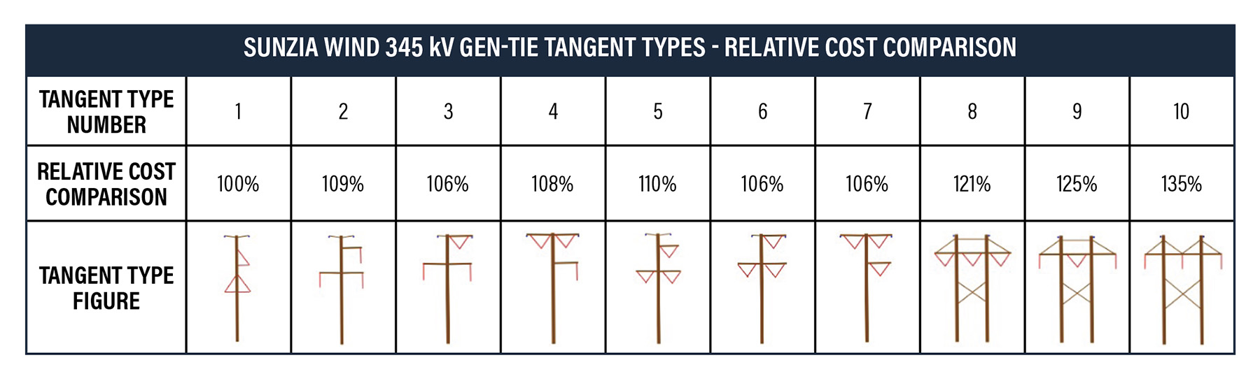
Although the braced-post insulator tangent (number 1 in the table) was the least expensive, its low longitudinal strength was a concern to the owner, so this structure type was not selected. Tangents 3, 6, and 7 had similar costs, but type 7 offered superior lightning protection because of a better shielding angle. This reduced the need for additional ground rods, lowering installation costs. Therefore, tangent type 7 was selected for the SunZia project.
525 kV HVDC transmission line
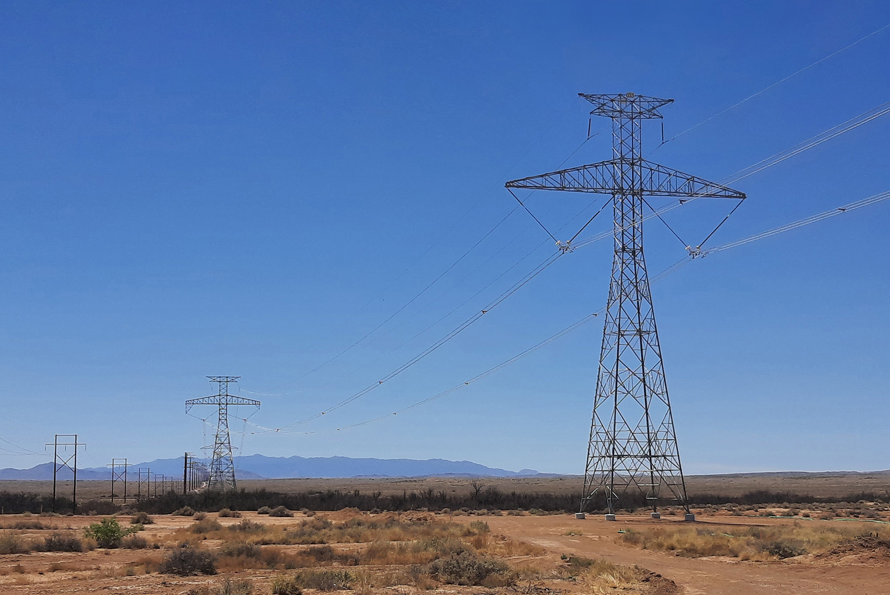
The SunZia 525 kV HVDC transmission line traverses diverse terrain and climates, incorporating nearly 2,200 structures, including lattice towers and steel poles. More than 5,000 grouted anchors support guyed structures with foundations ranging from precast pedestals to drilled piers and micropiles. The line intersects various infrastructure assets in a number of jurisdictions — including the Bureau of Land Management, the Arizona State Land Department, and the New Mexico State Land Office — and includes helicopter-only construction zones and hybrid AC/DC segments in constrained corridors.
The mechanical design followed standard principles for spans, wires, and structures, but the scale and complexity of the HVDC system introduced unique challenges. The line uses two conductor bundles for the primary positive and negative 525 kV DC electrical “poles,” each with three aluminum-conductor, steel-reinforced subconductors (known in the industry as Bluebird subconductors) at 7.5 lbs/ft total per bundle. These were selected for optimal electrical performance and efficiency. The insulator assembly supported by the dead-end structures weighs about 4,400 lbs and is rated at 270 kips tension capacity.
Custom-designed high-quality tempered glass and nonceramic (polymer) insulation and suspension assemblies underwent rigorous electrical and mechanical testing in Europe, Canada, and the U.S. before approval. Factory acceptance testing was conducted for each critical production run. The lattice towers used on the project were designed, prototyped, and tested before any manufacturing began. Some steel poles required for the project were so large that some sections were limited by plant capabilities.
Design was divided into more than 20 segments, managed by a team across 12 offices in 10 states in North and Latin America. Despite the dispersion, the team maintained consistency through centralized data repositories and virtual collaboration tools. Construction was organized into three major work fronts, each with multiple subsegments, material yards, and crews.
At peak, more than 2,000 workers were engaged on the SunZia project. Constraints in certain areas required that construction be accessed by helicopter only, so multiple aviation assets were also used, including helicopter support on each work front to reduce access time to the structures and improve the schedule.
Project impact
When fully operational next year, the SunZia wind and HVDC system will supply reliable and cost-effective electricity to approximately 1.2 million households — serving around 3 million people.
The project is expected to generate $20.5 billion in economic benefits, including $1.3 billion in fiscal impacts for local governments, communities, schools, and landowners in New Mexico and Arizona.
In addition to more than 2,000 construction jobs, it created hundreds of engineering jobs, including those for:
- Electrical engineers (collection system substations, switchyards, converter stations, and transmission line equipment).
- Studies and system planners (wind farm energy modelers).
- Structural engineers (wind turbine towers, turbine foundations, transmission line structures, and substation structures).
- Civil engineers (access road design and turbine pad design).
- Environmental engineers (minimizing and mitigating environmental disturbances).
- Geotechnical engineers (thousands of borings to determine soil properties for the thousands of foundations supporting turbine towers, transmission line structures, and substation structures).
- Materials manufacturing and testing engineers.
SunZia represents an unprecedented scale of power generation and transmission development in the Western Hemisphere. Its successful execution demonstrates that large-scale energy infrastructure can be designed and built in the U.S. within a reasonable timeframe — five years for the wind farm and six years for the HVDC line, with only two years of field construction. However, the most significant bottleneck remains transmission line route permitting: as mentioned earlier, the SunZia transmission line route took 17 years to approve.
As the U.S. anticipates major load growth over the next two decades, accelerating the transmission permitting process will be critical to meeting future energy demands.
Greg C. Parent, P.E., S.E., P.Eng., is a principal engineer for Ulteig. Curtis Symank, P.E., M.ASCE, is a senior project manager for Power Engineers. Man in gray shirt. Evan Bond, P.E., P.Eng., is a lead engineer for Ulteig.
This article first appeared in the September/October 2025 issue of Civil Engineering as “Long-Distance Delivery.”
A more detailed paper and presentation on the overhead power lines of the SunZia project was delivered at the ASCE Electrical Transmission & Substation Structures Conference in Dallas on September 14-18 and published in its proceedings. This conference occurs once every three years and is the most highly regarded transmission line conference in the U.S., attracting roughly 2,000 transmission line professionals.