By Francis Archer, Ph.D., CEng, and Charlotte Briggs, CEng
Exacting detail, careful design, and astounding creativity led to the building of the Grand Egyptian Museum.
In 2002, Egypt’s Ministry of Culture launched an open design competition for a new museum to house its large pharaonic collection, replacing the existing 1902 Egyptian Museum in Tahrir Square.
With more than 1,500 entries, this became one of the largest architectural design competitions ever held. Twenty entries were shortlisted for the second phase, which, like the first, had a rigorous anonymity, with no clues as to the identities of the entrants.
Róisín Heneghan and Shih-Fu Peng entered the competition from their base in Dublin, where they had recently moved from jobs in large practices in New York. They were then a three-person-strong practice managing one project: construction of a building for the Kildare County Council. On being shortlisted, they invited Buro Happold, a global engineering, design, and consultancy firm, for services engineering, and Arup, also an international design and engineering company, for structural engineering input.
When the envelope to identify the winners was opened, no one present had ever heard of this small practice in Dublin. In early 2004, heneghan peng architects, Arup, and Buro Happold formed a joint venture to carry out the design of the Grand Egyptian Museum, which will be the center of excellence for Egyptology for many years.
The site and the winning scheme
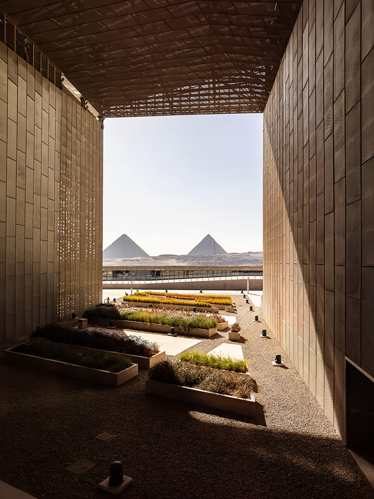
The 50-hectare site, 30 km from central Cairo, commands excellent views of the three historic pyramids of Giza that were built for pharaohs Khufu (his is known as the Great Pyramid of Giza), Khafre, and Menkaure of the Fourth Dynasty. The site straddles two distinct terrains:
- On the west side, a high plateau comprising mainly undulating open desert terrain, having little or no development aside from minor roads and walls.
- On the east side, at a lower level, the western extremity of the former floodplain of the Nile valley that has several one- and two-story buildings.
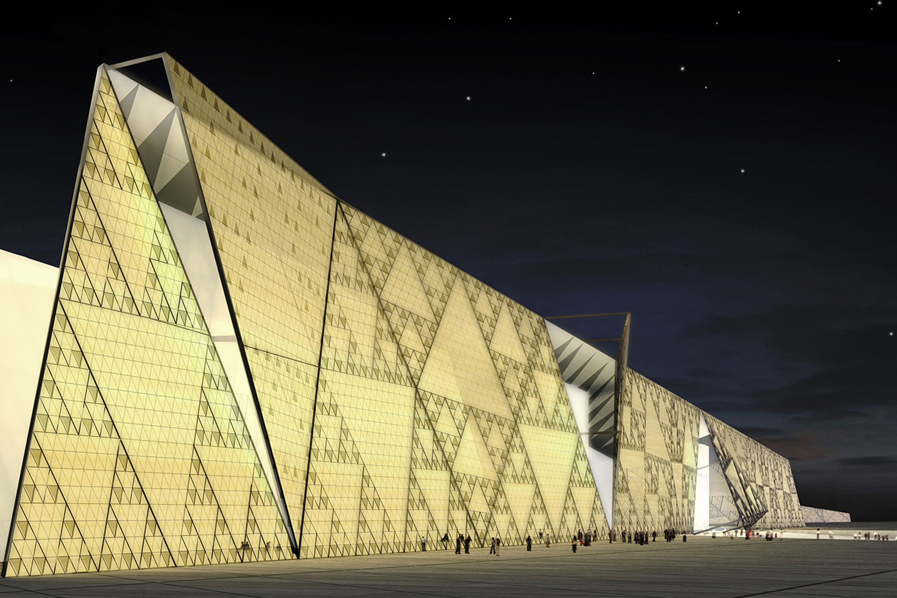
There is a 40 m difference in elevation from the eastern boundary to the western boundary. Steep escarpments or slopes like this are prominent features of the area, with the remaining undeveloped land on the Nile delta being lush and green and the desert plateau beyond being devoid of vegetation. These natural site conditions were incorporated into the winning scheme to achieve a design that is grand yet respectful of the natural landscape and the pyramids. This was achieved by inserting the large building massing into the escarpment; its roof is aligned with the desert plateau level, disguising its vast form within the natural environment.
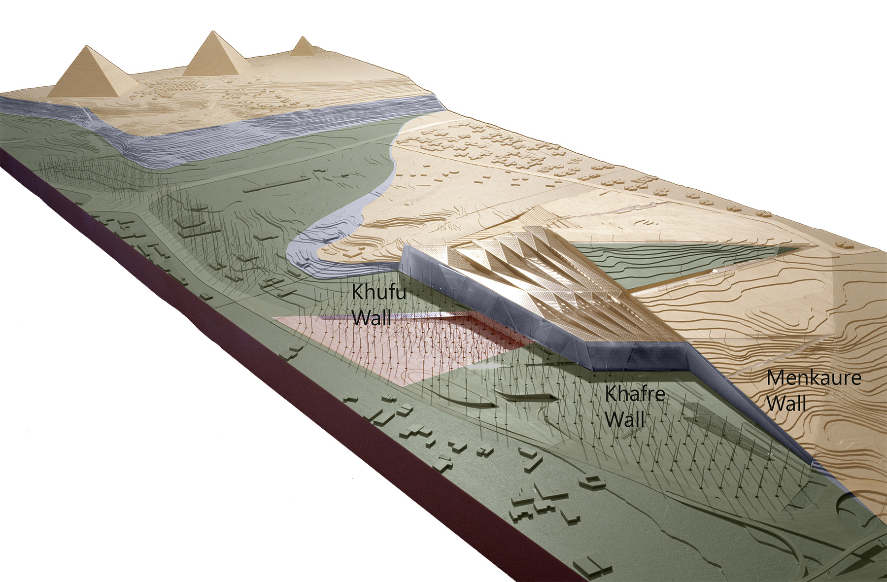
The prominent eastern facade of the building massing thus forms a new escarpment. To achieve this concept, significant regrading of the site was required. Millions of cubic meters of sand were moved and eventually replaced behind a new reinforced-concrete retaining wall to the west of the Main Buildings. This earth-retaining structure, known as the Menkaure Retaining Wall, is 500 m long and up to 35 m in height. It was designed with an embedded base and counterforts up to 25 m wide.
The project
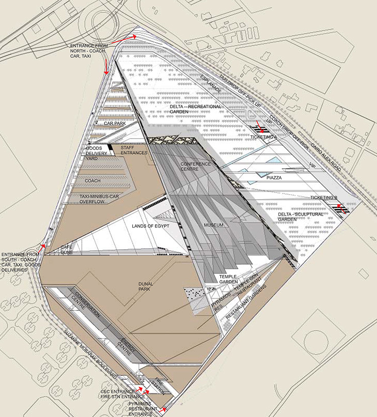
The complex consists of nearly 100,000 sq m of construction and has 35,000 sq m of exhibition space. The Museum Building and the Conference Center (referred to as the Main Buildings) are independent reinforced-concrete-framed buildings under a single roof structure, with a central court in between.
The Conference Center’s footprint is approximately 140 m by 110 m. It is a four-story building with the ground floor at +25.5 m above sea level, the main foyer and auditorium at +33 m, a large mezzanine floor of office space at +39 m, and additional office space and roof garden at +43.5 m. The reinforced-concrete folded-plate roof is above this level.
The footprint of the Museum Building is approximately 190 m by 210 m. Toward its northern end, it is a four-story structure founded at the same level as the Conference Center. The ground level “steps up” as the building extends southward, with intermediate sections of the building having three or two floors and the southernmost section being a single-story structure with a floor-to-ceiling variance of 3 m to more than 20 m. The reinforced-concrete folded-plate roof covers the building entirely.
The single large massing was created using a lightweight environmental envelope composed of a variety of horizontal and vertical structures:
- Steel shading mesh roof over the concrete buildings.
- Steel roof structure extending beyond the building footprint to the south over the Temple Garden to form large overhangs beyond the south-facing gable-end glass facade.
- Steel roof structure spanning between the two buildings to form the entrance court.
- Steel roof structure beyond the north of the Conference Center to form the food hall court.
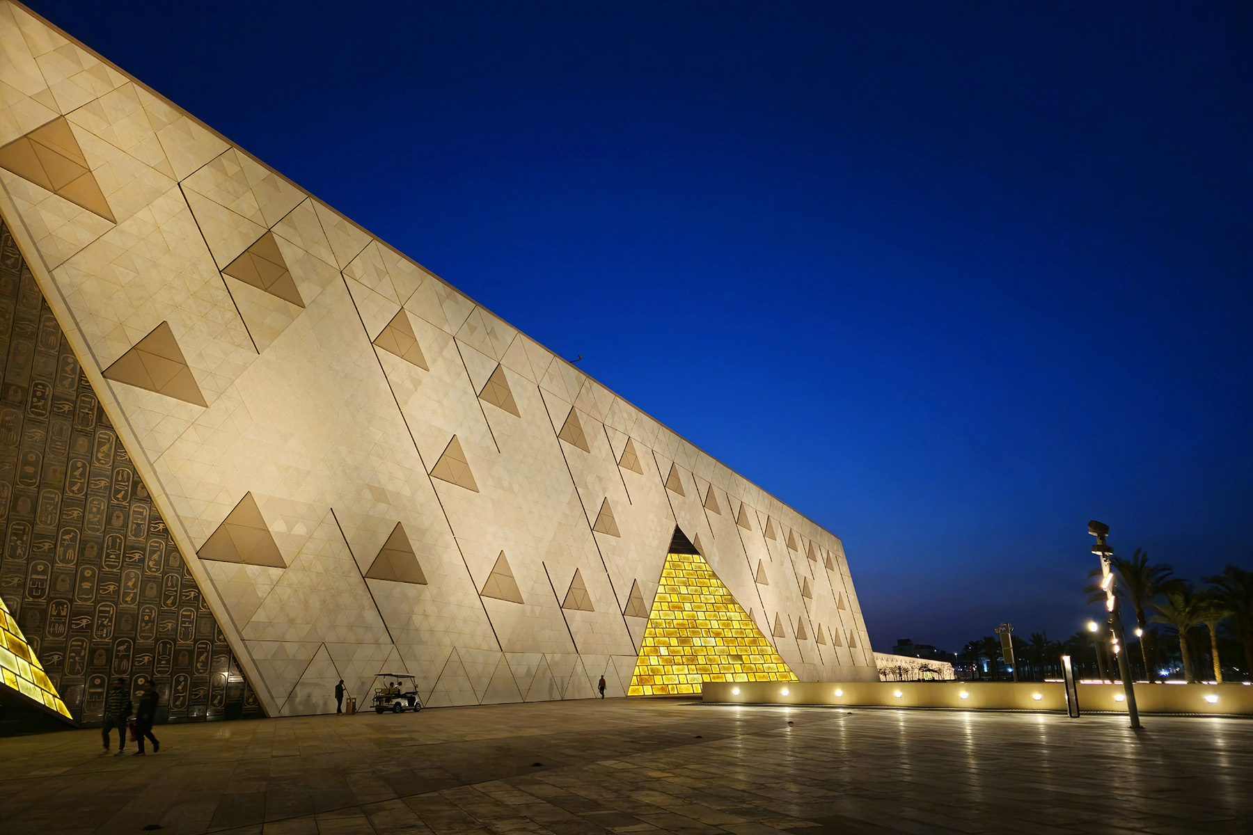
- Translucent stone wall wrapping around the building to the east and north.
The project consists of many other smaller buildings as well. Most of these are back-of-house buildings to the west of the Menkaure Retaining Wall and are connected to the service access area to the west. These include:
- The 16,000 sq m Conservation Center as well as the power and fire stations buried under sand on the southwest side of the site.
- A 200 m long artifact delivery tunnel buried up to 15 m below landscape level that connects the Conservation Center to the main upper gallery level of the Museum Building.
- A staff entrance building buried under the western landscape.
- The Temple Garden restaurant to the south, which provides excellent views of the pyramids while remaining low enough to not obstruct the same view from the museum gable-end facades.
- Small ticketing buildings to the east.
In addition to these buildings, there are many landscape structures varying in size from the 35 m high earth-retaining walls to smaller long retaining structures, enabling the landscape design across the lower eastern zone of the site and on the higher western side.
The landscape and building structures were primarily constructed using in situ reinforced concrete, typically using walls for stability.
The grid
The design is fundamentally geometric, consisting entirely of straight lines and no curves. Inspired by the perfect north-south-east-west alignment of the pyramids, the designers opted to lay across the entire site a 24 m by 24 m orthogonal north-south-east-west grid. Radial lines connect the nodes of the orthogonal grid to a setting-out point just north of the site, which was geometrically dictated by the locations of the Menkaure and Khufu pyramids approximately 1.5 km south of the site. The perfect alignment is thus respected strictly in the project grid.
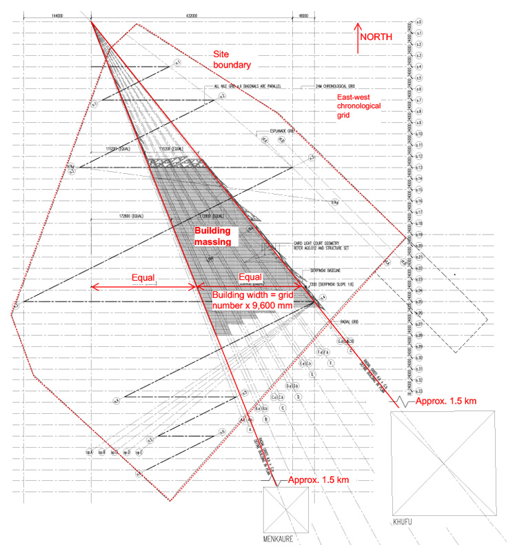
The Main Buildings complex is bounded by these two radial lines: The set of parallel east-west grid lines, known as the chronological grids, were used to lay out the main exhibition’s pharaonic chronology.
Additionally, the grid extends into the third dimension via a similar vertical module that defines the building massing bounded by the ground plane and a southward-rising plane aligning to the highest point of the Great Pyramid.
The project team devised a rigorous set of rules for laying out all the building components, ensuring coherence of design across the entire project. Thus, every single visible line in the finished building — be it stone paneling on the walls, floor finishes, stair treads and risers, soffits, ceilings, or roofs — is “on grid,” and the easting (x), northing (y), and elevation (z) coordinates of every one of these points is a rational number in millimeters that can be calculated from a simple set of linear equations.
The entire structure was modeled in MicroStation BIM. On being appointed, the contractor — a joint venture between the Besix Group and Orascom Construction — added all architectural and services components to the global BIM model.
All drawings aligned to the grid system, resulting in all the elevations and sections being drawn in either east-west sections or north-south projections. This enabled rule-bound drawings of all elements and ease of checking coordination simply by overlaying the grids.
Though geometrically non-orthogonal, the Main Buildings within the environmental envelope are primarily of traditional construction, consisting of:
- Shallow reinforced-concrete strip and pad foundations.
- Ground-bearing floor slabs and earth-retaining walls as the ground plane steps upward.
- Vertical walls and columns carrying vertical loads and acting as shear walls to resist horizontal loads. As with all other elements, the geometry of the columns is defined by the grid system.
- One-way spanning systems of primary and secondary floor beams and slabs.
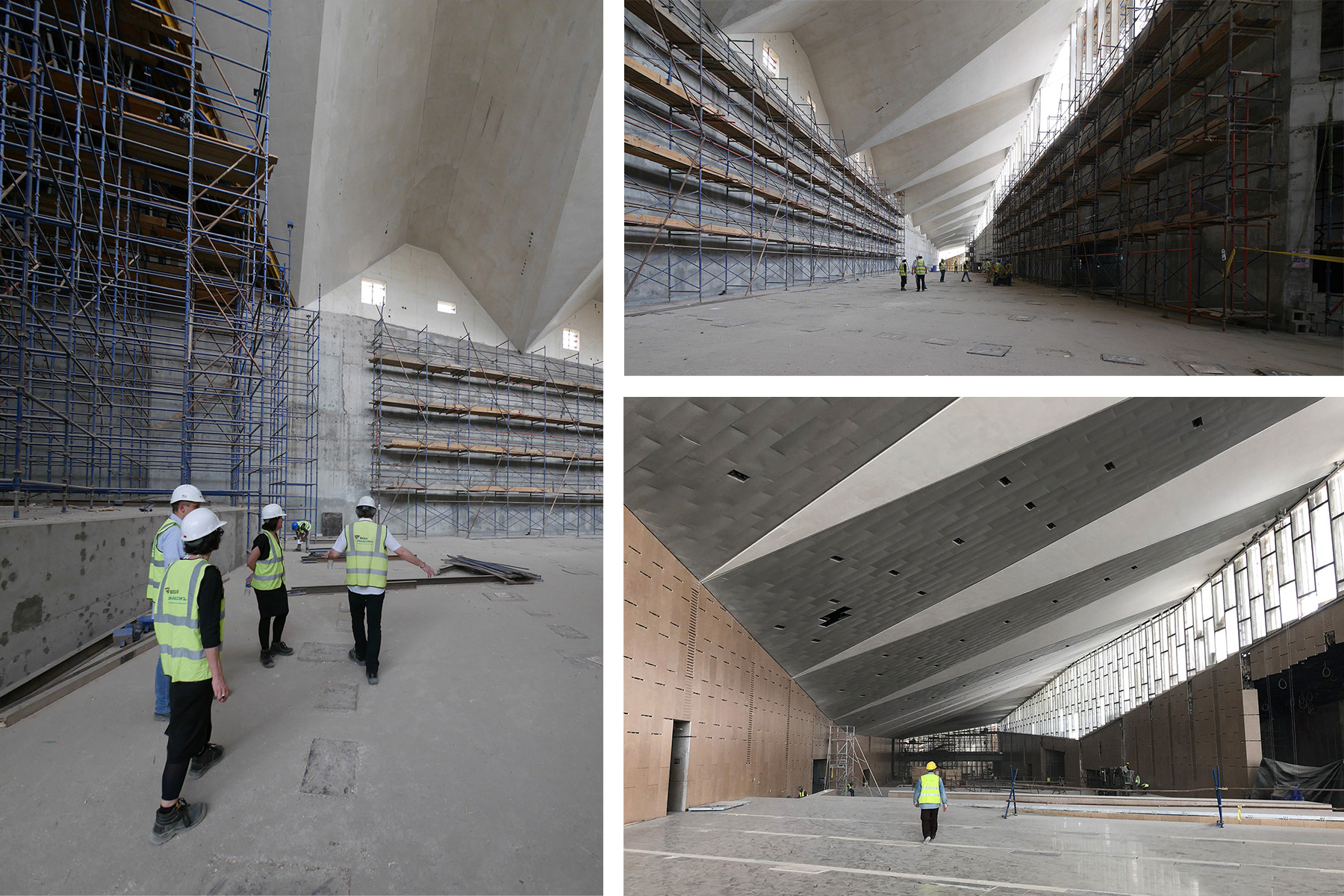
- A folded-plate, long-span concrete roof that has local posttensioning in the zones of the longest spans.
The Grand Egyptian Museum holds a unique collection of artifacts, many of which are primarily stone and potentially heavy enough to dictate the design of the floor structures, as well as walls, columns, and foundations.
For this reason, the project team believed it was important to undertake a study of the collection prior to deciding the floor design loading strategy and the design of the building structure.
Museums are often able to display heavy items (e.g., tanks or trucks) on a ground-bearing slab, but the main gallery floors for the Grand Egyptian Museum are primarily suspended floors, spanning between walls and columns.
This is to facilitate the extraordinary views of the pyramids directly from the gallery floorplates and to celebrate the height and form of the folded-plate roof structure.
To assess the scale of the challenge, data sheets were provided for more than 800 heavy artifacts that were to be housed in the museum, including stone structures up to 25 m in height and totaling thousands of metric tons in weight. This database was used to develop the hierarchical design approach for the gallery structures.
In addition to supporting heavy artifact loading, an underfloor plenum for distributing air was preferred due to the high ceilings.
A holistic design approach led to a double-slab solution, mimicking a raised-access floor system but with the benefits of additional structural depth and floor-loading capacity. This was replicated in concrete for the shorter spans and in steel for the longer-span zones.
The design of each of these elements was rationalized to provide a reasonable level of flexibility while avoiding excessive material use. The design team created a guide to define both the location and movement requirements of various artifacts based on their size and weight. The floor system was designed to accommodate smaller, lighter artifacts throughout, while heavier artifacts required careful positioning and additional plinths to load the beams or columns directly, with minimum spacing defined between the artifacts so as to avoid overloading individual bays.
Through this method, fewer than 10 of the original heavy artifacts were identified as requiring strengthening of the typical structure once their final locations had been chosen.
The folded-plate roof spans across the uppermost level of the Main Buildings with east-to-west spans up to 40 m. To ensure the clerestory windows on the east of each gallery let in natural light, the structural depth tapers from west to east, with a corresponding increase in width of the exposed white concrete lower flange zones of the folded plate. Between these zones is a deep ceiling zone to hold lighting and accommodate the smoke extraction zone.
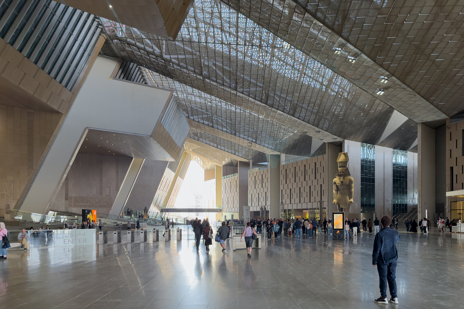
The steelwork atrium roof continues the geometry of the folded plate roof and spans across the entrance court between the buildings. It consists of long-span primary trusses and tapering secondary trusses fabricated from a mixture of open- and closed-steel sections. This steelwork was then wrapped in perforated steel cladding inside and outside.
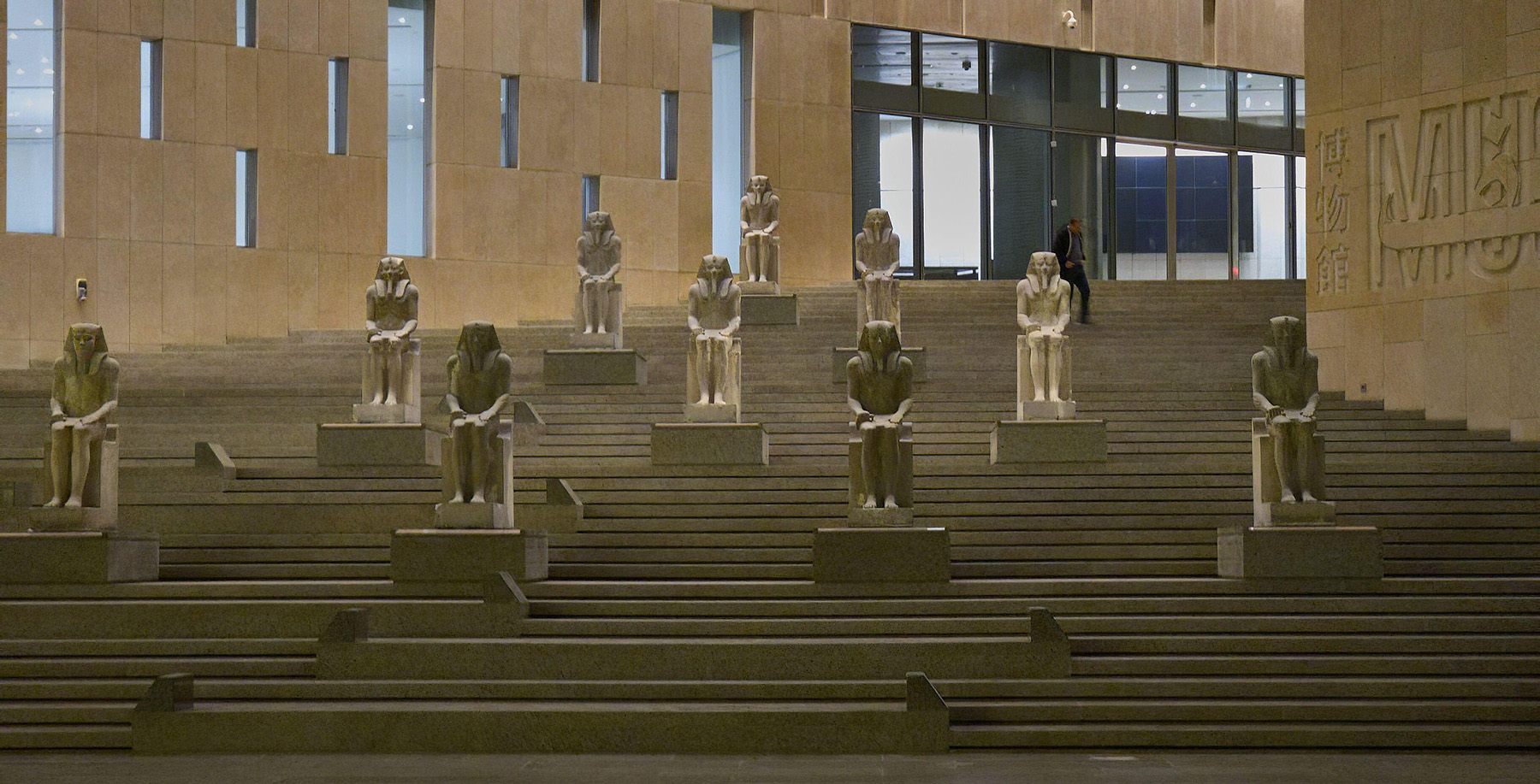
The grand stair traverses a 24 m height from the entrance foyer up to the gallery level. Heavy artifacts are displayed on landings and plinths, making this a major gallery in itself. Adjacent to the stair, which begins at a width of 100 m, is an inclined platform lift between main landings.
At the south end of the Museum Building, each of the six gallery bands has a large, glazed facade looking directly out at the pyramids. These facades are up to 24 m high and up to 42 m wide. The 4.5 m tall glass panes within the facades are held up by vertically tensioned 20 mm diameter high-strength locked-strand cables, each carrying up to 300 kN between a roof-level steel truss and a floor-level deep steel beam. To avoid excessive torsion in the corner panes, the vertical edges of these facades are allowed to sway out of plane with a brush detail built into the adjacent walls.
A planned element not part of the final construction is the translucent stone wall, which would wrap around the east and north building facades, creating a naturally illuminated screen along the new juncture between the green valley and the desert plateau.
A bespoke structure, the wall would consist of triangular steelwork megaframes up to 55 m in height that would act as a rigid frame against which steel cable net structures would be tensioned. The stone panels would then be supported vertically and horizontally from the cable nets.
The groundworks and supporting structures have been installed should this be incorporated in the future.
Geotechnical and construction details
The foundation system for the Grand Egyptian Museum comprises strip footings of variable width — all based on an iterative settlement calculation procedure set up specifically for the project using in-house and external software and Eurocode.
The governing factor in the design of the 500 m long, 35 m tall Menkaure Retaining Wall was its extreme height in combination with seismic-loading conditions. The design of the wall began by benchmarking published equations for rigid-body seismic loading (applicable to the gravity-
retaining system adopted for the Menkaure Retaining Wall) programmed into an analytical sheet in Microsoft Excel through 2D-finite element calculations performed in Oasys SAFE.
Following the good agreement achieved between these two approaches for equivalent design cases, all design combinations for this retaining wall were progressed using the analytical sheet.
Construction of the Conservation Center and power station began in 2007. This early construction phase was procured through a local all-Egyptian contract and was an important step for the years of work that would be required for the Conservation Center personnel to clean, catalog, and restore all the artifacts before being put on public display in the museum.
The main construction contract was signed in 2011. The colossal retaining structures followed suit, paving the way for the construction of the Main Buildings.
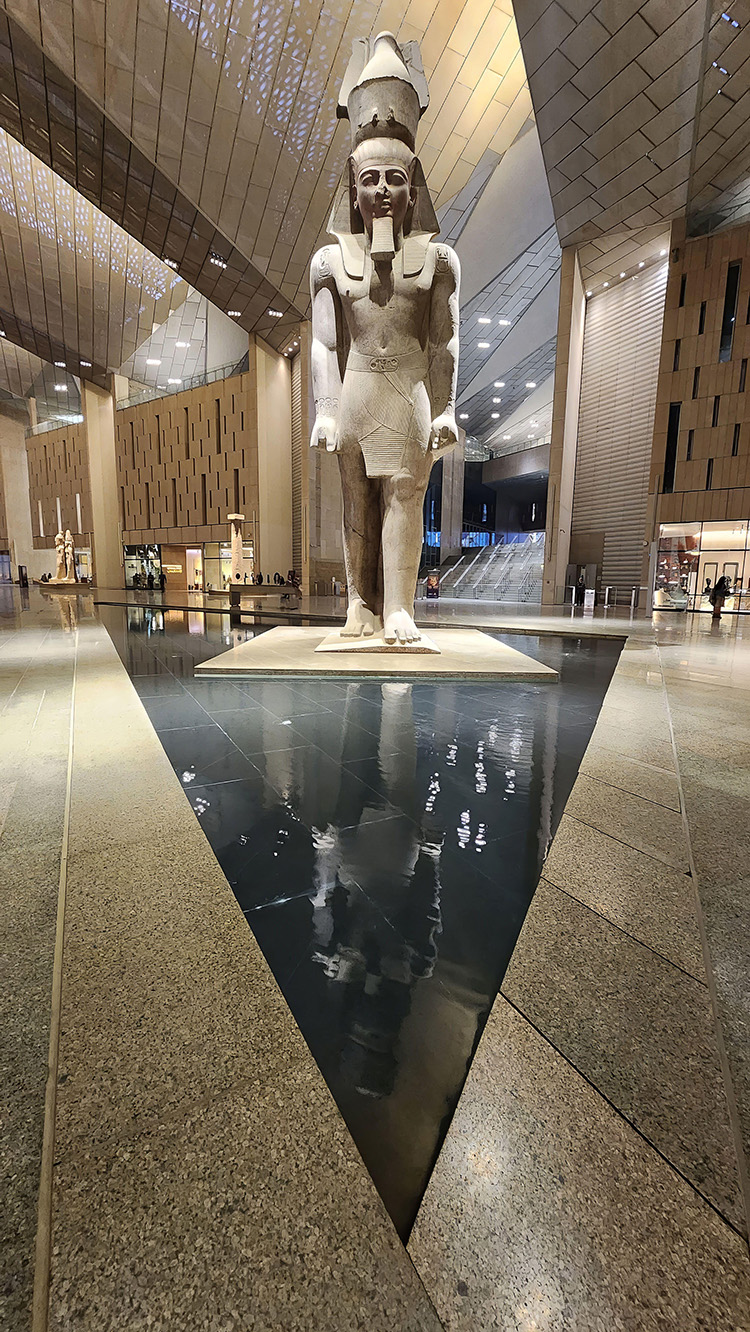
Amid much excitement and celebration, the 11 m high, 83 metric ton statue of Ramses II was relocated to pride of place in the entrance foyer in 2018, once the steel roof had been completed between the two buildings.
Some exhibits were opened to visitors in 2024, and a museum-wide opening occurred November 1.
Francis Archer, Ph.D., CEng, is an associate director and Charlotte Briggs, CEng, is an associate in Arup’s London office.
Project credits
Architects
heneghan peng architects, Dublin
Raafat Miller Consulting (rmc), Cairo
Structural, civil, and traffic engineering
Arup, London office
Arab Consulting Engineers, Cairo
Building services
Buro Happold, Bath, England
Shaker Engineering, Cairo
Landscape architecture
West 8, Rotterdam, The Netherlands
Sites, Cairo
Design team management and cost consultant
Davis Langdon, London
Facade engineering
Arup, London office
IT, security, fire, and acoustics
Buro Happold, Bath, England
Specialist lighting
Bartenbach Lichtlabor, Tyrol, Austria
Signage and wayfinding
Bruce Mau Design, New York
Exhibition master planning
Metaphor, London
Museology
Cultural Innovations, London
This article first appeared in the November/December 2025 issue of Civil Engineering as “Lines in the Sand.”

