By James M. Phillips III, P.E., and Barry Keung, P.E.
Scotland’s Renfrew Bridge balances design, efficiency, and constructability.
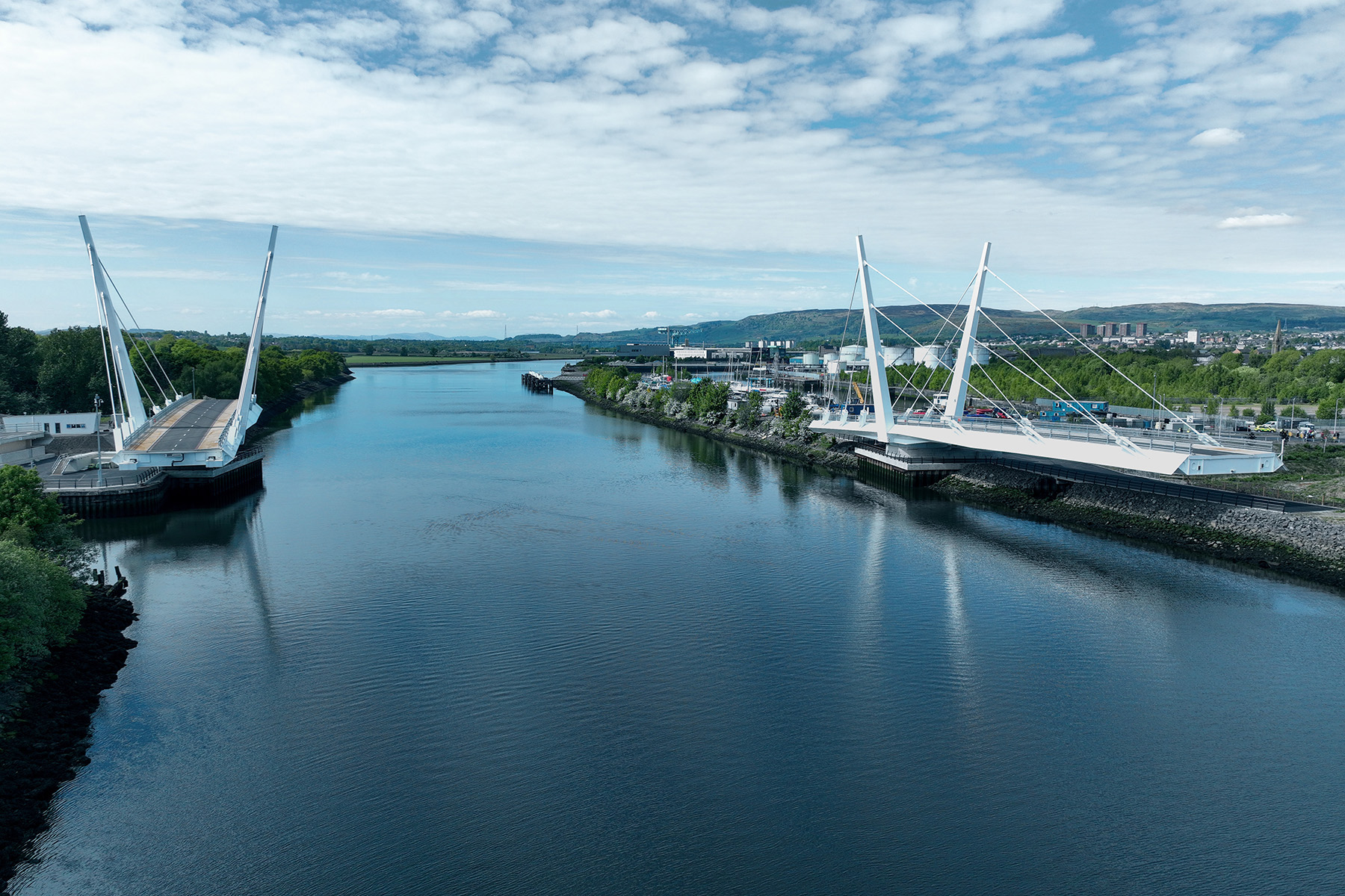
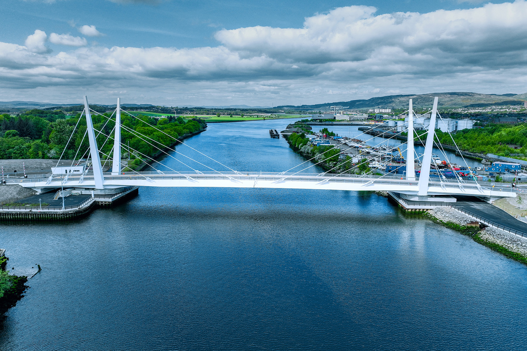
Renfrew Bridge is a stunning double-leaf swing bridge that links communities on both sides of the River Clyde in Renfrewshire, Scotland. The 184 m long bridge provides a much-needed route from Yoker ScotRail station to Inchinnan Road along Dock Street, facilitating quicker travel to Glasgow Airport.
The project site was chosen because of the road connection with Argyll Avenue, a residential connector street, which allows drivers to circumvent the Renfrew Golf Club, giving pedestrians and cyclists a direct path to green space and cycle routes.
Renfrew Bridge, completed in 2025, is the centerpiece of the Clyde Waterfront and Renfrew Riverside project. CWRR is just one of the ways that the U.K. and local governments are prioritizing infrastructure to drive economic growth along with capital investment programs to attract business development.
H&H was the lead movable bridge and slewing machinery systems designer for the landmark infrastructure project, which ushered in a new era for the region and revitalized the riverside community.
Specimen design
For the design-build delivery of the bridge, Renfrewshire Council began with an invitation-to-tender process. A joint venture of Kettle Collective, Cass Hayward, SWECO, and KGAL developed the project’s specimen design, which consisted of a double-leaf bobtail cable-stayed swing bridge across the River Clyde.
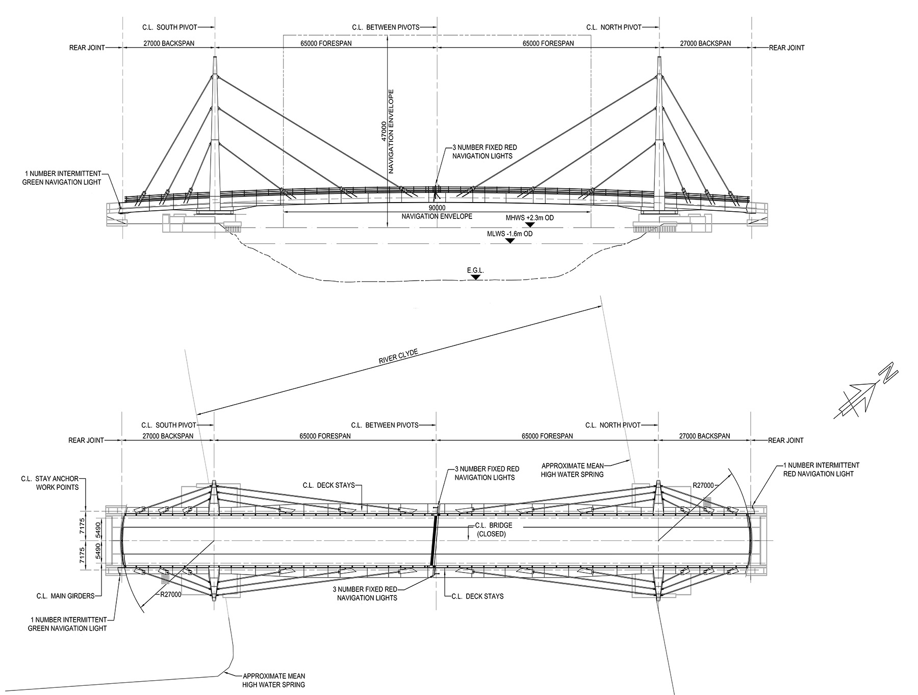
Since the topography of the area surrounding the bridge is relatively flat in elevation, the at-grade connection points of the crossing are low in elevation. It was imperative to maintain the River Clyde as an active waterway, so the design team chose the double-leaf bobtail swing bridge because it could accommodate a low roadway profile while providing a 90 m wide navigation channel clearance and unlimited vertical clearance.
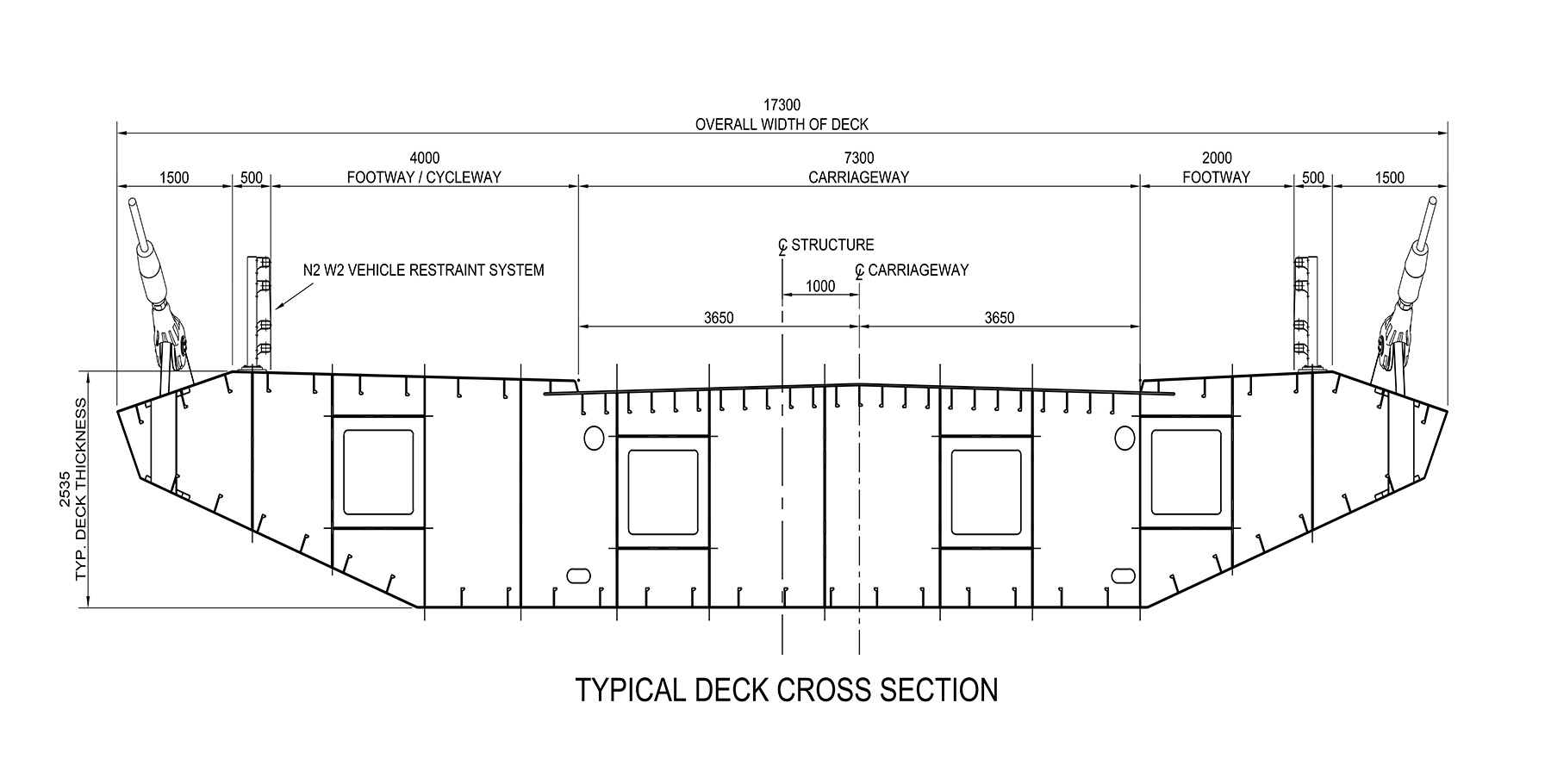
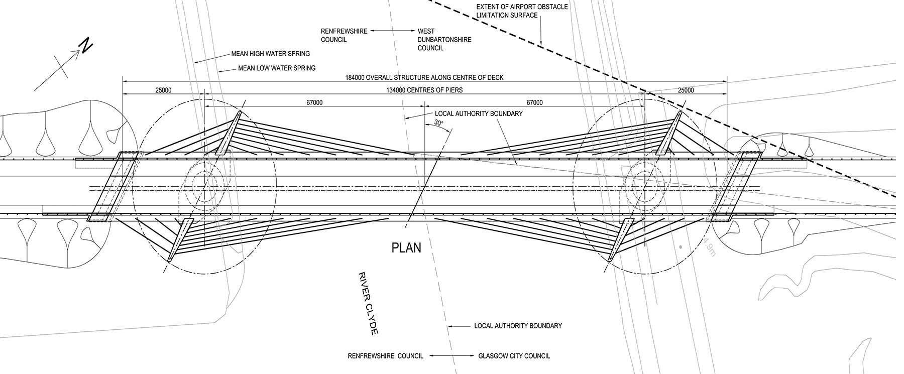
The roadway cross section of the specimen design consisted of a two-lane 7.3 m wide carriageway and asymmetric footways/cycleway of 4 m and 2 m, respectively. The specimen design for the swing bridge shown in Figures 1 and 2 consisted of pairs of cable-stay pylons skewed 30 degrees to the direction of the roadway with 22 stays per leaf: seven forward stay cables and four rear stay cables per pylon.
The stay cables supported a single 17.3 m wide orthotropic box deck span (Figure 1). The forward and rear deck spans of the swing were arranged in a bobtail configuration with the forward and rear spans set at 67 m and 25 m, respectively. The forward and rear deck joints were arranged in a linear arrangement at the same 30-degree skew to the carriageway to mirror the pylons (Figure 2).
Detailed design
For the detailed design and construction of the bridge, Renfrewshire Council awarded a design-build contract to a team led by GRAHAM Construction, which subcontracted the delivery of the swing span superstructure and machinery to a joint-venture team led by Hollandia Infra and Iemants. The swing span constructor’s scope was split between these two fabricators, with Hollandia Infra fabricating the south swing span and Iemants fabricating the north swing span. H&H and ROD were the prime designers of both swing spans for this joint venture.
An initial phase of the design-build process implemented value engineering measures to reduce construction costs and improve the constructability and fabrication of the steel superstructure and the movable bridge kinematics of the swing spans.
At 130 m between pivots, the movable span is large for a bridge of this type. The length and double-swing configuration presented design challenges. A driving consideration during detailed design was the potential variability in the swing span structures’ geometry due to thermal changes and how they were to be controlled and/or accommodated in the operation of the bridge.
For single-swing span bridges, thermal gradient-induced deformations can be controlled by lifting the ends of the swing span at the adjacent fixed piers or abutments with end wedges or similar devices. However, a double-swing span’s ends do not have the luxury of a fixed support; they must be aligned upon closure of the spans, and the nose locks must be able to secure the deck at midspan. The design team solved this issue by developing a bridge-specific operating sequence and support system that allows the operating mechanisms to accommodate variability in the deck geometry due to thermally induced movement, including that of temperature gradients in the structure.
The system includes a pair of wedges at the rear of each swing span that jack the rear down against a pair of fixed bearings prior to engaging the nose locks. This combination of wedges and bearings positions the rear deck of the swing span to align with the abutment deck under all anticipated thermal conditions. Wedge operation and sequencing allowed the designers to establish the position of the nose of each span with confidence and design the nose locks to accommodate the potential variability in the deck elevations on either side of the nose joint.
On fixed bridges, thermal expansion and contractions can be managed with traditional modular joint systems; however, on a movable bridge, moving and static elements need proper clearance for bridge operation. In anticipation of this, the design team evaluated the differential deflections at critical interfaces in all three axes.
Additionally, the team ran a thermal analysis of the detailed design model to account for a differential gradient between swing spans rather than a single coincident temperature range for both structures. Most notably, the design-build team opted to install a hydraulically operated modular deck joint at the nose of the south span. This joint was designed to retract to provide the necessary clearance for bridge rotation. When the bridge is not open, the joint remains closed to provide a consistent threshold between leaves for pedestrians and vehicular traffic. To account for deck movement due to thermal expansion and contractions, a hydraulic accumulator passively maintains pressure on the system to keep the joint closed.
A key factor in efficient movable bridge design is managing the movable span’s weight. Heavier superstructures require heavier counterweights to balance the moving bridge. So, even perfectly balanced spans are subject to increased mechanical demands, as heavier superstructures result in increased inertial forces.
H&H and ROD began tender design by optimizing the geometric complexities of the specimen design, which would impact the fabrication and cost of the structure. The extreme 30-degree skew of the forward deck joint resulted in a 7.5 m overhang of one deck end and imposed a large transverse imbalance on the deck span. This transverse imbalance would induce torsional loading of the deck span during operation, which could affect the bridge’s kinematics and alignment during operation.
During the detailed design phase, the H&H team decreased this skew from 30 degrees to 6 degrees, resulting in a 6.6 m reduction of this overhang, greatly decreasing transverse imbalance effects on the superstructure and the bridge’s slewing bearing. The 30-degree skew of the cable-stay pylons was eliminated, and the pylons were set perpendicular to the roadway, greatly simplifying stay geometry and loading (Figure 3).
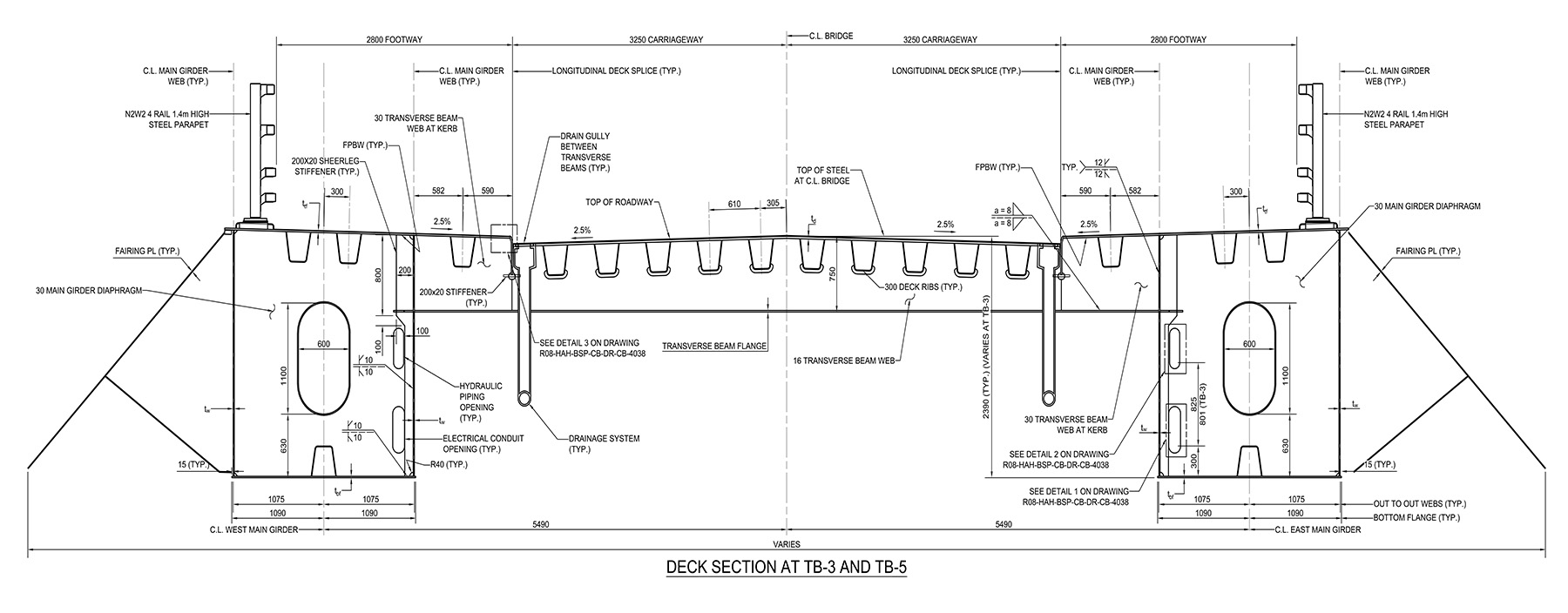
Through value engineering, the design team narrowed the deck section from 17.2 m wide to 13.2 m wide after optimizing the geometric complexities. The arrangement of the deck section was converted from a single orthotropic box to a more conventional and economical two-girder transverse beam system. These simplifications improved fabrication, constructability, and accessibility throughout the deck superstructure. Converting the deck span to a traditional framing arrangement improved the inspection and maintenance of other bridge appurtenances such as scuppers, curbs, and orthotropic deck troughs (Figure 4).
The primary structural support for the superstructure combines a cable-stayed system with the deck framing. This efficiency significantly reduces the amount of steel on the swing span compared with a traditional truss or girder system. Supporting the bridge deck with high-tension cables efficiently transfers loads to the supporting pylons, resulting in a leaner and lighter structure.
The orthotropic deck system consists of steel deck plates that are longitudinally stiffened by deck ribs, integral with the transverse beams. These ribs contribute to the bending resistance of the deck plate by acting as stiffeners and increasing the total cross-sectional area of the steel. This allows vehicular wheel loads to be distributed to the main girders and contributes to the structure’s overall load-bearing capacity. While these features are also inherent to a concrete deck slab, the steel orthotropic deck is much lighter. This considerable reduction in weight extends to all elements of the structure, including cables, towers, and piers.
Compared with the specimen design, these strategic modifications greatly reduced the overall weight of the movable span, which had precipitous effects on the rest of the bridge design. The lighter structure decreased material costs, improved the efficiency of movable bridge operation, and reduced the amount of counterweight required for the swing spans. With these efficiencies, the team consolidated the number of cable stays from 22 per leaf to 12.
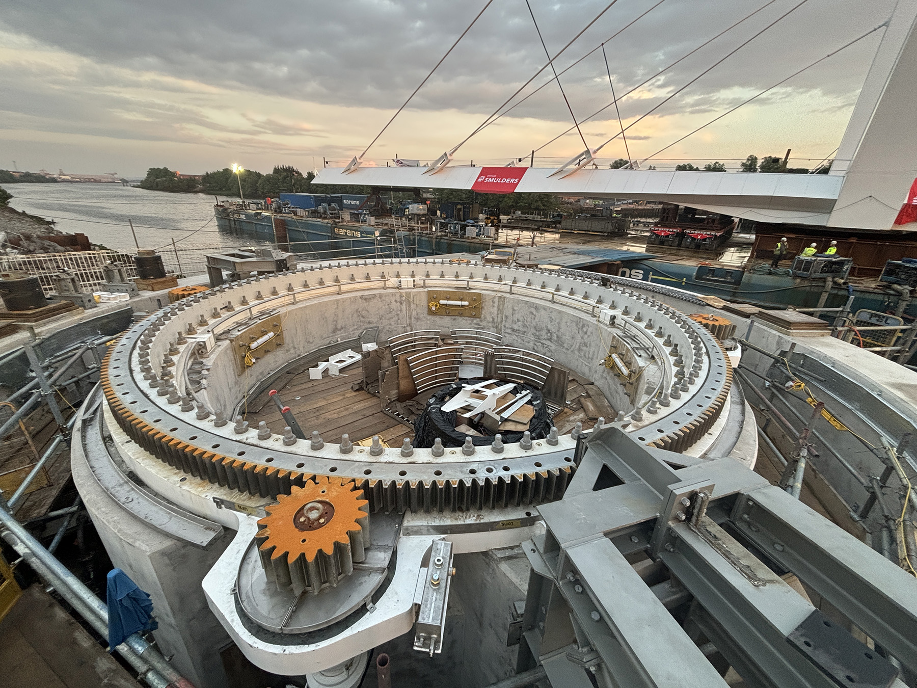
A major advantage of having such a lightweight structure was being able to use commercially available specialty items rather than custom fabrications. The center pivot-support mechanism of the swing span is a large-diameter, gear-driven, triple-roller slewing bearing typically used in the industrial crane and wind turbine industry. This slewing bearing type permits smooth rotation of the span while supporting high vertical and overturning loads.
Traditionally, on older swing spans, this center support system consists of a large cast-bronze thrust bearing with balance wheels to resist overturning. The slewing bearing of the Renfrew Bridge is outfitted with a circular rack and is operated by four pinions powered by hydraulically driven slewing drives set in a planetary arrangement.
As the major support mechanism of the swing span, this slewing bearing is the most important element of the bridge in terms of bridge installation, replacement cost, and potential disruption to operation. Its use in the design simplified bridge installation by reducing the number of alignment points and mechanical interfaces that required field verification.
To further facilitate future maintenance and potential bearing replacement, jacking point stiffeners were integrated directly into the swing span superstructure. Using commercially available jacks, the span can be lifted in place, enabling bearing replacement without requiring extensive disassembly or demolition.
Digital twin
In general, movable bridges require a higher level of detailing during the design process, as moving elements require specific clearances with static elements. These initial design clearances are compounded when accounting for operational loads, wind loads, thermal expansion, steel fabrication tolerances, and site erection tolerances. Because the movable spans were entirely shop-fabricated, field adjustments at typical bolted splices would not be possible to account for tolerances.
For the design-build team to deliver a complex long-span structure, preconstruction planning was critical. The team used modern tools to overcome several challenges. For instance, the project’s owners are in Scotland; the the design teams are in the United States, the UK, Ireland, and Austria; and the fabrication teams are in the Netherlands and Belgium. The language and geographic barriers across the workplaces meant that communication played a major role in the success of the overall project.
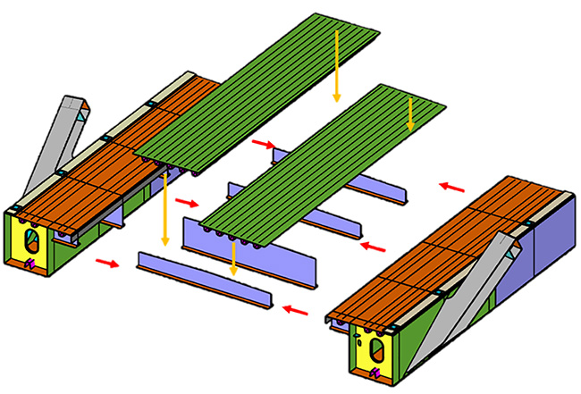
Although traditional 2D drawings and sketches were circulated among the teams as formal contract drawings and communication, 3D models and views were critical to maintaining a strong understanding among all groups. To achieve this, the design team detailed in 3D nearly all the steel plates and mechanical components of both bridge leaves to Level of Development 400, ensuring that the fully welded steel structure was fabricated as the design intended.
The design team parametrically created a CADD model in Autodesk Inventor for coordination with the fabrication team and the production of 2D contract drawings. The global structural analysis model of the bridge was developed in parallel in MIDAS. Local stress shell analysis models for specific areas were performed using MIDAS and LUSAS. The team employed 3D .stp files, 2D and 3D .dwg files, and Trimble Connect links for coordinating model progression.
Since the design detailing of the bridge was fully developed in 3D, after substantial design completion, the swing span steel fabricators utilized the .stp exports to create their preconstruction methodology statements. These statements coordinated and conveyed their fabrication and weld preferences for superstructure construction. Since each swing span leaf was fabricated by a different constructor, this allowed for transparent management of specific fabrication differences between the two shops and swing spans (Figure 5).
Because the 3D CADD models of the swing span were parametric, adjustments to this model propagated to the 2D plan production. This workflow process prevented costly rework, as fabrication and detailing decisions could be made prior to the typical 100% design completion.
The bridge has many specific details that benefited from this workflow. Compared with traditional concrete decks, orthotropic deck systems require a higher level of detailing, as you cannot rely on discrete zones, such as haunches, to account for fabrication tolerances.
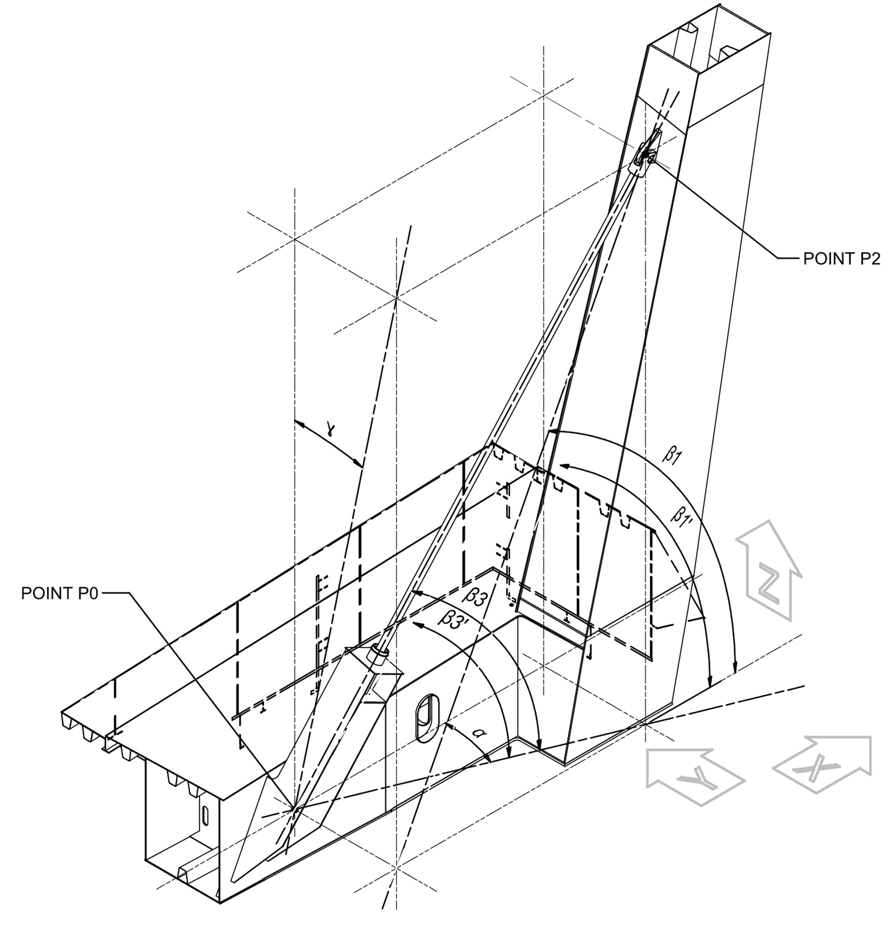
Additionally, the cable-stayed system is longitudinally asymmetric and battered in all three axes, requiring thorough tracking of 24 specific coordinates to ensure that the working points of the stay angles were all coplanar and that the loads of the tie plates were properly balanced. Diagrammatically expressing the coordinates and slopes of each individual stay cable and its supporting elements in 2D was complex (Figure 6).
The use of the 3D design model expedited the precise geometric coordination of the orthotropic deck and cable-stayed systems as well as with other coordinating elements such as the movable joint components and substructure.
The digital twin was also crucial in the development of emergency egress and maintenance personnel access within critical parts of the superstructure. The 3D model was implemented again at this stage to coordinate the superstructure, substructure, and mechanical elements, as well as detail the confined space and material handling of the pivot area (Figure 7).

Swing span delivery
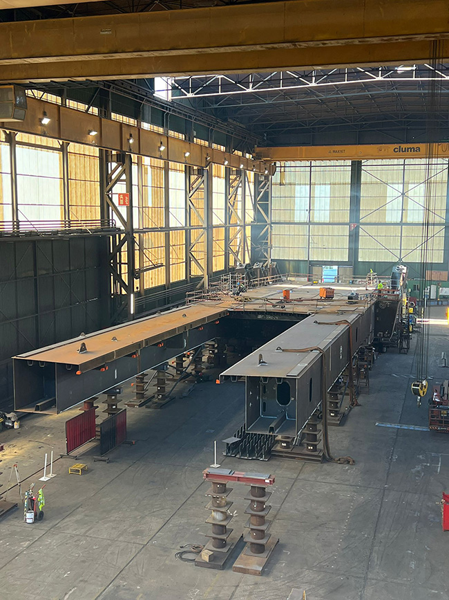
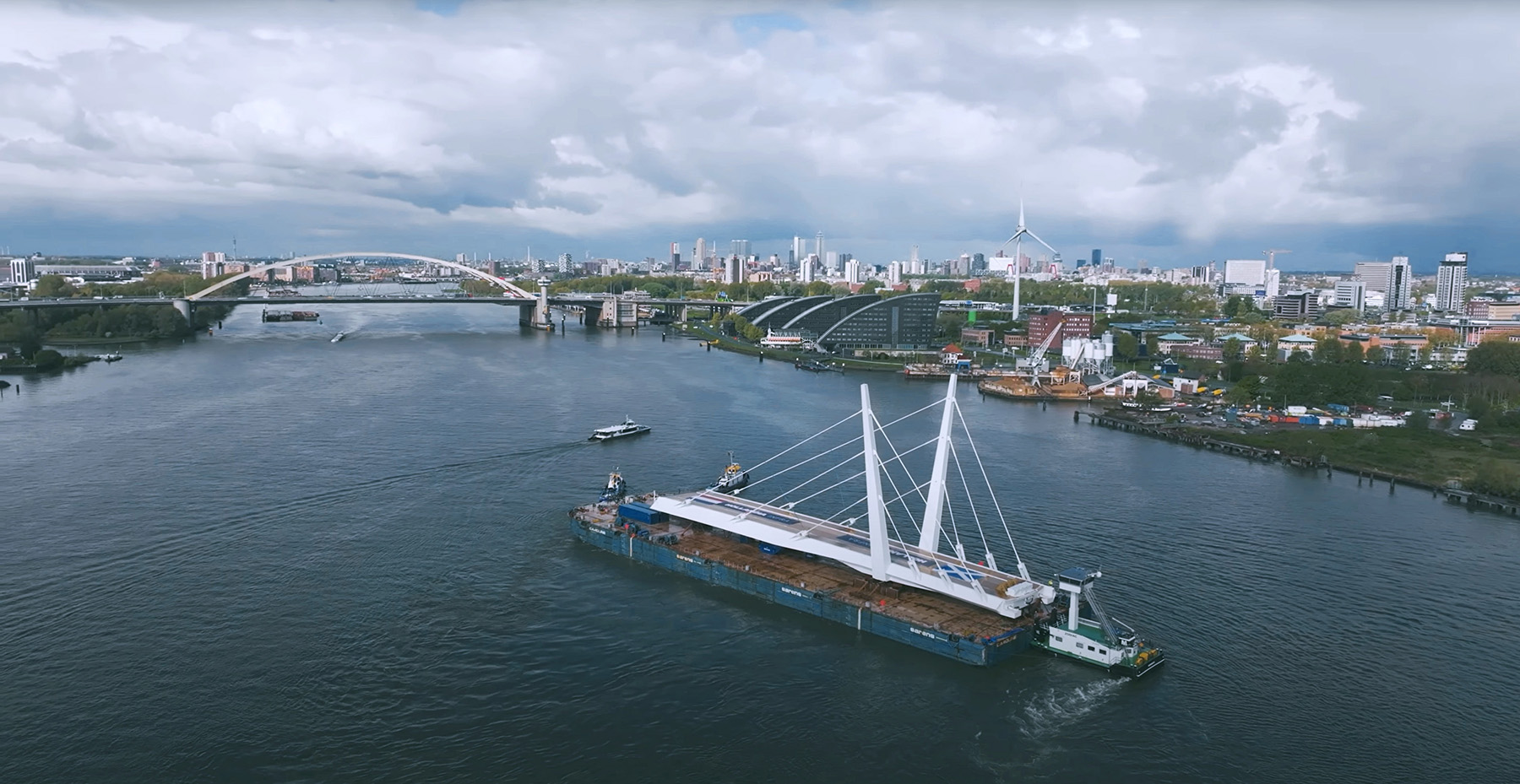
Transporting the swing span leaves in their entirety by self-propelled modular transporters, marine cranes, and barges was another advantage of the lightweight structure. Each leaf was fully fabricated, welded, and assembled at its respective fabrication shop rather than being constructed on-site; this meant the fabrication of each span could progress concurrent to the progress on the jobsite.
Prefabrication eliminated the need for traditional bolted or welded field splices in the superstructure. In addition to structural fabrication, all priming and painting was performed in controlled environments at the shops. Wind fairings were installed, and counterweights were filled with heavyweight concrete and balance blocks prior to transport. Additionally, nearly all mechanical, hydraulic, and electrical components of each leaf were installed, routed, fastened, and tested prior to delivery on-site.
For installation of the cable-stayed system, each stage of cable stressing required a specific deflection in the superstructure before advancing. Dead load at these discrete stages plays a major role in sequencing; therefore, it was advantageous to perform substantial completion of the stressing prior to transporting the structure.
Sixteen of the total 22 stages of cable-stay stressing were conducted in the controlled environment of the fabrication yards. Performing this precise operation on land instead of over the River Clyde expedited the process, giving surveyors flexibility in their setups for deflection control and giving the strand jack operators proper and safe mobility to travel around the leaf without concerns of conflicting with other trades on-site.
Prefabrication planning also had a positive impact on project safety, as the majority of traditional overwater work could be eliminated. Heavy components and subassemblies were lifted and installed on land with factory cranes using the fabricators’ own personnel, who were familiar with the work. Skilled mechanical and electrical installers were able to perform their specialty work in the controlled environment of the shop rather than working in the traditional way: in the temporary and congested environment of the project site.
The 3D models used during the design and fabrication phases evolved into models used in the transportation planning of the project delivery. Engineers responsible for marine transportation were able to use the model for load balancing and shoring of the structure on the barges and self-propelled modular transporters.
Prefabrication of the movable swing spans benefited both project costs and sustainability. This construction method reduced the need for temporary infrastructure such as trailers, diesel generators, and sanitation facilities typically required for bridge projects. By floating in bridge segments from the Netherlands and Belgium, the surrounding region and native ecosystem of the site were less affected by commercial vehicles transporting large components as well as personnel required for the assembly of the bridge.
Moreover, the fully assembled spans were installed on the pivot piers within a short amount of time, significantly limiting the cost of marine cranes and water work.
Conclusion
Overall, efficiency and sustainability were central to the design of the Renfrew Bridge. The specific design decisions of the swing span team resulted in an optimized structural and mechanical arrangement that led to a reduction of materials. What’s more, these design decisions successfully created a lightweight, movable bridge structure. While uncommon, the combination of a cable-stayed swing bridge with a fully welded steel orthotropic deck superstructure substantially lowered the weight of the movable span, providing the structural, mechanical, and construction teams flexibility to choose the most efficient ways to deliver the project.
The development of the design model in 3D enabled multiple stakeholders to leverage modern tools to coordinate their important geometric checks. This workflow facilitated more efficient coordination among all teams, as geometric changes were able to be performed rapidly and instances of rework were minimized. While a higher level of technical proficiency is needed for 3D delivery, it has proved to be an invaluable tool and is becoming standard practice in the industry.
Hollandia Infra and Iemant’s approach of focusing on prefabrication greatly improved the deliverable quality of the bridge superstructure and movable bridge components. The prefabrication process expedited the construction timeline, increased overall project safety, and reduced the carbon impact of the project. It is clear that proper coordination and planning allow for longer-span movable bridges to be designed more economically and efficiently.
James M. Phillips III, P.E., is a principal and the national practice leader for bridge design at H&H.
Barry Keung, P.E., is the digital design director at H&H.
Project credits
Owner
City of Renfrewshire, Scotland
Specimen design
Joint venture of Kettle Collective, London; Cass Hayward, Monmouthshire, UK; SWECO, Leeds, UK; and KGAL, Poole, UK
Lead movable bridge and slewing machinery systems designer
H&H, London
Prime swing span designers
H&H, London, and ROD, Dublin
Design-build
GRAHAM Construction, Glasgow, Scotland
South swing span fabrication, machinery fabrication, and supply (both spans)
Hollandia Infra, Rotterdam, the Netherlands
North swing span fabrication
Iemants, Arendonk, Belgium
This article first appeared in the May/June 2026 issue of Civil Engineering as “Swinging Forward.”

