
By Nathan Cobler, P.E., M.ASCE, Matthew Wallin, P.E., M.ASCE, and Greg Blackburn, P.E.
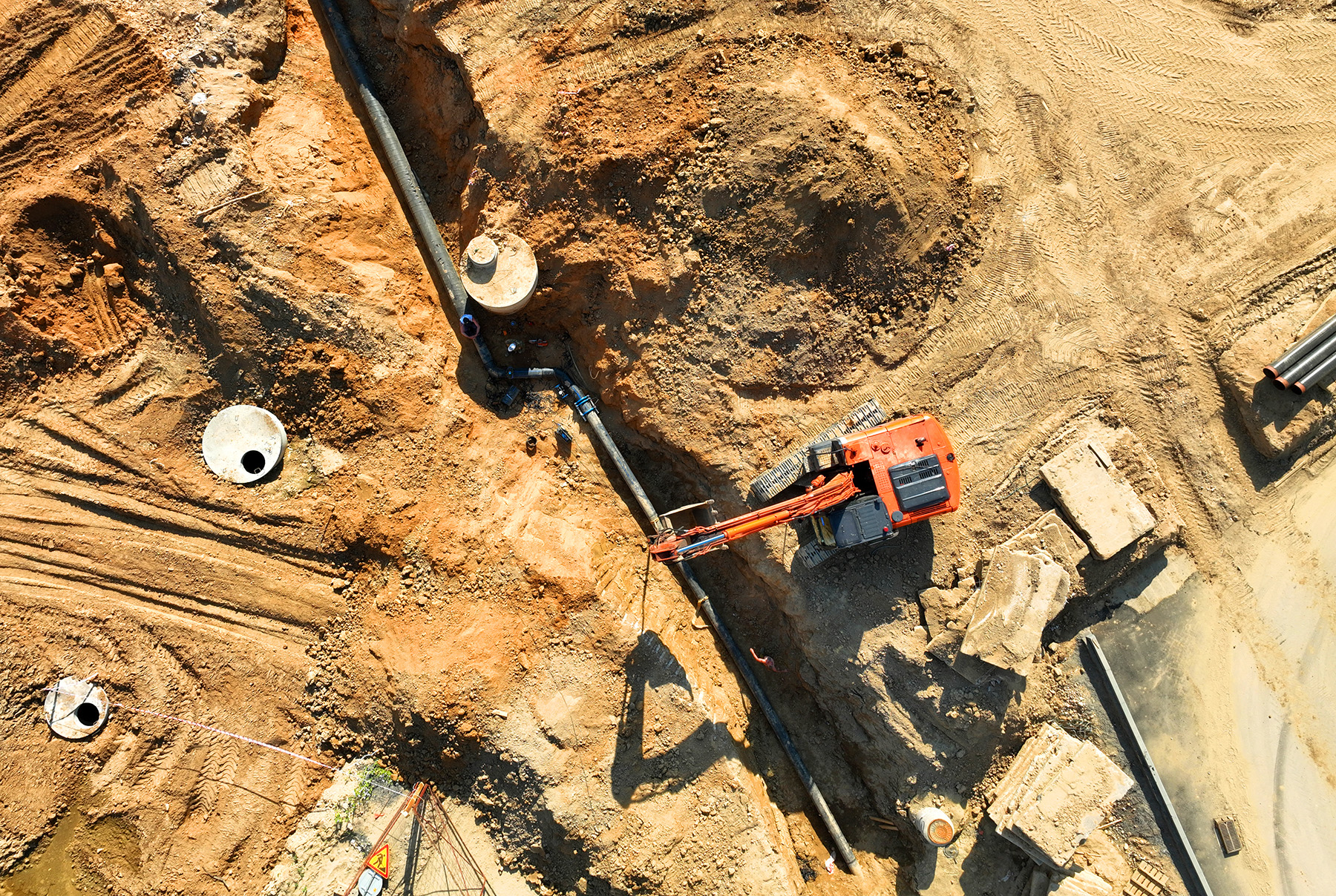
Engineers used creative design strategies, sound geotechnical investigations, and coordinated stakeholder engagement to successfully deliver a complex urban sewer infrastructure project.
The San Antonio Water System W9 Upper Leon Creek Sewer Capacity Storage and Relief Culebra Creek to Whitby Road Project represents a major sanitary sewer improvement initiative designed to address aging infrastructure, increase system capacity, and reduce sanitary sewer overflows.
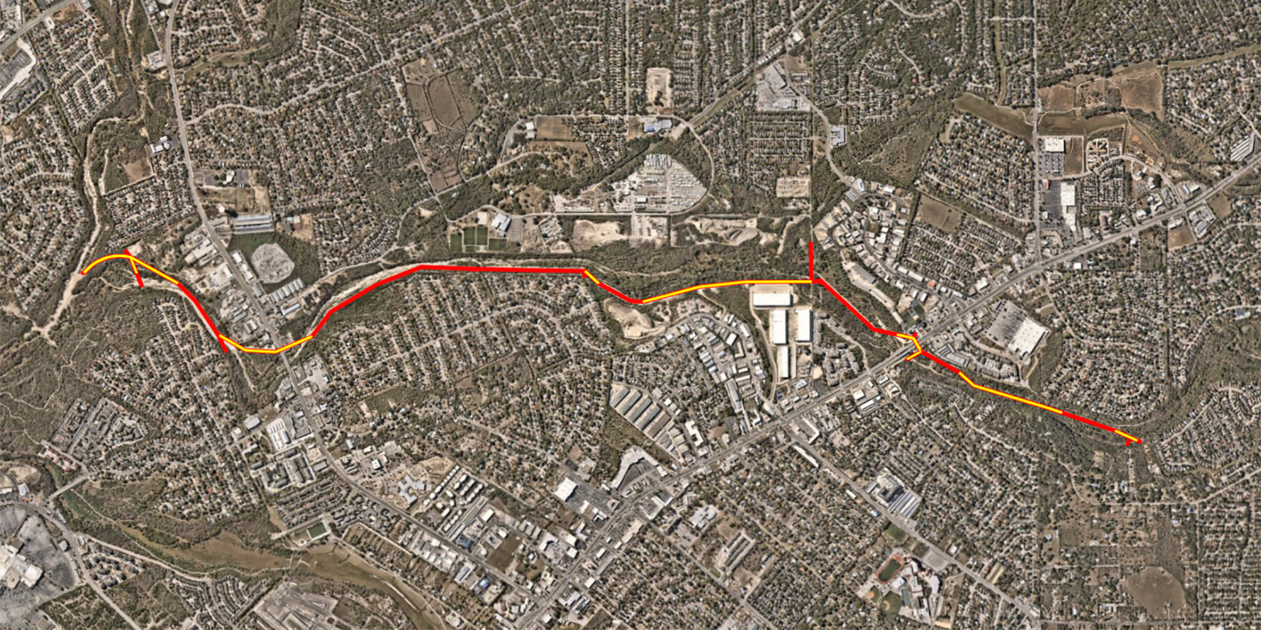
The SAWS W9 project is located within the 100-year floodplain of Upper Leon Creek on San Antonio’s west side. The existing system collects wastewater from the sewer basin and conveys it to the Steven M. Clouse Water Recycling Center on the city’s south side. This ongoing project upgrades the existing 55-year-old undersized sewer system, consisting of 30 in. and 36 in. concrete pipes, and installs a 48 in. fiberglass-reinforced polymer mortar pipe. In total, the new pipeline will stretch 22,000 linear ft with nearly half the alignment constructed through 78 in. diameter tunnel segments. Figure 1 below notes the location of the project alignment, which is identified by open-cut construction segments (red) and tunneled segments (yellow).
Geotechnical investigation and baseline report
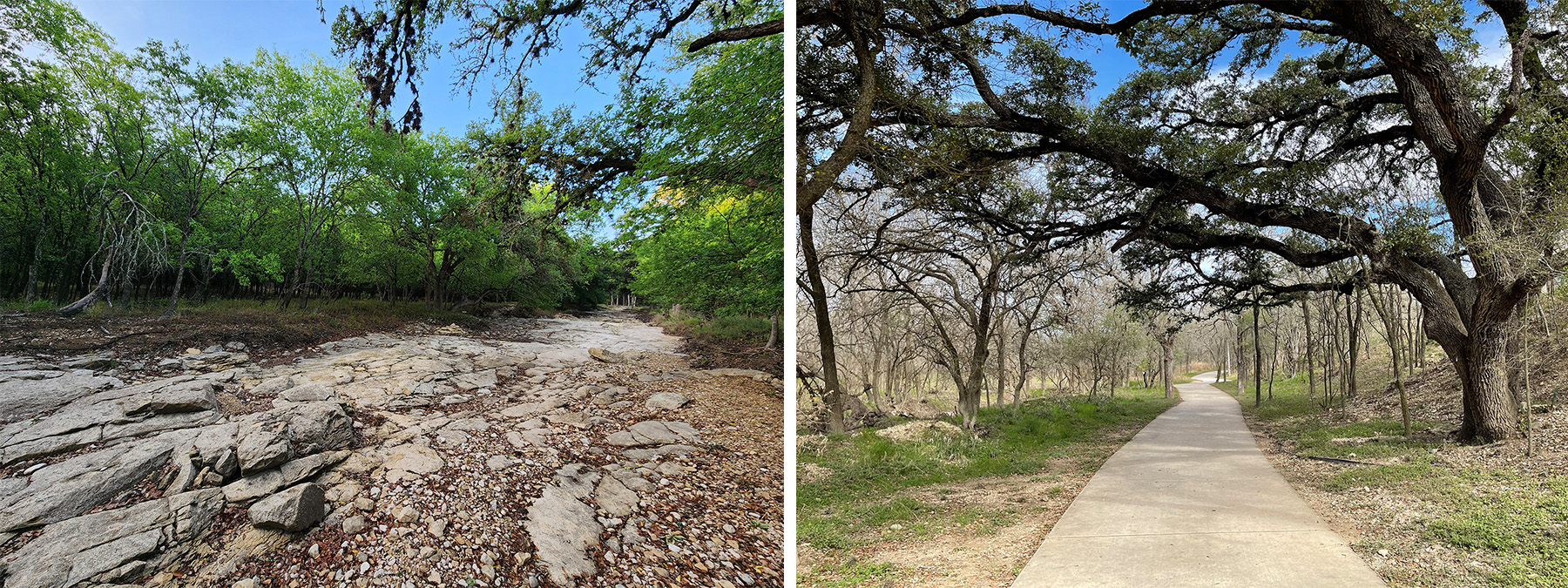
The project corridor traverses property owned by the City of San Antonio Parks & Recreation Department. Above ground, the property is characterized by dense vegetation, numerous mature tree species, and an extensive network of concrete trails. Below ground, the project site spans three types of geological formations: the Austin Chalk Aquifer, Buda Limestone, and the Edwards Aquifer.
Along the pipeline alignment, these three formations presented anticipated conditions of marly limestone and limestone bedrock with associated clayey overburden soils. Between the bedrock and the overlying soils, the engineering properties of the ground span a gradient between very hard/very dense soils and very soft rock.
A geotechnical baseline report was prepared for this project due to the complexity of the design and the subsurface conditions. The report characterized ground conditions based on data collected from two geotechnical investigations, and it provided a baseline definition of the anticipated conditions along the alignment. To visualize these conditions, the design team developed profiles of the baseline subsurface features so that bidding contractors could understand anticipated conditions.
Karst conditions and risk mitigation
The bedrock formations along the project alignment, especially the Austin Chalk Aquifer, allow groundwater to flow through the pores of the rock, gradually eroding the rock and creating cavernous features, known as karsts, that can provide a habitat for endangered karst invertebrates. The challenge with these karsts is that it is impractical to determine their exact locations until they are uncovered during construction.
Environmental surveys identified seven karsts within the Austin Chalk formation along (but not within) the northern portion of the alignment. Although the environmental report listed seven karsts, only two were described in detail, as the others were not deemed potential endangered invertebrate habitats.
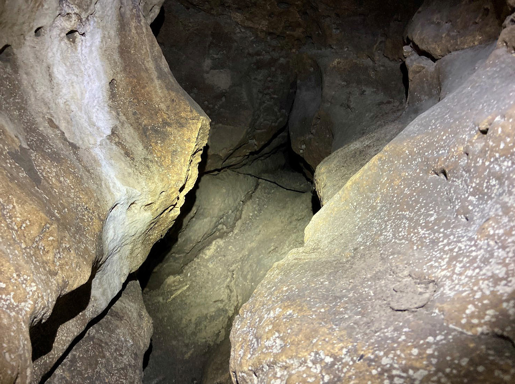
Neither of the geotechnical investigations encountered any caves or karsts larger than one inch in diameter. However, based on the information from the available sources, it is possible that portions of the work will encounter karsts ranging in size from a few inches to many feet.
Because of this, the environmental team was told that any karsts they discovered during construction would need to be investigated to confirm the presence of any endangered karst invertebrates. If their presence is discovered, an action plan developed specifically for this project would be used to mitigate the disturbed area and seal it off from the active construction site, minimizing further impacts to the habitat.
To reduce the potential impacts of encountering karst features, certain types of mechanized tunnel shields — including rotary tunnel-boring machines and gripper shields — were not used on the northern segment of the alignment. The design team determined that encountering a large karst void, particularly at the tunnel invert, could hinder access for remediation and potentially cause shield instability or equipment entrapment. At the time of writing, no karsts have been encountered during construction.
Curved tunnel segment
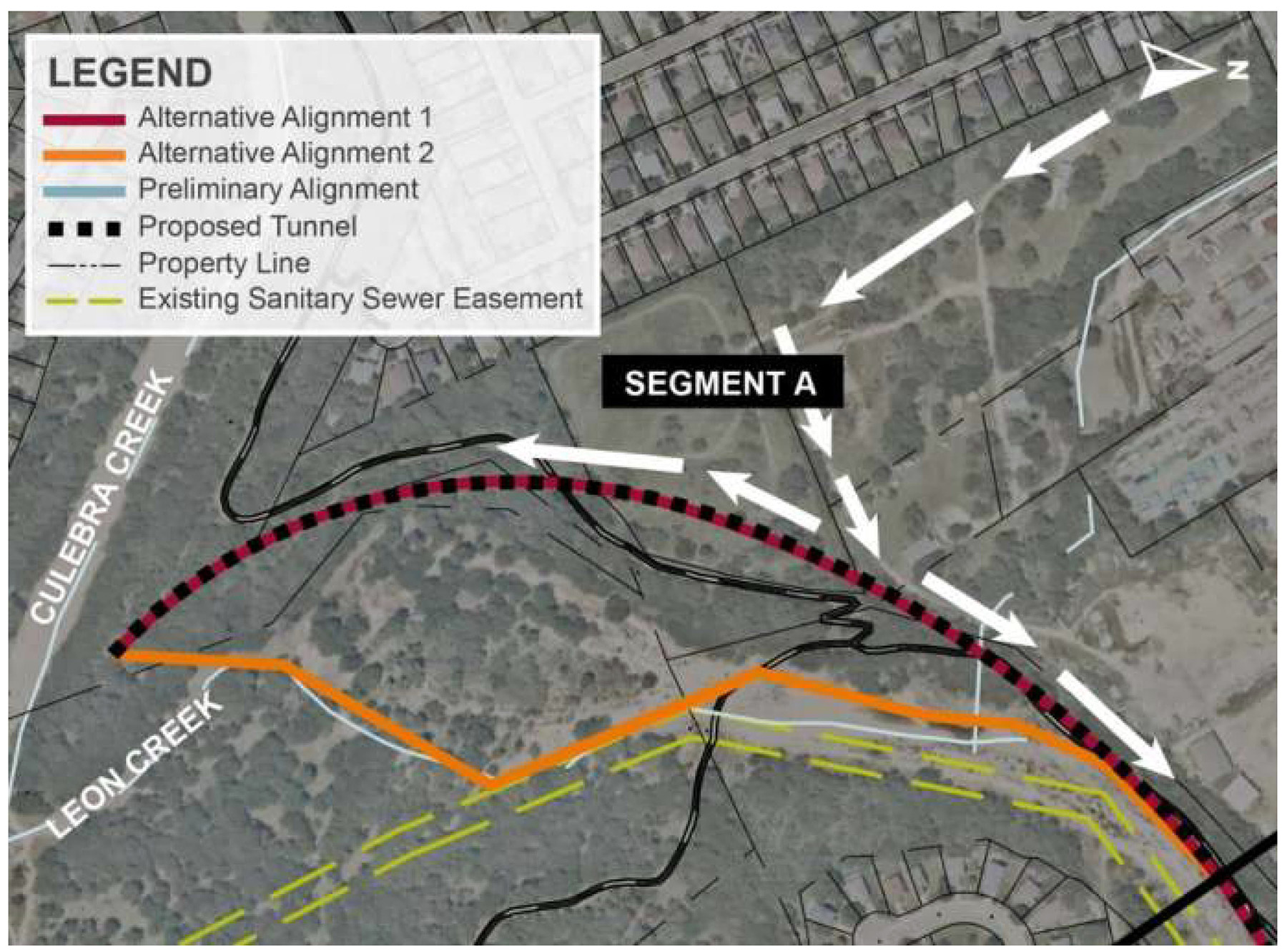
Determining the method of construction for this project was critical to mitigating the numerous challenges faced by the design team, including depth of cover greater than 30 ft, a concrete trail network, mature trees, roadways, and U.S. Army Corps of Engineers-delineated areas where the surface could not be disturbed without performing extensive mitigation methods. One unique aspect of this project is the design of the curved tunnel at the downstream end of the project (Figure 2). Construction of this segment needed to be precise, as it dictated the accuracy of the remaining upstream portion of the project.
During planning and preliminary design, the project team evaluated both conventional open-cut construction and trenchless methods to determine the most appropriate approach. This evaluation focused on constructability, impacts to existing infrastructure and public amenities, safety, environmental considerations, and long-term operability consistent with SAWS and Texas Commission on Environmental Quality standards.
Conventional open-cut construction was initially considered as a viable option for the overall pipeline project; however, maintaining the required hydraulic grade line while avoiding conflicts with existing utilities and adjacent gravity sewer infrastructure would have required excavation depths exceeding 30 ft in several locations. Excavations of this depth would have introduced constructability challenges, including complex shoring systems, extensive dewatering, and potential slope stability concerns given the proximity of the 100-year floodplain and a steep bluff adjacent to portions of the alignment. These conditions would have increased construction risk, duration, and cost, while also elevating safety concerns for construction personnel.
Trenchless methods were evaluated as an alternative approach capable of addressing these challenges. Tunneling would allow the gravity sewer to be installed at a consistent depth independent of surface features and topography, significantly reducing surface disturbance and exposure to floodplain conditions.
Furthermore, tunneling provided a controlled installation environment (for example, discrete launch and retrieval shafts) that reduced reliance on extensive shoring and dewatering while mitigating risks associated with deep excavations. Based on these considerations, the project team decided on tunneling many segments of the pipeline, including the downstream curved segment of the project, which is approximately 1,000 linear ft of the project. Open-cut construction will be the method for the remaining segments.
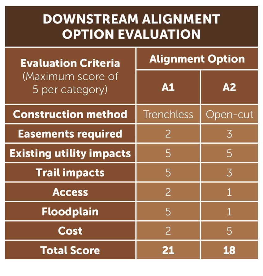
Selection of the installation method for the downstream portion of the gravity sewer was a critical component of the overall project design due to the concentration of physical, environmental, and operational constraints within this portion of the alignment, as shown in the table above.
Following selection of tunneling as the installation method for some segments, the design team evaluated potential tunnel alignments to accommodate the constraints present within the downstream project limits. These constraints included:
- A required tie-in to an adjacent SAWS gravity sewer project that established fixed downstream horizontal and vertical control points.
- Existing gravity mains within the 100-year floodplain.
- Required lateral connections to intercept existing flows.
- Park trails and mature trees.
- Challenging terrain characterized by the steep, curved creek bank rising approximately 40 ft above the existing gravity main.
A curved tunnel alignment paralleling the contours of the bluff provided the flexibility necessary to navigate around critical conflicts while maintaining acceptable hydraulic performance and structural integrity.
By following a curvature compatible with trenchless construction methods and pipe material limitations, the alignment successfully connected the fixed upstream and downstream control points while avoiding existing infrastructure and environmentally sensitive areas.
This approach also allowed lateral connections to be accommodated without introducing adverse hydraulic conditions or excessive structural complexity.
To ensure the design would be constructable, the design team engaged multiple tunneling contractors and suppliers regarding the minimum curvature compatible with various tunneling methods and equipment, as well as carrier pipe materials.
The consensus was that 800 ft was a reasonable radius for tunneled construction for 72 in. to 84 in. diameter rib beams and lagging or steel liner plate supports.
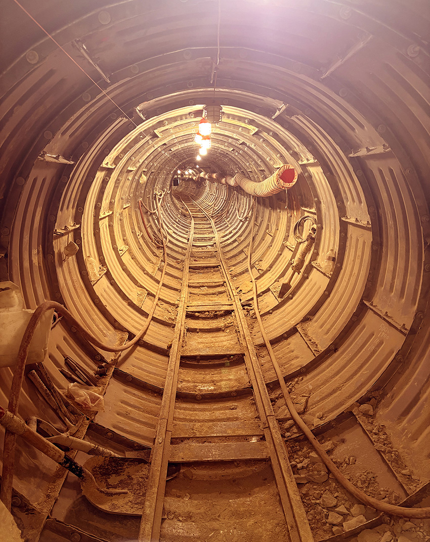
The contractor installed the fiberglass-reinforced polymer carrier pipe in 10 ft lengths within the completed tunnel. This ensured that the pipe segments could be threaded through the completed tunnel and that the deflection at each gasketed joint would not exceed manufacturer-recommended limits.
The photo above shows a portion of the 800 ft radius liner plate tunnel under construction.
Tunnel design and custom specifications
Since more than 40% of the proposed sewer main was to be installed via trenchless construction, the design team developed specifications to clarify expectations, manage risks, and improve constructability beyond what the client’s standard specifications stipulated. By tailoring these specifications, the design team was able to work around the site-specific constraints, reduce ambiguity, help compare bids, and allocate risk effectively to address complex issues. These include dewatering, shaft and tunnel water control, shaft excavation and support, open-face tunneling, portal stabilization, installation of carrier pipe, settlement monitoring, and contact grouting.
Ultimately, such specificity protects infrastructure; minimizes ground movement and water inflow; and helps ensure timely, budget-compliant, and regulation-adhering project delivery.
Due to the diameter and length of the planned trenchless segments and local contractor preference, it was intended that open-face tunneling methods would be used to install the tunnel segments.
Allowable open-face tunneling methods included hand-mining and mechanical excavation such as digger shields or rotary tunnel-boring machines. Hooded shields were allowable for all tunnel segments.
However, due to potential for mixed-face conditions, some high-plasticity materials that could cause clogging of the cutterhead, and the possibility of encountering karst features, use of rotary shields was not allowed in certain locations. The contract documents specified allowable shield types for each tunnel segment.
By adopting this approach, the design team gave contractors clear requirements while also offering flexibility in tunnel excavation. Because tunneling to an exact diameter can be limiting, especially since contractors often own or rent equipment tailored to specific jobs, the team decided to specify a range of acceptable tunnel diameters.
The design team determined that a 48 in. sewer main could be effectively installed within a tunnel excavated to an outside diameter between 72 in. and 84 in. Allowing this range enabled contractors to select construction methods that suited their preferences and available tools, ultimately reducing costs for the client.
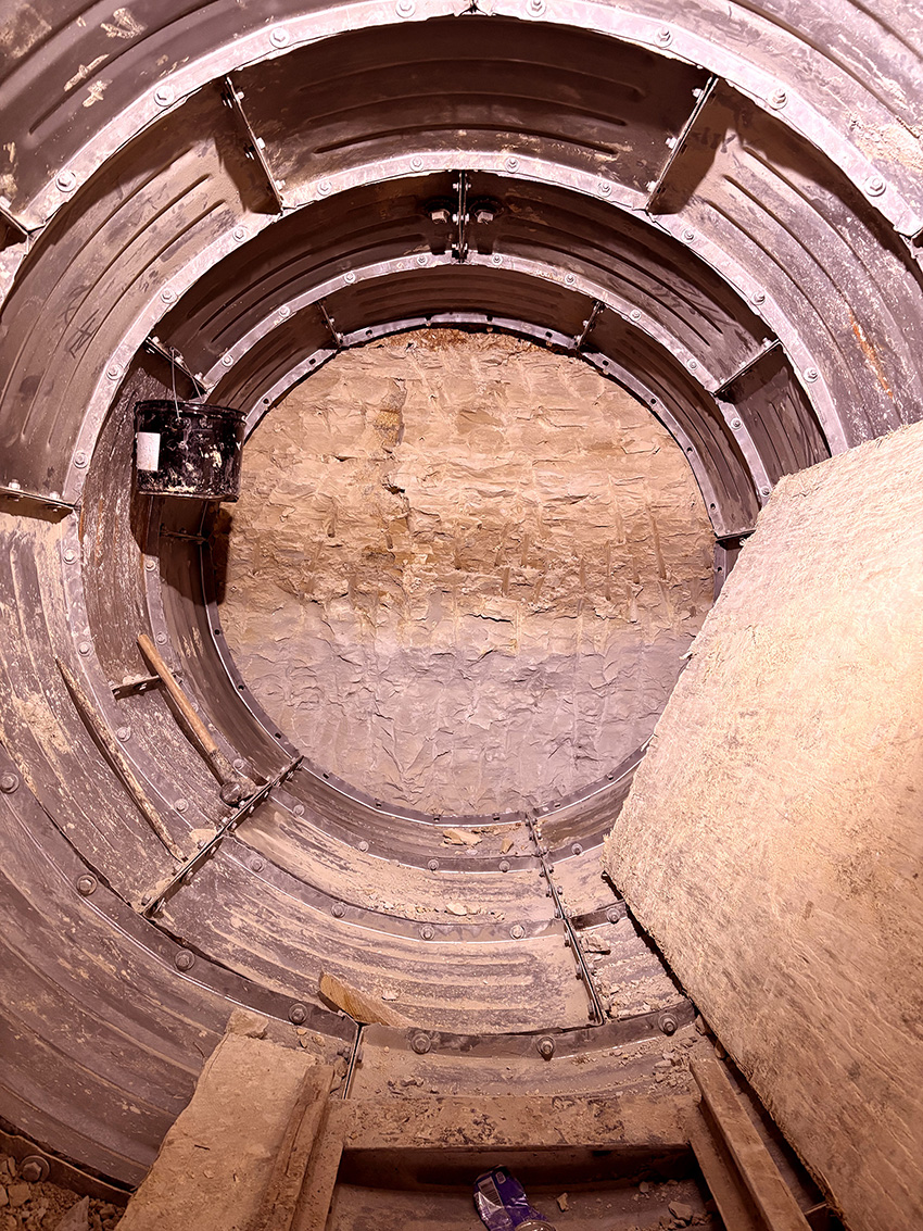
For this project, the contractor opted to hand-mine a tunnel with a 78 in. outside diameter, using four-flanged liner plate for support.
Construction coordination and community access
Securing stakeholder and public buy-in is essential when designing and constructing a pipeline project, as this buy-in can significantly influence the project schedule. Aware of this, the design team committed to meeting regularly with each stakeholder during the design phase to eliminate any confusion about the construction phase. This process included bimonthly check-ins with the city’s parks department and monthly meetings with SAWS.
Among all stakeholders, obtaining agreement from the parks department was vital since the project crossed its property and the proposed alignment would affect the trail network. During meetings with the parks department, the alignment was discussed, and negotiations determined which construction methods would be used to install a replacement sewer main across its property.
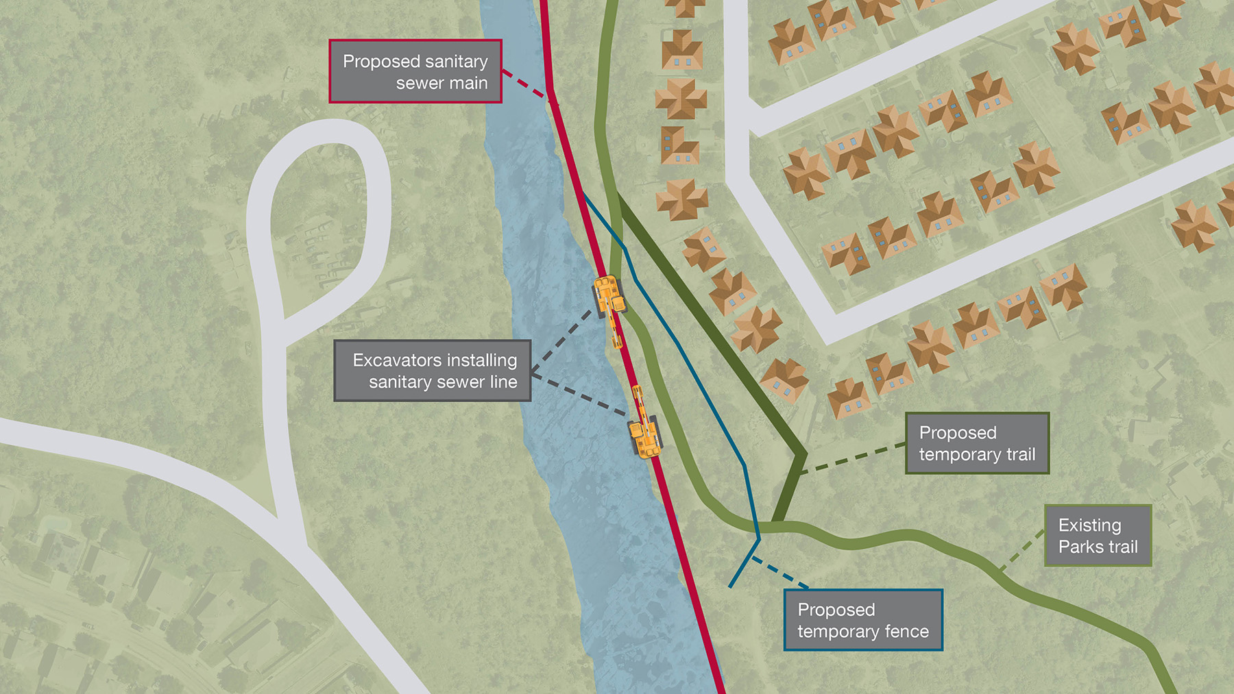
Ultimately, the parks department endorsed the project’s design, recognizing the design team’s genuine efforts to accommodate its needs. The agency required that public access to the parks be maintained during construction. To meet this requirement, the design team built temporary trails, identified where to place construction fencing to keep the public separated from work areas within 200 ft of the trail network, and held four preconstruction public meetings to inform park users about the project and what to expect once construction began. Figure 3 notes an example of one of the alternate trails installed to maintain public access to the trail network.
Conclusion
Key takeaways from this project highlight the critical role of effective communication with both the design team and all stakeholders affected by the project. This includes SAWS and the parks department. The project’s design was significantly shaped by requests from these groups, balancing the need for an expanded sewer system to accommodate increased flows with the necessity of preserving the natural habitat of the land crossed by the new sewer main.
Additionally, the development of customized project specifications proved essential. In particular, allowing contractors flexibility in tunnel diameters enabled prospective bidders to use existing equipment, reducing the need for custom-built or rented machinery. This approach resulted in cost efficiencies for the client.
The SAWS W9 Upper Leon Creek Sewer Capacity Storage and Relief Project demonstrates how thoughtful engineering, geotechnical investigation, and proactive stakeholder collaboration can successfully deliver complex urban infrastructure within an environmentally and socially sensitive corridor. The combination of open-cut and trenchless construction and a curved tunnel alignment enabled the design team to navigate floodplain constraints, karst geology, mature tree preservation, and continuous public access requirements while meeting SAWS and regulatory requirements.
Nathan Cobler, P.E., M.ASCE, is an associate and senior project manager for Kimley-Horn & Associates Inc.
Matthew Wallin, P.E., M.ASCE, is a partner and senior project manager for Bennett Trenchless Engineers.
Greg Blackburn, P.E., is an associate and the Central Texas water/wastewater team lead for HW Lochner.
Project credits
Client
San Antonio Water System
Contractor
SJ Louis Construction of Texas Ltd., San Antonio
Subcontractor
LP Sundance Construction, Ferris, Texas
Geotechnical investigation
Arias & Associates Inc., San Antonio
Rock Engineering & Testing Laboratory Inc., San Antonio
The authors will be presenting this topic at the UESI Pipelines 2026 Conference August 1-5 in Detroit. Find out more at www.pipelinesconference.org.


