By Kyle Sansing, Mark Berns, P.E., M.ASCE, and Erin Querio
The U.S. Army Corps of Engineers has recently finished work on a scour protection project on an existing BNSF Railway bridge, a key piece of infrastructure that crosses the Santa Ana River in Southern California. The new protective features will allow the Corps to increase — when needed — outflows from the upstream Prado Dam without running the risk of washing out the bridge. The project team used creative ways to install these elements, all while protecting adjacent communities, staying on schedule, and keeping rail traffic open at all times.
As one of the final steps in a multidecade program to protect critical infrastructure surrounding the Santa Ana River in Southern California, in September 2017, the U.S. Army Corps of Engineers Los Angeles District awarded the contract for the Santa Ana River Mainstem Lower Santa Ana River Channel, Reach 9 BNSF Railroad Protection project to the joint venture firm MMB, which consisted of Malcolm International LLC, Malcolm Drilling Co. Inc., and BAUER Foundation Corp.
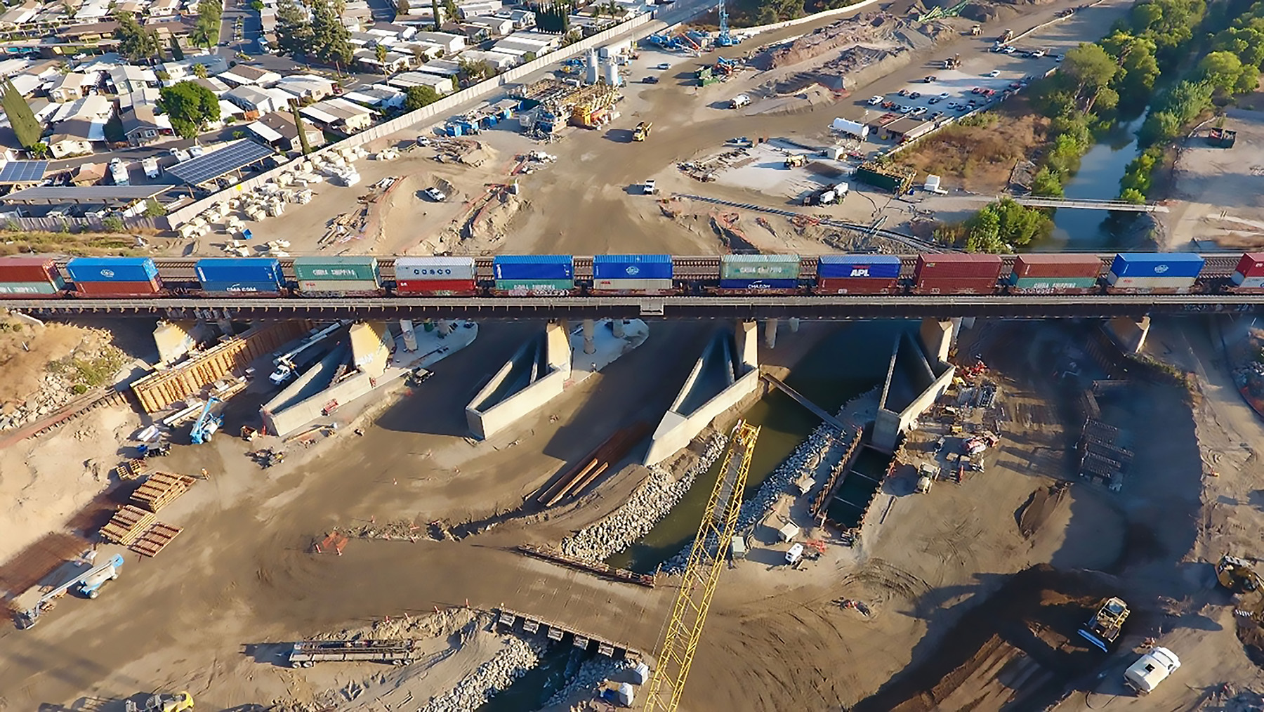
The project involved construction of scour features to protect the BNSF Railway bridge that crosses the Santa Ana River and is 2 mi downstream from Prado Dam in Corona, California. These scour protection features were needed primarily to bolster the flood prevention capabilities of the Corps within the region.
The project’s primary scour protection work consisted of constructing deep foundation reinforced-concrete diaphragm walls, cast-in-place concrete walls, CIP concrete pier noses founded on driven steel H-piles, and grouted and non-grouted armor stone placements.
Ancillary work included improved access to maintenance roads on both sides of the river, above- and below-ground utility relocation work, and associated contour grading and landscaping. The Santa Ana River was rerouted twice to aid phased construction operations at the bridge pier and abutment locations.
A temporary bridge crossing, temporary excavation, and multiple deep cofferdam structures were required to facilitate the work. The project team performed all work operations while maintaining live train traffic because BNSF required that the tracks remain operational at all times. Nearly all the work was conducted in the flood channel in a low headroom condition beneath the BNSF bridge with various time and environmental work restrictions.
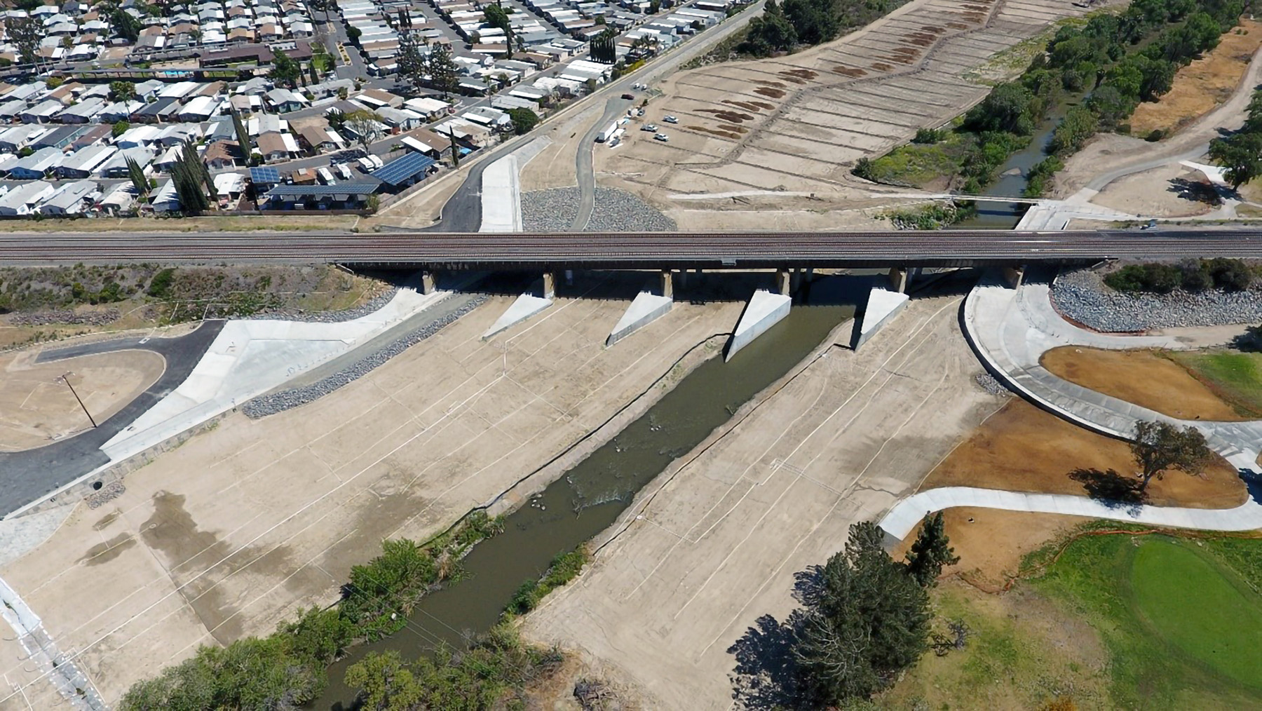
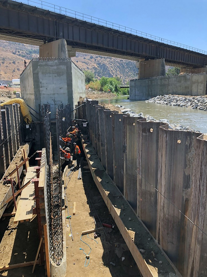
The BNSF bridge, which runs east to west, is technically three separate side-by-side bridge structures. The first of the structures was built in 1938 and is a 654 ft long, seven-span riveted-steel girder bridge supported by reinforced-concrete abutments and piers, all founded on driven steel H-piles.
In 1995, two adjacent structures — both more than 668 ft long — were built and consist of prestressed, precast concrete girders supported on reinforced-concrete abutments and piers, also founded on driven steel H-piles. Each structure supports one railroad track alignment, and all three tracks are owned by BNSF.
A significant amount of commerce uses these rail lines for freight to and from the greater Los Angeles area and the ports of Los Angeles and Long Beach, thereby making this bridge critical infrastructure.
In addition to freight transported by BNSF, regional commuter trains also use the tracks to service the surrounding communities throughout Orange, Los Angeles, Riverside, San Bernardino, and Ventura counties.
River diversion
One major goal of this project was to enable the Corps to increase outflows from the Prado Dam. During the project design phase, it was determined that increasing outflows above current limits of 10,000 cfs would result in a significant risk of detrimental scour at the bridge piers and abutments, culminating in the bridge potentially being washed out. The Corps intends to allow dam discharges of up to 30,000 cfs once all remaining scour protection work is completed along the Santa Ana River.
To mitigate the risk of detrimental scour damage to the railroad bridge, the project team designed reinforced-concrete diaphragm walls to be placed around the bridge foundations. The diaphragm walls were designed to accommodate a minimum of 30 ft of scour below the existing grade, protect the bridge structure, and not impact rail traffic.
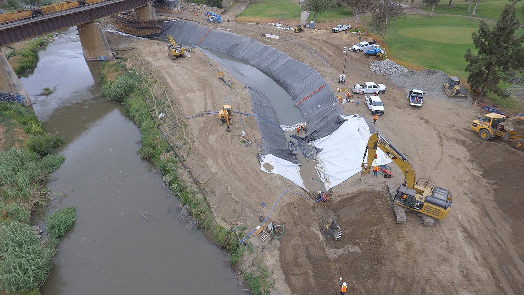
Before construction of the diaphragm walls could commence, about 630 linear ft of the Santa Ana River was temporarily diverted 100 ft to the west to accommodate construction of the pier-protection features beneath the bridge. The diversion, designed by Bittner-Shen Consulting Engineers Inc., was in place for nearly 18 months and had a design capacity of 1,100 cfs.
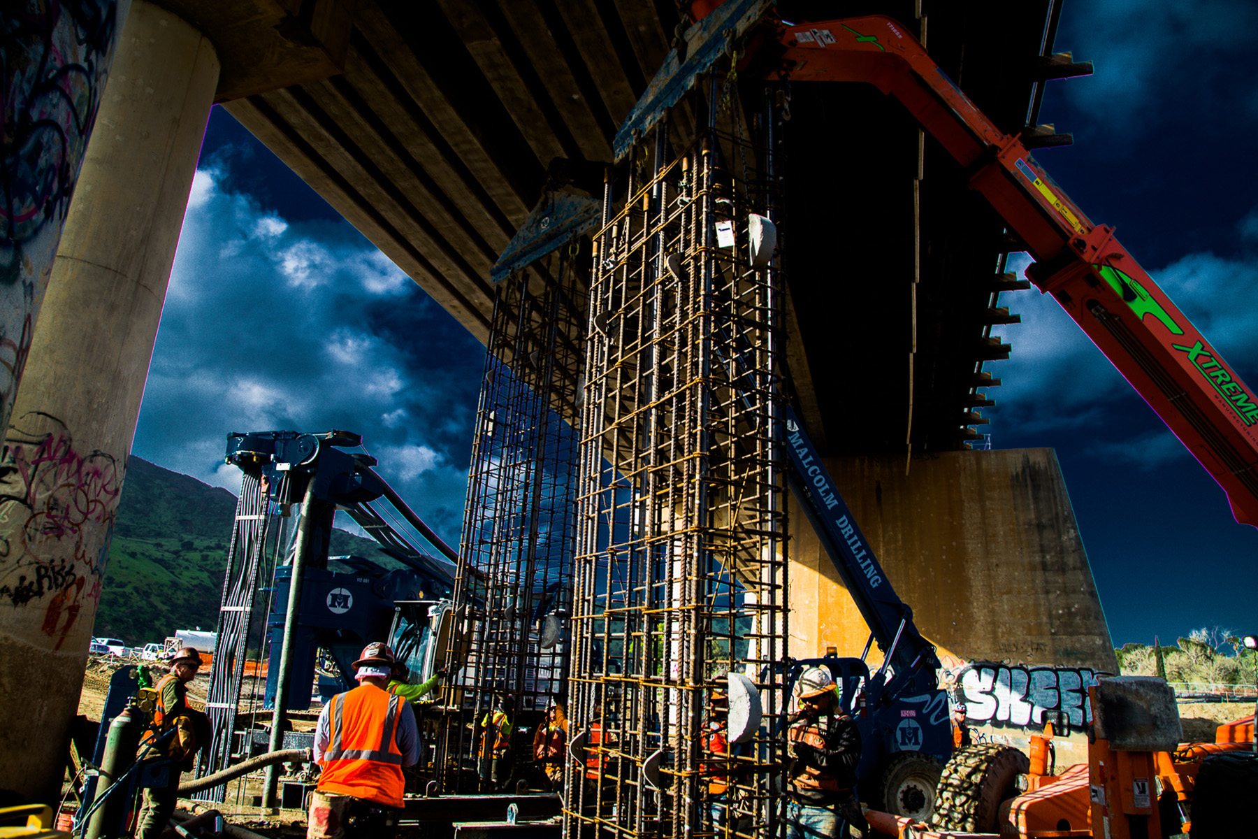
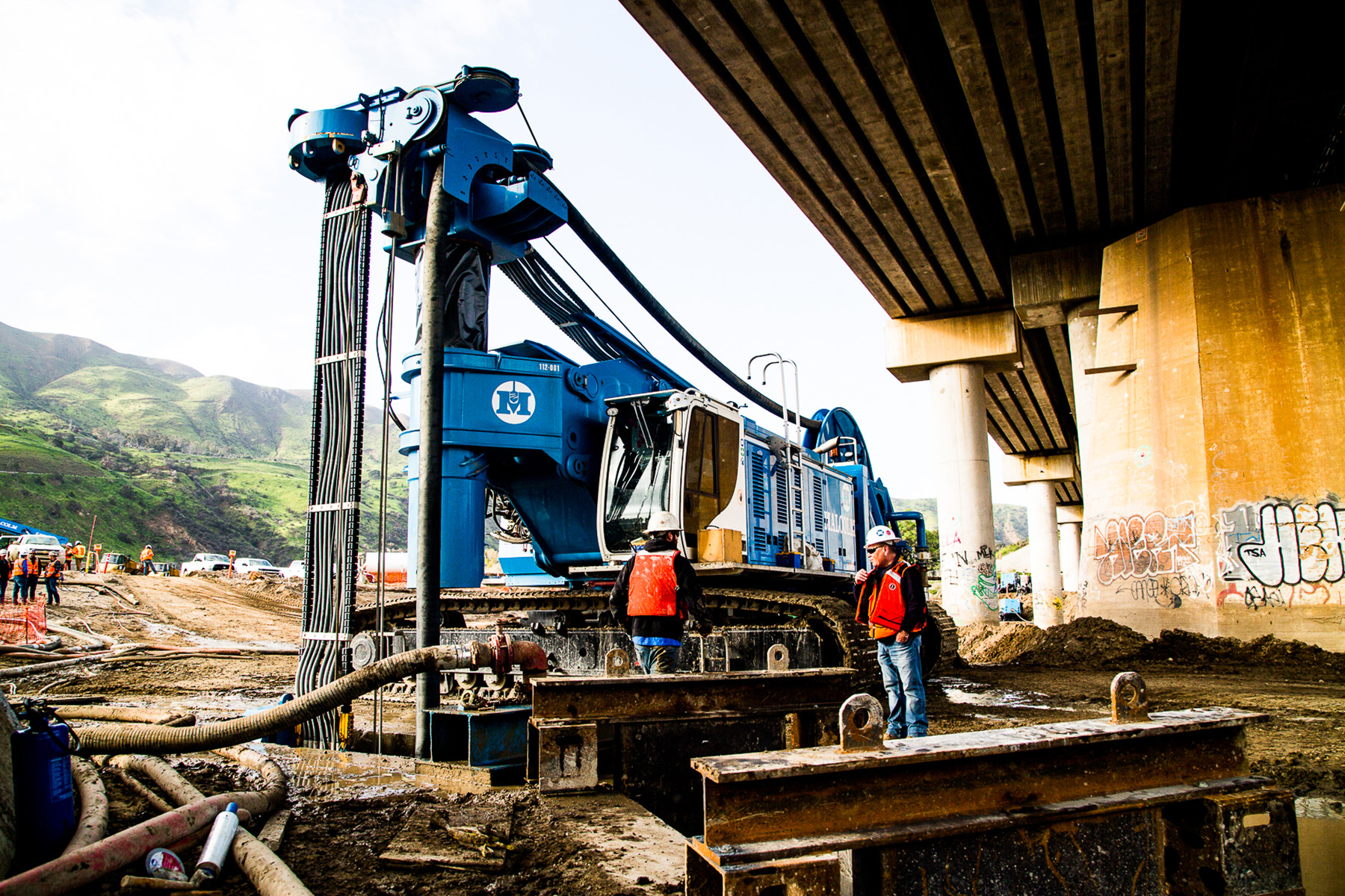
MMB and the Corps collaborated to design the individual diaphragm wall panels. Because some of the panels had to be installed beneath the existing bridge structure, a special low-overhead hydro cutter was used to excavate the ground to make room for the panels.
This same equipment was used for panel excavation outside the bridge structure, but for these panels, the rebar curtains were placed full length without splicing. However, at the time of project bid, there were no low-overhead hydro cutters in North America that could excavate panels of the size indicated in the original design drawings. MMB and the Corps and its design representatives, including AECOM, redesigned the panel sizes so the right equipment could be used for construction of the wall panels.
The deepest diaphragm wall panels were about 95 ft long. Panel sizes varied slightly but were generally 4 ft thick and 9-21 ft wide. Tiebacks were included as part of the diaphragm wall design at each of the abutments, but they could not be installed underneath the footprint of the bridge because they would conflict with the existing bridge abutment foundations.
Instead, reinforced-concrete T-shaped diaphragm wall panels were incorporated into the design where tiebacks could not be installed. These T panels act as cantilever retaining walls. The below-grade portion of the T panels was built as part of the diaphragm wall construction process, while the above-grade sections were constructed as formed CIP concrete walls. Rebar for the diaphragm wall sections was coupled to the rebar needed for the CIP wall sections.
The project soils generally consisted of sandy material with scattered cobbles. During hydro cutter excavation of the diaphragm walls beneath the railroad bridge, the team frequently encountered debris: steel pins, rebar, and timber fragments. It is believed the debris was left over from construction of the original 1938 bridge.
Concrete testing
Project specifications required that cross-hole sonic logging testing, done by GEI Consultants Inc., be executed on all the diaphragm wall panels to verify concrete integrity. The specifications also required that CSL access tube spacing be no more than 6 ft to allow for vertical offset testing if anomalies were detected in the concrete. Therefore, the number of CSL test tubes in each panel varied from four to 12, depending on panel length and shape. The number of CSL test profiles created between the tube pairs ranged from six profiles on the four-tube panels to 26 profiles on the 12-tube panels.
GEI used thin-wall steel tubes for the CSL testing because the panel walls were not the standard thickness. Styrofoam block-outs for permanent tieback anchors and through-wall drain features were expected to affect the CSL test results and possibly cause unacceptable segregation of the concrete during placement or laitance entrapment. Although the block-outs’ presence was apparent in all the CSL profiles that intersected them, there was no evidence of significant or unexpected flaws or inclusions.
Testing all adjacent tube-pair combinations on more than 87,000 linear ft of access tubes generated 3,167 CSL profiles, totaling more than 173,000 linear ft. Minimal anomalies were detected in this statistically significant number of samples.
In addition to CSL testing, GEI conducted panel verticality testing, concrete testing, rebar inspection, and bentonite slurry testing to meet the acceptance criteria on each panel. Panel verticality testing, rebar inspection, and bentonite testing were required prior to concrete placement. Additionally, GEI carried out CSL testing and concrete strength testing for final panel acceptance.
As diaphragm wall construction was completed at each of the bridge pier groups, CIP-reinforced-concrete nose and cap structures were built to complete the scour protection for those piers. A portion of the diaphragm wall cap structure consisted of a 3 ft thick slab-on-grade, while the remaining cap area consisted of a 2 ft thick training wall with a 1 ft thick training wall soffit slab cap.
The training walls placed on the upstream (north) side of the bridge featured a pier nose and tapered shape with a rounded edge to accommodate hydraulic flow and allow water to easily pass between pier groups.
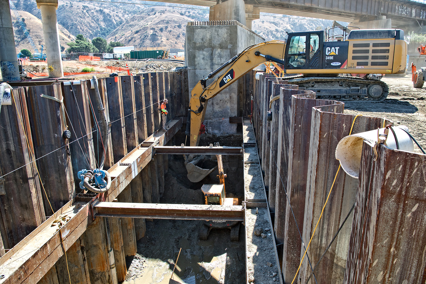
The CIP pier noses and footings were constructed on top of driven steel H-piles. The bottoms of the pier noses were nearly 40 ft below grade. Construction of the pier noses occurred inside braced sheet pile cofferdams, designed by Bittner-Shen. Continuous dewatering wells and localized unwatering were needed for the cofferdams because of the adjacent river and the highly permeable sandy soils in the area.
Anchor design
The project specifications required the design and installation of permanent tieback anchors along the east and west abutments. MMB developed the anchor design using design loads provided in the contract documents, and the locations for 117 anchors were based on the final approved diaphragm wall panel layout. Due to specification requirements and soil conditions, MMB used full-length, 8 in. temporary casings for anchor installation using a Klemm 806 drill rig. Since the anchors were specified for permanent use, double-corrosion strands protected by high-density polyethylene sheathing were applied, and anchor heads were embedded into the diaphragm wall using non-shrink grout.
To ensure the anchor bond zones occurred in the correct soil strata, MMB installed anchors at angles between 15 and 55 degrees. Based on design loads up to 450 kips and test loads up to 600 kips, MMB installed anchors up to 106 ft long with up to 13 strands at the east abutment. Based on design loads up to 410 kips and test loads up to 550 kips, MMB installed anchors up to 97 ft long with up to 12 strands at the west abutment.
The tieback anchors were backfilled with 4,000 psi cement grout prior to conducting performance or proof testing. All anchors were successfully tested to 133% of the design load and locked off accordingly. Cells were installed on 11 anchors so their loads could be monitored monthly for optimal system performance following project completion. In the long term, because access has been maintained, the permanent anchors with load cells can be monitored at any time for as long as necessary.
Upon completion of tieback installation in the diaphragm walls at the east abutment, MMB excavated to depths of 35 ft to install two types of stone scour protection: grouted and derrick. The grouted stone gradation requirement was akin to a typical 24 in. riprap. Grouted stone was placed on slopes with steepness as great as 2H:1V.
After excavation was complete, the stone was carefully placed to the indicated depths and subsequently grouted with a 2,500 psi grout mix. After the lower sections of grouted stone were installed, 48 in. (maximum diameter) derrick stone was placed to further protect the base of the grouted stone. All derrick stone and a portion of the grouted stone were buried to restore the grades within those areas of the river channel.
The grouted and derrick stone scour protection provided an important link that extended the east abutment scour protection from the newly constructed diaphragm walls to a preexisting grouted stone and derrick stone placement located north and south of the bridge. The west abutment did not require derrick stone, and minimal amounts of grouted stone were used.
Dewatering the site
Diaphragm wall construction, temporary river diversion, and excavation activities for grouted and derrick stone placements all required dewatering of the surrounding site soils. The dewatering system was designed by Middour Consulting LLC. In total, 63 dewatering wells and 11 observation wells were needed to accommodate construction activities. Ten of the dewatering wells were 4 in. in diameter and the remaining ones were 12 in. in diameter. Water captured from the dewatering wells was piped to nearby holding tanks to test its quality and allow sediments to settle before being discharged into the adjacent river.
Combined dewatering discharge flows were generally around 3,000 gpm, with maximum flows near 6,000 gpm, due in large part to the pervious, sandy soils found throughout the project and the close proximity of the Santa Ana River.
In addition to the various scour protection features previously discussed, MMB was also responsible for several ancillary features, including the paving of multiple access roads and maintenance roads throughout the project. In total, more than 3,000 linear ft of 4 in. depth hot-mix asphalt pavement and more than 700 linear ft of 12 in. depth reinforced-concrete pavement were placed.
A careful balance
This complex project had many stakeholders, the most critical being BNSF Railway, whose tracks ran through the center of the project. The tracks carry more than 100 trains per day, and train traffic could not be stopped at any time during construction. A BNSF flagger was on-site and maintained radio communications with all oncoming trains during the entirety of diaphragm wall construction and other work operations. Reduced train speeds were sometimes required, and some construction operations classified as high risk by BNSF were temporarily delayed when trains were approaching and passing through the project limits.
MMB also coordinated with Prado Dam operators not only to regulate dam outflows to accommodate upstream and downstream flooding concerns but also to regulate its outflows because the Santa Ana River supplies the drinking water for downstream communities. Although MMB could have requested reduced flows to make room for some construction activities, the operators always maintained the right to modify flows.
Utility relocation
As with many large infrastructure projects, utility relocation was one of the issues encountered before and during construction. The project was scheduled to be completed within three years. A delay in the relocation of a major fiber optic utility running beneath the project threatened to hold up the start of earthwork operations by a year. However, MMB, along with other stakeholders, re-sequenced work activities to reach substantial completion within the original contract time frame.
Substantial completion occurred in spring 2021, and a contract-required, one-year plant establishment period for landscaping is still underway as of this writing.
Other important stakeholders included Green River Golf Course, located on the western edge of the site, and two housing communities, which are along the eastern edge. Precise and regular communication among all stakeholders were key elements in the successful completion of the project.
Although the project had many complexities, the team was able to work together and rise above the challenges to support the Corps and deliver vital bridge protection and flood control to the region for many years to come.
In April, the project received the ASCE Orange County Branch’s 2021 Outstanding Geotechnical Project Award.
Kyle Sansing is vice president of the Southeast District for Malcolm Drilling Inc., in Pompano Beach, Florida. His LinkedIn profile is linkedin.com/in/ksansing. Mark Berns, P.E., M.ASCE, is an engineering consultant for Berns Infrastructure Inc., in the Milwaukee office. Erin Querio is the director of business development for Malcolm International LLC, in Rancho Cordova, California. Her LinkedIn profile is linkedin.com/in/erin-querio-ba301267.
Project Credits
Client: U.S. Army Corps of Engineers Los Angeles District, Los Angeles
Owners: BNSF Railway, Fort Worth, Texas; County of Riverside, California
General contractor: MMB, a joint venture of Malcolm International LLC, Rancho Cordova, California; Malcolm Drilling Co. Inc., San Francisco; and BAUER Foundation Corp., Odessa, Florida
Civil/earthwork design: AECOM, Los Angeles
Structural/concrete design: U.S. Army Corps of Engineers Los Angeles District
Cross-hole sonic logging and other testing: GEI Consultants Inc., Washington, D.C.
Sheet pile cofferdam design and diversion design: Bittner-Shen Consulting Engineers Inc., Portland, Oregon
Dewatering: Middour Consulting LLC, Woodinville, Washington
This article first appeared in the July/August 2022 issue of Civil Engineering as “Scour Power Protections.”