By Lynda Kiejko, P.Eng., M.ASCE
Despite delays from the curing process, concrete has long been critical in the construction of foundations for electrical system infrastructure. But steel piles are growing in popularity thanks to several benefits.
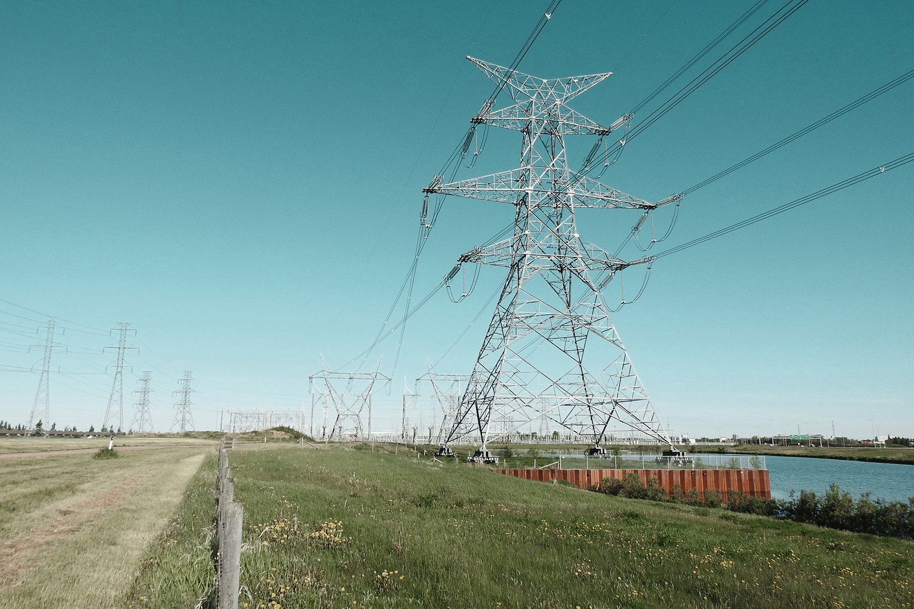
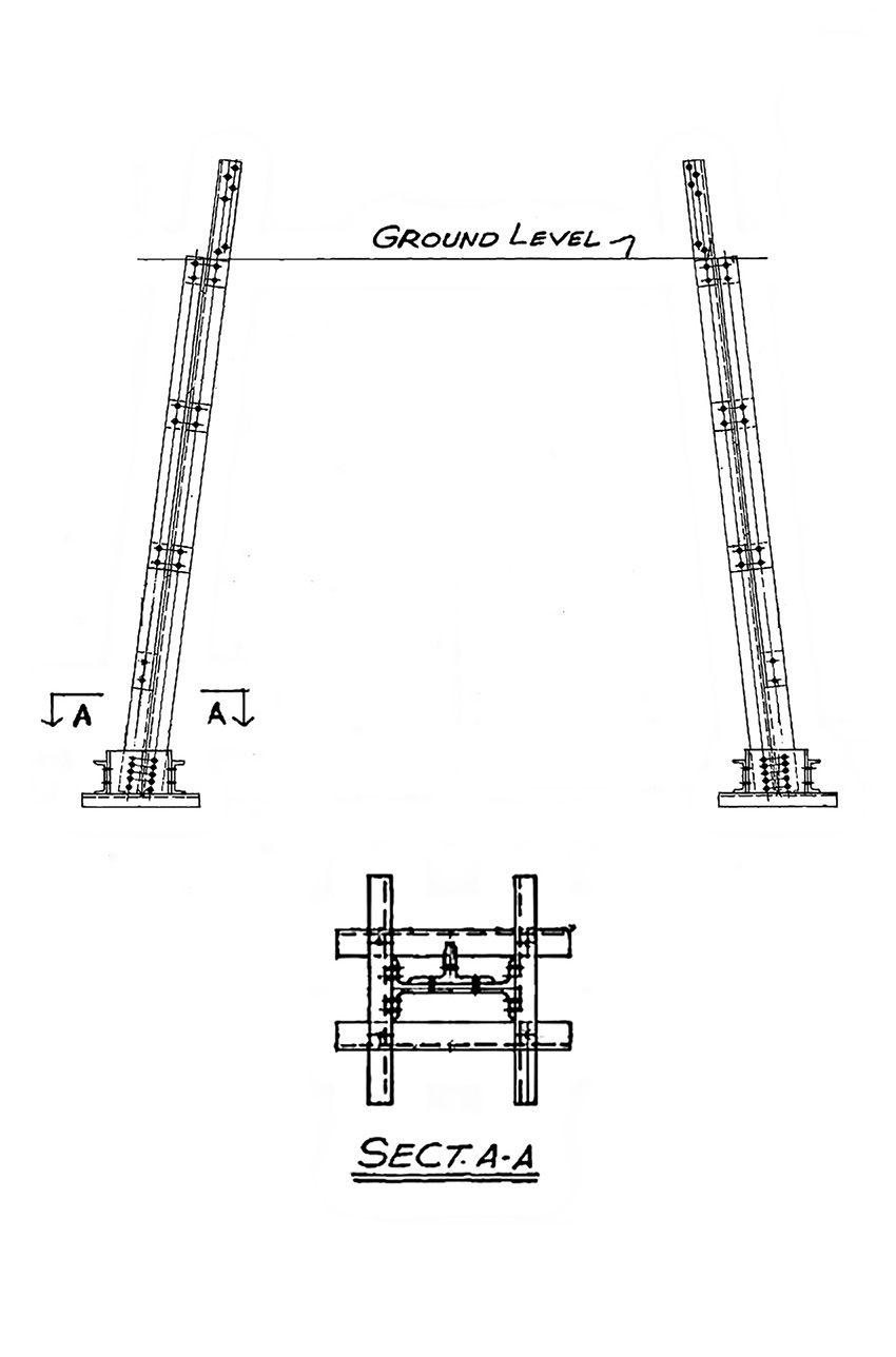
In the electrical transmission industry, using concrete for the foundations of lattice tower transmission lines and substations is a key concern for project schedules. In regard to the towers themselves, grillage foundations encased in concrete have long been a popular solution.
These are, in essence, extensions of the tower’s legs that are placed in a large excavated hole and connected to a steel frame to form a spread footing. The footing is encased in concrete, and then the hole and the grillage are buried in soil up to the base of the tower leg. Where the soils are not suitable for a large excavation, concrete piles are often used instead of the grillage.
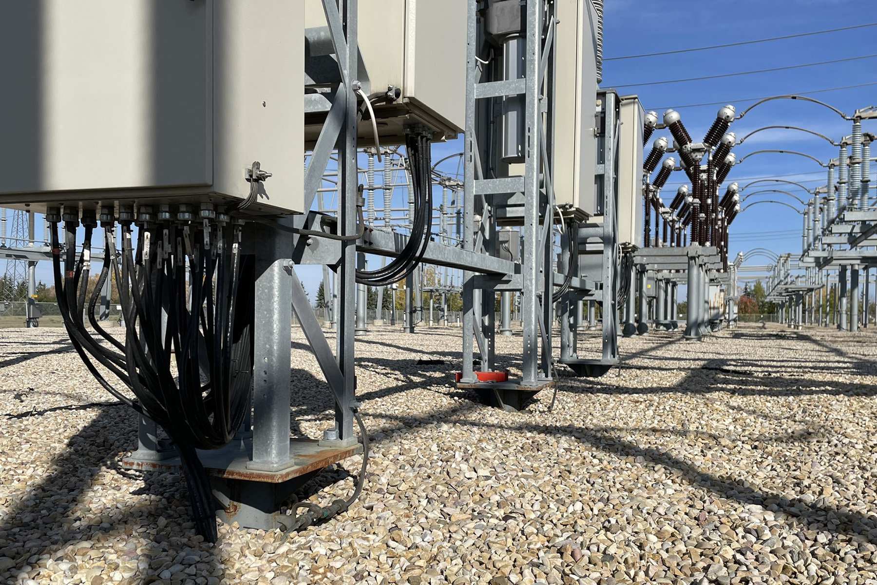
For substations, the heavy equipment within them generally requires a foundation of concrete piles, spread footings, and concrete pads, depending on the equipment type and soil composition.
The problem with concrete, however, is that it must be adequately cured before any loads can be applied, which automatically builds in a construction delay of up to a month. Consequently, engineers are looking for options to reduce the time for foundation installation.
In recent decades, steel piles have been employed more often as replacements for concrete foundations. With several options to choose from and no curing time, steel piles can be a highly effective option to reduce construction timelines. For example, driven steel piles are widely used because of their straightforward design using skin friction and bearing capacity. Screw-shaped helical piles are also growing in demand and availability, though they do require a detailed design by the manufacturer, which can impact delivery and installation.
Steel piles are especially useful in situations in which excavations pose a challenge due to poor soil conditions. Helical piles, in particular, are good in wet or soft soil conditions where excavating a hole could result in significant sloughing.
Although lateral loading of steel piles can be a challenge, one solution is to use battered piles installed at an angle to provide the necessary lateral capacity. But be sure that the foundation cap plate has the capacity to transfer the tower reactions through the pile group accordingly.
Resolving problems with steel
At AltaLink, we are quite familiar with the advantages of using steel in challenging terrain. The company is a regulated electricity transmission provider in Alberta, Canada, that maintains more than 13,400 km of transmission line and 310 substations.
At one of these sites, a double dead-end tower — a structure with line terminations coming in on both sides of the tower and thus typically having the highest foundation line reactions of all tower types — had to be constructed in a wet, environmentally sensitive area that had poor soil capacity but significant loading because of its proximity to a nearby substation.
The use of steel helical piles here provided the necessary strength in terms of soil stability and loading to transfer the load from the tower to the foundations.
In addition, engineers designed and installed a steel sheet wall to create a partial island for the tower to reside on, ensuring that the soil remained stable and the foundation performed as designed.
Because the soil in this area was saturated, eight piles beneath each leg — connected through a 4.5 m by 3.0 m steel beam pile cap that would transfer the loads from the tower to the foundation — were required to meet the design loads.
The design loads (not including an overload factor) were 3,855 kN of compression, 2,098 kN of uplift, and 1,753 kN of horizontal force. The top 3 m of soil featured clay till, the next 3 m were clay, and then clay till was found below a depth of 6 m. The maximum vertical settlement or deflection was designed to be 25 mm.
Considering the complexity of the soil and loading requirements, a traditional steel plate tower shoe could not transfer the loads adequately from the tower into the foundation. Instead, the design team created a unique multilevel pile cap made of steel with many gusset plates.
Typically, a tower leg will rely on one small pile cap for each pile group of roughly three or four piles. But this structure required a much larger pile group of eight piles beneath each leg, which meant a single steel plate welded to the tower shoe would not suffice.
Instead, the team designed a pile cap that featured a steel frame connecting all the piles in the pile group, which were welded together with another steel frame on top to link into the tower shoe. The result was a novel combination of steel construction tying all the piles together.
If the project had used concrete piles in this area, the wet conditions, sloughing soil, and issues with curing the concrete would have required either a casing for the piles or a high-pressure grout to displace the water while installing the foundations.
Regardless of whether concrete or steel was used, some form of erosion protection was required. This was the job of the sheet pile wall, which proved an effective solution for shoring up the soil around the foundation. Because of the steel helical piles, there were no delays for curing concrete or grout and no long-term concerns over possible improper curing. In addition, as soon as the welding was completed, the steel tower was set immediately, significantly reducing construction time in this very challenging location.
Building with buckets
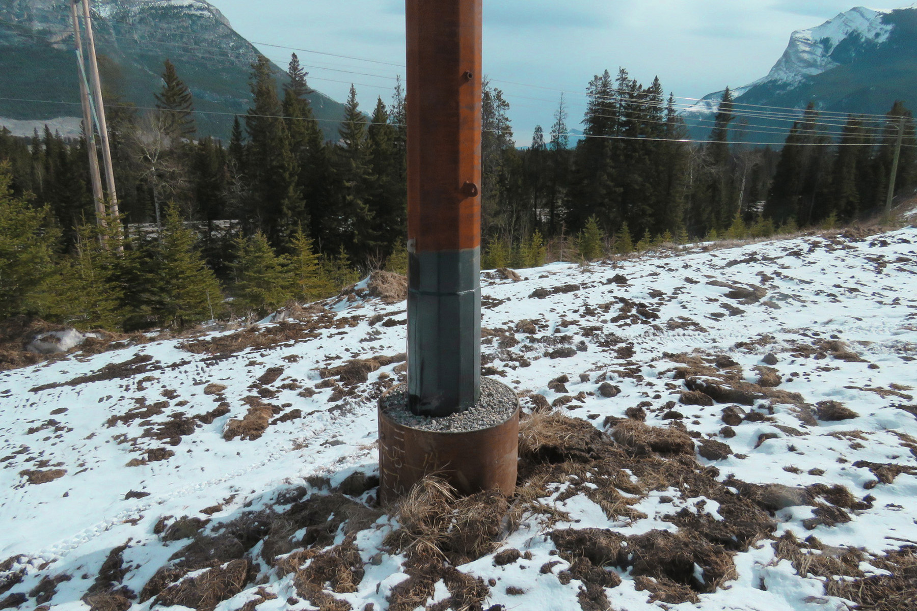
Steel piles can also reinforce the foundations on a wood pole line, especially by employing bucket piles for direct-embed structures. For direct-embed structures, the typical rule of thumb is to bury the bottom of the pole 10% plus 2 ft of the total pole height (for a 90 ft pole, a hole would be dug to 11 ft, and then the hole would be backfilled and compacted around the pole). When that approach is not sufficient, the general practice has long been to erect the pole inside a culvert to provide a larger surface area around the pole while providing a sterile environment within the culvert to use something such as washed rock as backfill.
Washed rock is typically used when there is a barrier to prevent fine particulates from surrounding the soil to fill the voids in the washed rock. It typically locks itself in place and drains well. The culvert increases the surface area around the pole, making the overall structure stable in its long-term performance.
A steel bucket pile offers several benefits over the culvert approach, including limited soil displacement and a reduced need for additional compaction outside the bucket pile. A bucket pile has a larger-diameter cylinder attached to the top of a smaller-diameter helical pile. The pole will eventually be set inside the bucket.
Using a bucket pile allows construction crews to continue with the 10% + 2 ft method of direct embedment for wood structures, creating an engineered foundation that has significantly more capacity with considerably less ground disturbance compared with a culvert installation. The smaller-shaft helical pile pulls the bucket into the ground, which increases the lateral capacity of the aboveground structure’s foundation. The bucket can then be backfilled with little or no intrusion of fines from the surrounding soil due to the steel barrier.
When a bucket pile is used, a guide hole may be required depending on the soil conditions to ensure that the pile can be installed without hitting any obstacles before the desired bucket depth is reached. Bucket piles can also increase the lateral strength of steel pole foundations without changing the overall structural design of the line.
Contending with corrosion
Although steel foundations are susceptible to corrosion, protective coatings — such as galvanization, zinc paint, or proprietary coatings — can mitigate this problem. But be careful not to damage the coatings during installation, and be ready to apply coating patches when necessary. Increasing the overall thickness of the pile during the design to account for the effects of corrosion will help ensure that the capacity of the foundation system does not degrade.
This is a method typically employed in highly corrosive soils and can be used in conjunction with other corrosion mitigations. A bucket pile could be used in place of the traditional culvert. Electrical downleads from transmission structures (the wiring to ensure that there is an electrical path to ground) can also be tied into the steel foundations to ensure the electrical path is effectively maintained. Without this intended path, damage can occur to the structure during an electrical fault.
Expanding solutions
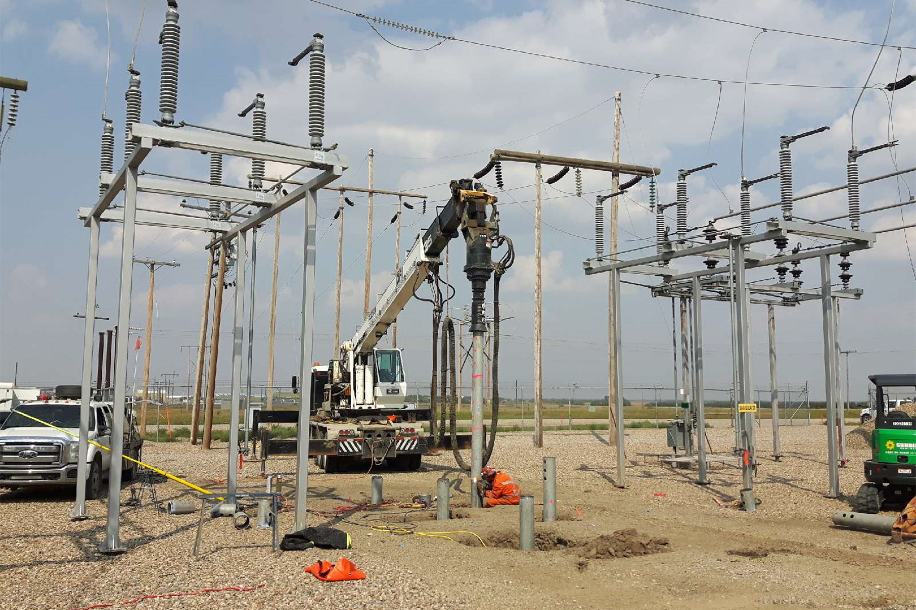
When substations need to be expanded, steel piles are an effective solution for the new foundations. Steel piles cause minimal disturbance to the existing infrastructure. But there are issues to consider, such as the vibration and potential impact on sensitive relays caused by driving steel piles. While driven piles can be installed in brownfield situations without negatively affecting the existing equipment, it may be necessary to carefully monitor the installation of such piles during construction to ensure that the electrical system is not damaged. If the construction activities are extensive, it may also be necessary to remove and replace insulating gravel due to contamination caused by the subsurface material.
Still, AltaLink’s experience is that helical piles can be installed and loaded quickly, with minimal soil disturbance. One of AltaLink’s substations that had been expanded several times was once again ready to add a new section. Previous expansions had featured various types of foundations, including concrete piles and pads, steel piles with concrete pile caps, and steel piles. Moreover, portions of the site were more saturated with water than other sections, and the geotechnical conditions varied greatly within a relatively small footprint.
For the most recent expansion, multiple boreholes helped ensure that the soil conditions were the same — a critical factor given that design parameters could change drastically from the older sections to the newer one. Ultimately, a foundation featuring helical steel piles provided the best solution due to the soil parameters and the project schedule.
Another advantage to helical piles is that only a limited head space is required for installation. AltaLink has installed new piles for a substation expansion beneath the existing power lines, which in places provided just a few meters of headroom. This capability gives steel piles, especially helical piles, a great advantage in brownfield installations with spatial constraints.
Reusing and researching
Existing piles can also be creatively “recycled” by using new steel frames to incorporate the original piles into the new foundations of a substation expansion. This reduces the disturbance to the subgrade and can reduce construction times with a prefabricated frame, using onsite welding or bolted connections. The same steel frame can also be used to repurpose concrete piles if the existing anchor bolts are adequate for the new loading.
When the overall foundations are still sound, these reuse methods provide the flexibility to install new equipment without requiring new foundations. Regardless of the foundation choice, however, a disturbed subsurface will require compaction and may experience some form of settlement over the first few years once construction is complete.
To ensure the right foundation is chosen for the right location, a site-specific geotechnical report will help identify the most critical information, whether it involves structural considerations, construction access, or the overall schedule. For example, the benefits of helical steel piles can be lost if a pile with too small a diameter is installed without lateral support in very soft soils.
Therefore, the success of the pile depends on the design team understanding the subsurface situation and the requirements of the foundation loads. Such information can determine when an alternative material or foundation type will help save costs, improve performance of the structure, and reduce construction time.
No one solution will fit all situations, so being flexible and adaptable — like the best foundations — will result in the most stable future.
Lynda Kiejko, P.Eng., M.ASCE, is a senior civil engineer technical lead for AltaLink.
This article first appeared in the September/October 2025 issue of Civil Engineering as “The Right Foundation in the Right Place.”
The ASCE Electrical Transmission & Substation Structures Conference took place September 14-18 in Dallas. This author did not present at the conference, but to find out more about other presentations, visit the conference page.
