
By Garrick Pitts, P.E., M.ASCE, Austin Dierkes, P.E., Ryne Fiorito, P.E., S.E., M.ASCE, and Calvin Austiff, P.E., S.E., M.ASCE
Aging substation foundations represent a critical vulnerability in the nation’s electrical transmission and distribution system. Two case studies show how careful design and early contractor involvement resulted in the completion of foundation repairs in active substations.
Owners and structural engineers working in the utility sector increasingly encounter the challenge of maintaining aging substations, which are vital components in the electrical grid. Foundations supporting substation structures must remain serviceable to maintain a reliable and resilient electrical transmission and distribution system. However, decades of exposure to harsh environmental conditions, chemical reactions inside the concrete, and mechanical stresses can result in deterioration of concrete foundations that, if unaddressed, threatens the reliability of the grid.
Assessing foundation integrity begins with identifying the type and severity of the observed deterioration. Common modes of deterioration include cracking, spalling, corrosion of embedded reinforcement, freeze-thaw degradation, and alkali-aggregate reactivity.
To fully characterize a foundation’s condition, engineers typically combine one or more of the following destructive and nondestructive testing methods:
- Visual inspection detects obvious signs of degradation or distress such as cracks, efflorescence, and delamination.
- Sounding locates voids and weak zones beneath the concrete surface by interpreting acoustic feedback.
- Rebound hammer testing provides an indication of the concrete’s overall uniformity and can be used to estimate compressive strength.
- Ground-penetrating radar locates embedded steel elements and detects subsurface anomalies such as voids and cracks.
- Core sampling enables laboratory testing of compressive and tensile strengths as well as petrographic examination.
These tests inform the structural diagnosis and guide decisions regarding full replacement, partial repair, or alternative solutions.
Decision framework
Determining the appropriate remediation strategy involves balancing technical, operational, and economic factors. Other factors for consideration include superstructure type and observed modes of deterioration.
A full replacement or a foundation bypass system is generally warranted when deterioration penetrates throughout the entire foundation depth, when the superstructure requires significant repairs or is no longer fit for its intended future use, or when the cost of replacement is minimal.
However, partial repair is often viable — and preferable — when deterioration is localized and the superstructure remains serviceable.
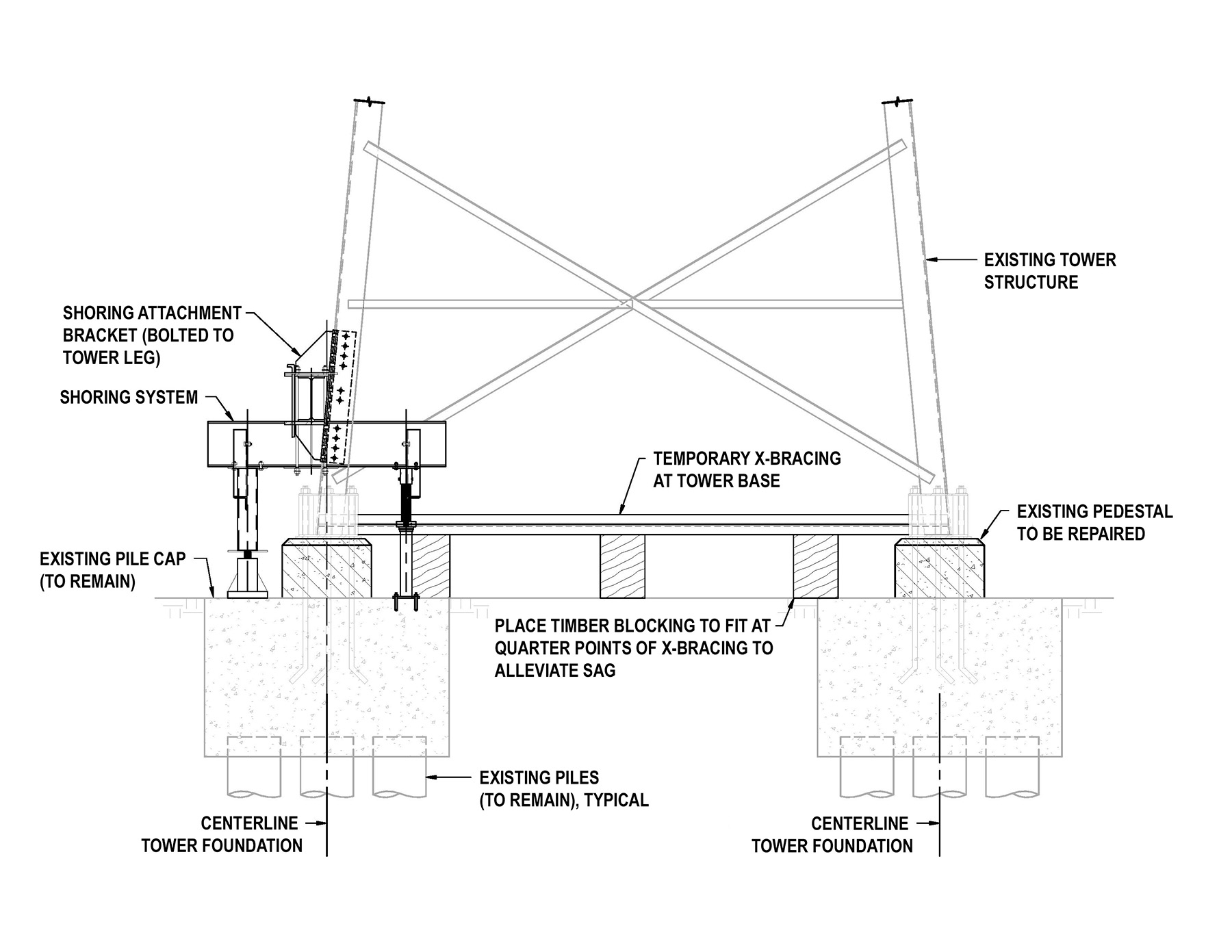
Additional considerations include site access constraints and whether the substation can be taken out of service during repairs, which is determined in consultation with the utility owner. A vital question is whether the superstructure can be temporarily removed to facilitate foundation remediation. If not, engineers must design shoring systems.
Shoring design
Shoring systems are subject to unique factors, including:
- Complex load conditions. Loads include dead and live loads as well as potential loads applied by wind, ice, and seismic activity, depending on the type of structure, location, or equipment being supported. The loads will come from the superstructure itself as well as the conductors and any electrical equipment the superstructure supports.
- Space constraints. Substation yards frequently offer limited vertical and horizontal clearance for large shoring frames or excavations. The constructability of the shoring system must be considered during all phases of its design, and early contractor input can be invaluable.
- Stability. Shoring systems should be designed to resist the actual loads that are anticipated to occur throughout the duration of repair. Designs that would support the maximum loads called for in ASCE’s Substation Structure Design Guide, Manual of Practice 113 and the National Electrical Safety Code (NESC) would likely result in an overly robust system that may not be cost-effective or constructable.
When original design drawings are incomplete or unavailable, engineers must rely on field measurements, owner-supplied data, and, in some cases, 3D terrestrial laser scanning to model the superstructure to analyze reaction (forces, moments) development. These reactions are used to design a shoring system that fully supports the superstructure, relieving the foundation of the loads so that remediation can occur.
A shoring system will likely require hydraulic jacks equipped with pressure gauges. This will allow the superstructure’s reactions to be precisely preloaded and transferred incrementally from the foundation to the shoring system. The hydraulic jacks should be continuously monitored to detect leaks or pressure drops that could compromise the integrity of the shoring system.
Because of their complexity, shoring and preloading operations must be clearly defined for the contractor. A properly developed shoring sequence, with step-by-step directions that convey the design intent and include site monitoring provisions, will facilitate the process for all involved.
Rivermines substation
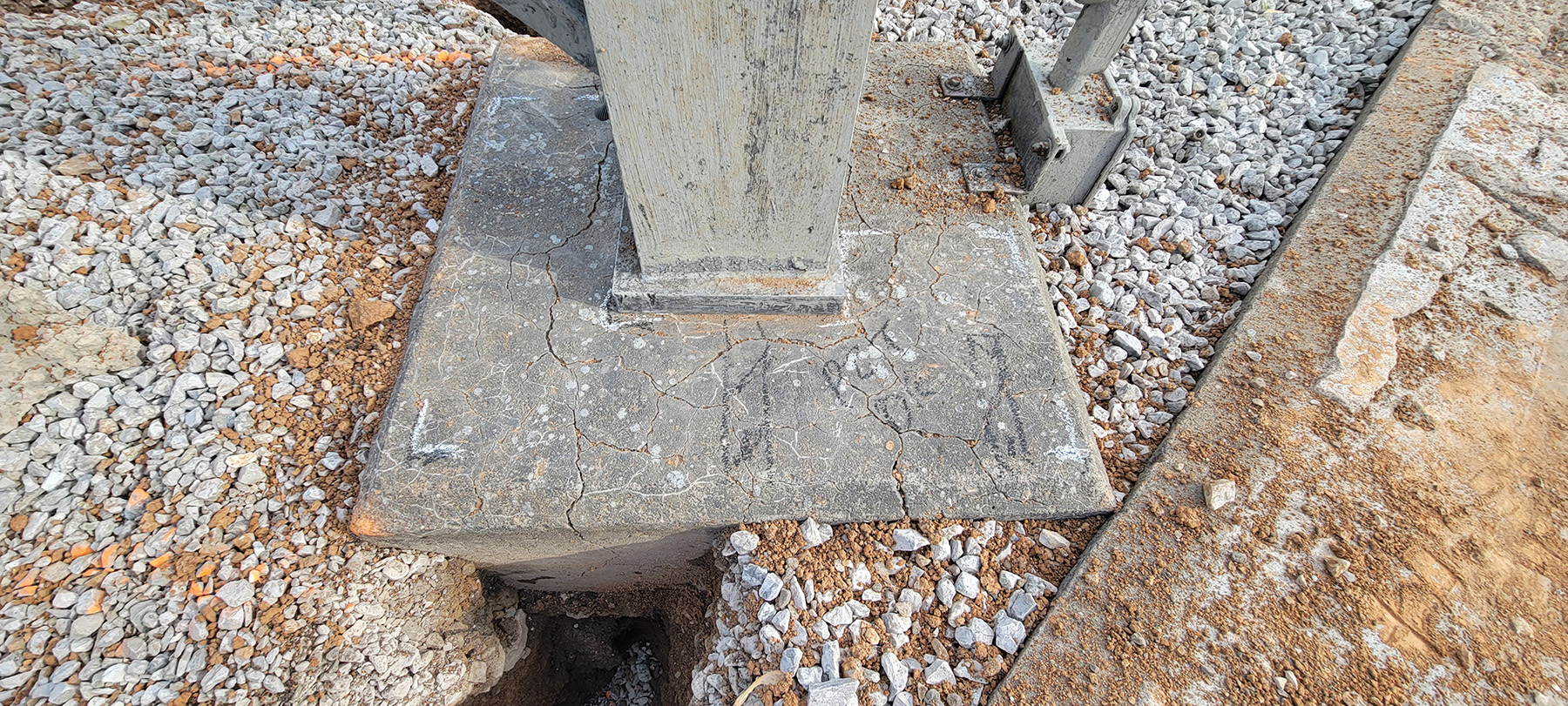
Ameren, an electric utility in Illinois and Missouri, owns and operates the Rivermines Substation in Missouri. Ameren engineers visually identified deterioration in six concrete piers supporting box bay structures. In early 2023, the company engaged Hanson Professional Services Inc., of Springfield, Illinois, to perform visual assessment, sounding, ground-penetration radar scanning, and core sampling for compression testing and petrographic examination of the piers.
Hanson engineers determined that the deterioration was limited to the upper portion of the foundations and was likely the result of freeze-thaw cycles, exacerbated by low entrained air content in the upper portion of the foundation concrete. The underlying concrete remained robust, with compressive strengths between 5,200 psi and 8,300 psi. After reviewing the test results and potential options, Ameren and Hanson decided to proceed with a partial foundation repair.
The remediation plan required a steel-framed shoring system designed to temporarily support the box bay structure. The shoring system relied on the high load-bearing capacity of the underlying foundation concrete. The deteriorated concrete was partially removed between the box bay’s steel legs to accommodate the shoring system. After the superstructure was shored, the contractor removed the remaining concrete, cleaned the existing reinforcement, installed new reinforcement dowels, and cast a new concrete cap. This two-phase operation was completed without requiring a substation outage, showcasing the feasibility of in-place partial repair. These repairs began in April 2024 and were substantially complete in May 2024.
Hanson also identified corroded anchor rods in the deteriorated portion of the foundation. To restore the tension capacity lost because of this corrosion, Ameren and Hanson agreed to implement a supplemental tower anchorage system, similar to a foundation bypass. Hanson’s plan used portions of a previous shoring system supported by independent micropiles on either side of the foundation for this bypass. The supplemental anchorage system was installed in May and June of this year.
Berkeley substation
Berkeley substation, also in Missouri, presented a different scenario. Because of the large quantity of foundations at the substation, Ameren’s consultant collected samples from a limited number of foundations that were considered to be indicative of the rest. Visual cues, confirmed with petrographic examination conducted in 2022, showed an alkali-silica reaction in 28 pedestals that were bearing on pile cap foundations. These foundations supported a dead-end box bay structure.
The pile caps were not deteriorated and remained in good shape, with compressive strengths between 6,600 psi and 9,600 psi; however, significant microcracking, spalls, and efflorescence were present in the pedestals. Because the deterioration was localized, Ameren and Hanson agreed to design a partial repair consisting of replacing only the deteriorated pedestals.
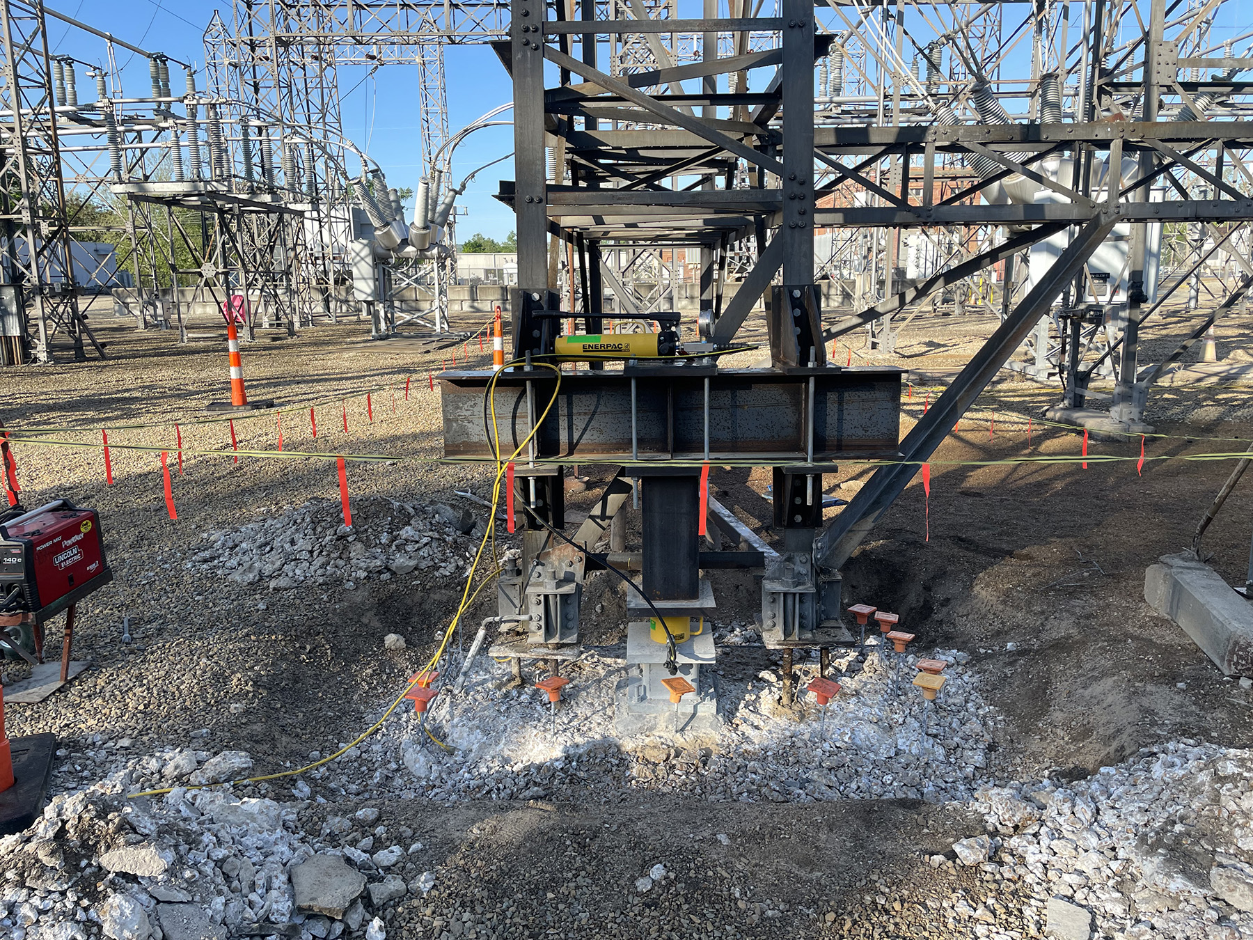
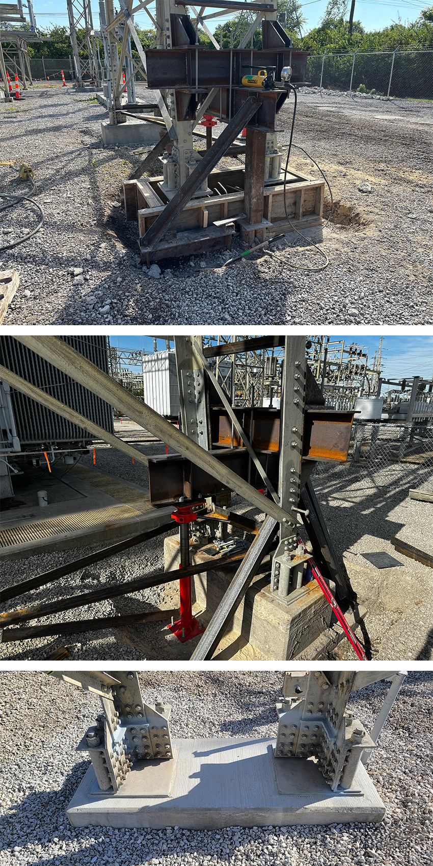
The remediation strategy for this site used the intact pile caps to support the loads of the steel superstructure. The shoring system consisted of steel brackets on the tower legs, a steel distribution beam between the brackets, and another steel shoring beam oriented 90 degrees to the distribution beam. The shoring beam was supported by a jack post on one side and a steel post on the other so that it could accommodate a hydraulic jack. The hydraulic jack lifted the shoring beam and distribution beam system to engage the vertical load of the superstructure.
The design called for steel braces across the steel superstructure legs extending down to the pile cap to resist the lateral loads from the tower legs. Once the shoring system was installed and engaged, the contractor removed the pedestals and recast them up to the bottom of the existing steel structure base plates.
This project required carefully sequencing the shoring installation and demolition of the 28 pedestals. The Hanson and Ameren team worked closely with the contractor from the start of the project to develop a sequence that met the design intent and addressed site constraints imposed by other projects occurring simultaneously. As the process was implemented, the sequence had to be revised so that crews could maintain access to the shoring and remediation activities.
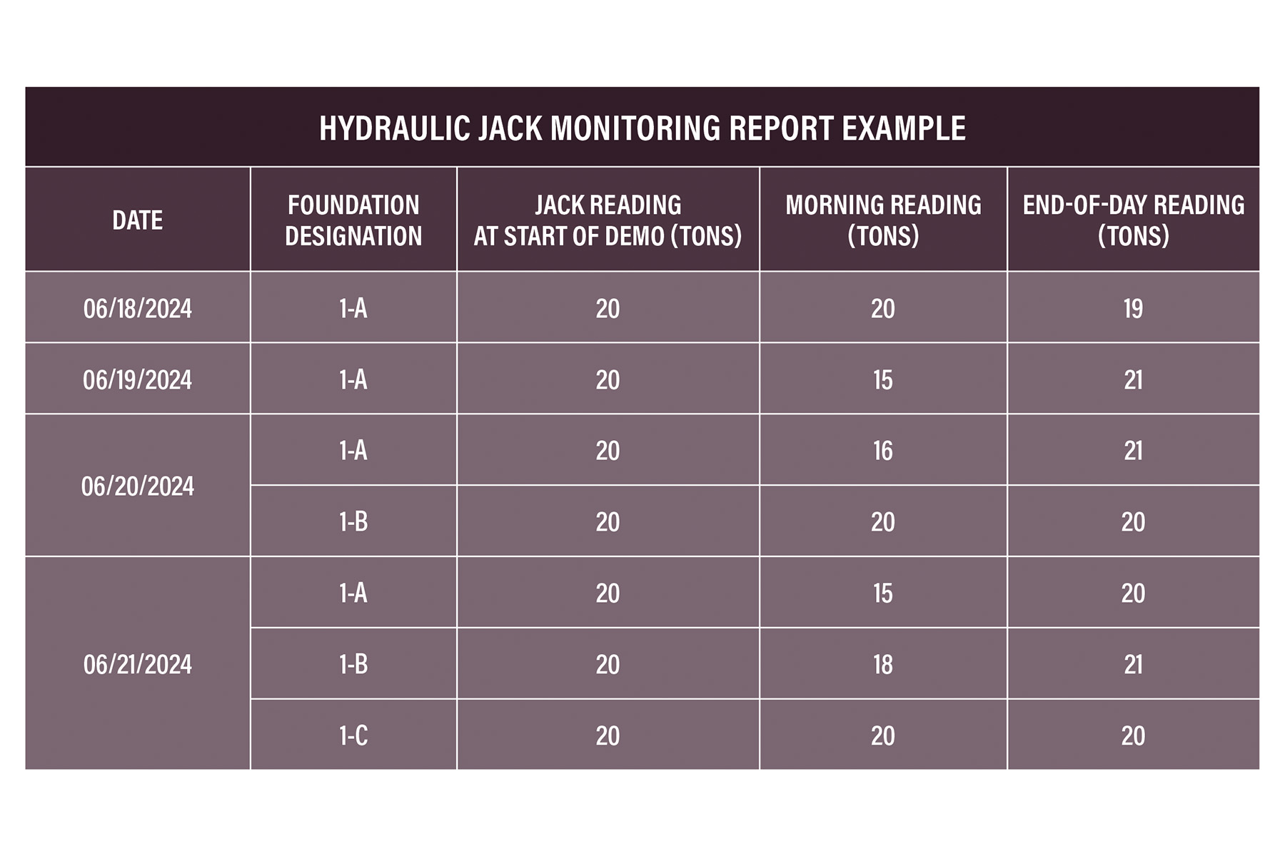
Adjacent tower leg foundations were not remediated simultaneously to maintain redundancy within the box bay system. The contractor monitored the pressures on the hydraulic jack throughout the repair process to confirm the loads were adequately supported (below).
All 28 pedestals were successfully remediated within approximately four months at the end of 2024 with no interruptions to substation service. When executing a project of this type, particularly when multiple contractors are on-site, constant communication and coordination between all parties is a necessity. Weekly virtual team meetings and daily on-site team meetings contributed to a safe and successful project.
Lessons learned
The Rivermines and Berkeley projects benefited from a number of elements.
The first was thorough preplanning. During the design, preconstruction, and construction phases of the projects, collaboration between engineers, contractors, and utility owners was vital to identifying constraints, clarifying procedures, and producing the best possible design and work sequence.
The authors developed a detailed sequence of construction for the work that matched the design intent and considered the existing structures’ load paths. Collaboration between the contractors and owners enabled adjustments to this sequence.
Careful observation was a second defining element to the project’s success. We preempted instability by diligently monitoring the hydraulic jack pressures and structural movements.
The contractor identified a leak in a hydraulic jack at the Berkeley substation prior to a pedestal demolition thanks to this monitoring. This allowed workers to install a replacement jack without compromising the stability of the shored structure.
Third was adaptable shoring. Modular designs accommodated irregular geometries and expedited assembly. These designs were crucial to minimizing the duration of construction.
When multiple foundations require remediation, a modular system reduces the cost of custom-fabricated components and allows the shoring to be reused.
This also ensures the shoring system remains similar between locations, making installation easier for the contractor’s crews.
Finally, staged construction played a pivotal role, enabling the teams to avoid compromising the integrity of the existing structures. Partial removal of a shoring system reduced the impacts of the remediation and became part of the final condition.
Also, the team reviewed the staging between remediation of multiple foundations of a larger interconnected system.
Concrete foundation deterioration is a challenge in aging substations, but it need not compromise grid reliability. By integrating rigorous assessment, innovative design, and meticulous construction practices, utility owners, structural engineers, and contractors can work together to extend the service life of critical infrastructure without disrupting operations.
Garrick Pitts, P.E., M.ASCE, is a civil/structural engineer with Ameren in St. Louis. Austin Dierkes, P.E., is a structural engineer with Hanson Professional Services Inc., in Springfield, Illinois. Ryne Fiorito, P.E., S.E., M.ASCE, is a structural engineer with Hanson in Springfield. Calvin Austiff, P.E., S.E., M.ASCE, is a structural engineer with Hanson in St. Louis.
This article first appeared in the September/October 2025 issue of Civil Engineering as “Repairing Active Substations.”
This article is based on a paper the authors presented at the ASCE Electrical Transmission & Substation Structures Conference September 14-18 in Dallas. The conference provides the perfect opportunities for utilities, engineers, suppliers, contractors, consultants, and industry professionals to learn, network, and do business.