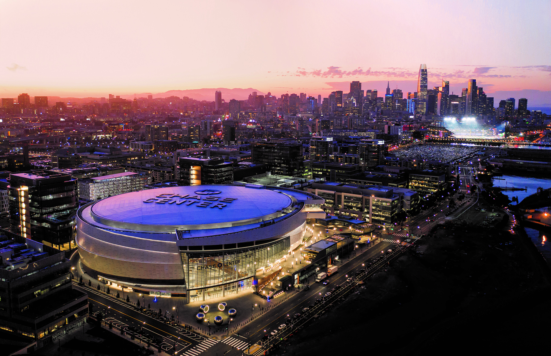
The Chase Center arena, which opened in 2019, is the capstone in the transformation of San Francisco’s Mission Bay neighborhood. The project has energized and engaged the neighborhood, completing the area’s conversion from a deteriorating industrial zone into a flourishing, urban entertainment center and transportation hub. The complex design modernizes the concept of an arena, catering to visitors of all kinds with year-round sports and entertainment events.
The project’s success is the result of a structural design that integrates an 18,000-seat National Basketball Association arena — home to the Golden State Warriors — with two 11-story office towers, an architecturally expressive jewel-box structure called the Gatehouse, 29 retail outlets, two atrium entrances, and a striking cantilevering “sky bar.” The structure features 360-degree access and 365-day operation.
All this was achieved despite extreme site conditions and program complexities.
With its location on reclaimed ground in a former shallow inlet off San Francisco Bay, the Chase Center’s geotechnical and environmental work was expansive, enabling the massive center to be built despite the site’s weak soils and high water table.
THE STRUCTURE
Triumph of teamwork
By Wyatt Henderson, P.E., S.E., and Emily Carlip, P.E., S.E.
Throughout the 2010s, the Golden State Warriors, led by superstars and remarkable team play, established themselves as the preeminent team in the National Basketball Association, winning three championships and enjoying one of the most dominant five-year runs in NBA history. At the same time that the players, coaches, and members of the front office were elevating themselves to the peak of the game, the Warriors’ ownership group saw another opportunity to add to the legacy of the franchise. Their vision was to create an iconic, first-in-class sports and entertainment venue as the team’s home, bring their operations under one roof, and create a lasting legacy in San Francisco. Chase Center brings this vision to life.
The Chase Center development is spread over a 780 by 650 ft site with multiple independent structures supported atop a common podium. Unlike most arenas, Chase Center has no back door. The structural engineering, performed by Magnusson Klemencic Associates (MKA), ensures that visitors can approach and enter the complex from all directions and experience unique views and vantage points as they do.
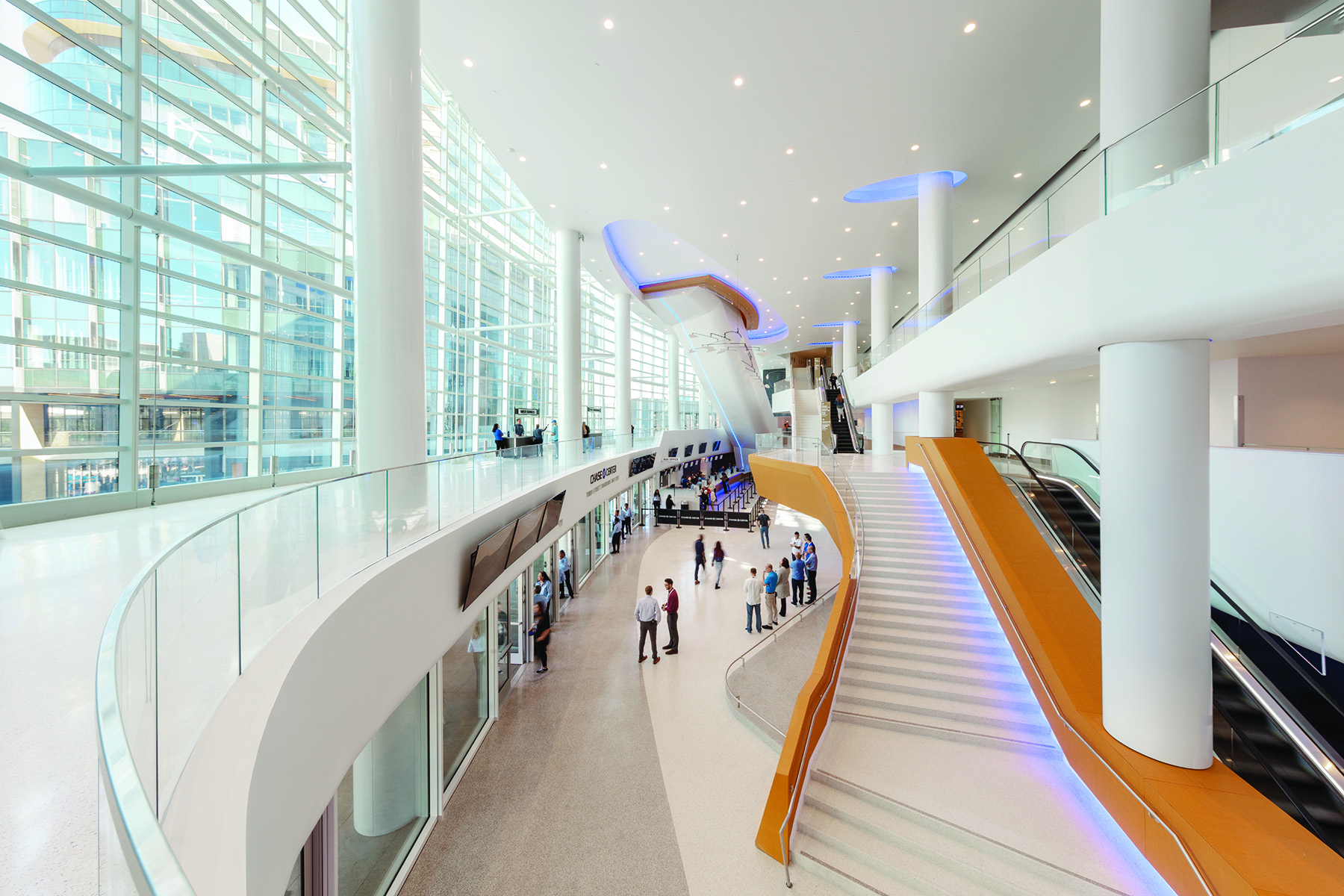
The arena occupies the east half of the site and features two major entrance points: a plaza, which is anchored by a large public art installation by Olafur Eliasson and leads to an 85 ft tall atrium lobby on the southeast side, and a series of landscaped ramps and stairs that leads to a massive raised plaza and second atrium lobby entrance on the west side.
The west plaza is overlooked by the Gatehouse — a twisting, jewel-box structure that provides terraced seating facing the arena’s exterior video board and a wall of curved glass facing the street. The Gatehouse not only acts as a site entrance but also serves as a unique wind blocker, an element deemed necessary by a pedestrian-comfort wind study. Two office towers command the site’s northwest and southwest corners.
Integrating all the project components while maintaining an active site from all directions required that key nonpublic program elements be hidden below grade. This included the Warriors’ practice facility, featuring two full-size NBA courts; a loading dock with room to accommodate five semitrucks; and two levels of parking with 950 spaces. A unique structural layout marries the arena’s radial column grid with the office/parking area’s orthogonal grid, minimizing column transfers and efficiently transferring the above-grade structural forces to the foundations.
Semitrucks access the below-grade ramp from a southern, single-lane entrance. This leads to a 250 ft long by 60 ft wide column-free space beneath the plaza that accommodates multiple trucks and has adequate space for each to fully turn around and exit back up the ramp. Built-up, 80 in. deep, steel plate girders, weighing up to 750 lb/ft, align with the office tower column grids above and span 60 ft, effectively transferring column loads and supporting the plaza loads above.
The Warriors’ below-grade double court practice facility is built in a 120 by 120 ft, column-free space. To avoid interfering with a critical parking drive aisle and the footprint for a potential future hotel development, it was necessary to push the practice facility under the arena footprint.
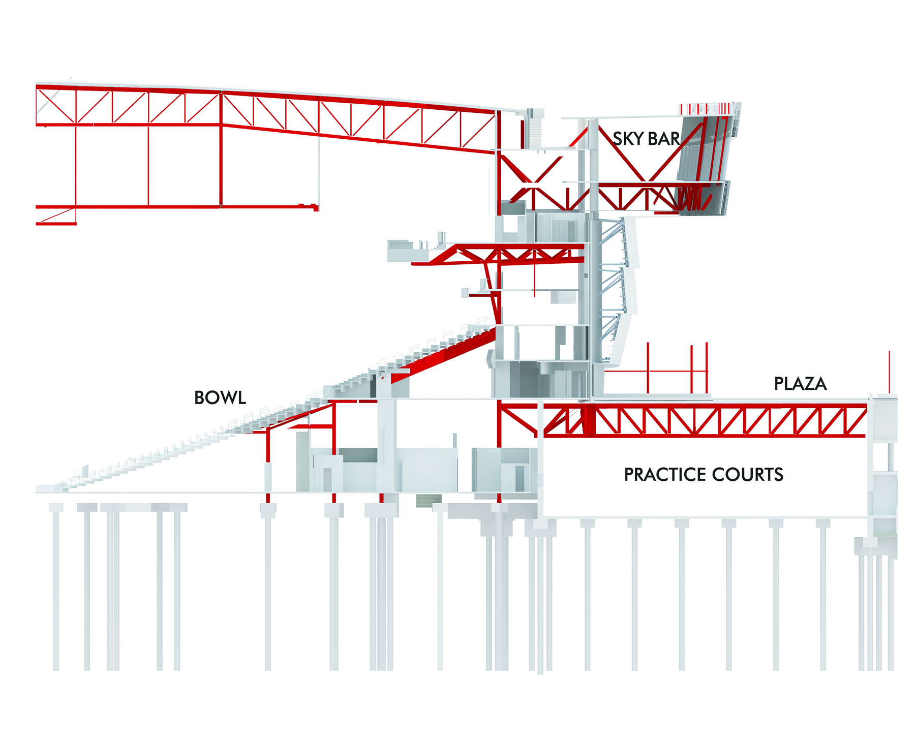
Radial trusses and a line of circumferential trusses follow the perimeter of the arena, transferring the four arena columns that support the “sky bar” above. This architecturally expressive bar and restaurant cantilevers 60 ft beyond the perimeter column line. The radial-truss-to-column-grid alignment integrated as part of the roof and facade system makes this achievement look effortless. The position and design provide incredible views of the Bay Bridge, an important nod to the home team since the bridge is featured in its logo.
The lid of the practice court serves as a pedestrian plaza and lookout over the bay. With multiple structural components interacting and with each subject to crowd-induced movements, vibration was a major consideration for the structural design. Detailed analysis models considered numerous combinations of activities — dining and dancing at the sky bar, cheering fans inside the arena bowl, and strolling pedestrians on the plaza — to ensure that occupant comfort in one area would not be adversely impacted by occupant actions in another.
Geotechnical nightmare
Adding to the challenges of integrating multiple program elements together and pushing significant column-free spaces below grade, a trifecta of site issues confronted the team: weak soils, extreme seismic demands from the nearby San Andreas and Hayward faults, and a high groundwater table — a design team’s geotechnical nightmare. These conditions made it clear that only a robust, below-grade structure with deep foundations could support the massive development. (See “The Geotechnics: Soil and Water.”)
The site consisted of layers of fill from the Great 1906 San Francisco Earthquake, weak/corrosive bay mud, and underlying Franciscan Complex bedrock, each with significant variation in depth and thickness across the site. Geotechnical engineering and environmental services company Langan Engineering and Environmental Services Inc. performed an exhaustive exploration of the site to map the soil conditions, and then developed maps breaking the site into eight zones with varying soil capacities.
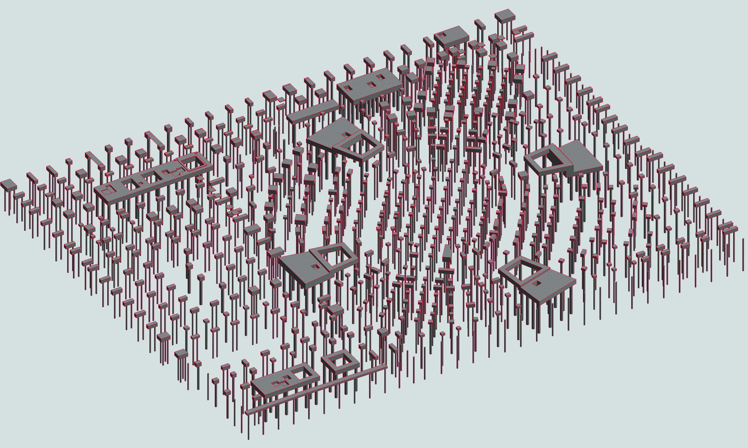
Building on that effort, Mortenson|Clark Joint Venture and Malcolm Drilling proposed a mix of deep foundation elements, including 24 in. diameter auger cast piles, drilled 10 ft into bedrock, and 36 or 48 in. diameter drilled shafts with the ability to extend further into bedrock to achieve higher capacities. Based on the specific column and wall loading at each location, the most efficient deep foundation members were selected to optimize the overall foundation system design, saving costs and preserving the schedule of the project.
Large-diameter drilled shafts were used to support the most heavily loaded elements, and the smaller auger cast piles were used at more lightly loaded locations.
An extensive in situ pile testing program verified the pile capacities, the results of which served as the final design criteria implemented by MKA. This optimized design approach resulted in just more than 1,300 deep-foundation elements comprising the three basic pile types with nine unique pile-reinforcing packages using bundled, grade 80 ksi spiral-confinement reinforcing to reduce congestion. Special detailing requirements associated with the site’s extreme seismic demands were implemented to ensure a ductile connection to the pile caps and adequate lateral strength and flexibility under seismic loading.
The variable ground conditions and weak soils complicated and amplified seismic shaking in the models, resulting in extraordinary demands on the overall structure — two to three times that of typical structures. The seismic interaction between buildings required the development of first-of-their-kind analysis tools. A linear time-history analysis was used to capture multibuilding behavior more accurately. Seismic ground-motion simulations, developed and applied in 30-degree increments, captured a full 360-degree response. Custom-built tools to post-process the results created demand curves capturing the distribution/transfer of seismic forces at the podium, which allowed for more robust and reliable earthquake-response predictions and a more efficient design.
The site is located immediately adjacent to San Francisco Bay, resulting in a groundwater table that is a mere 10 ft below grade. Significant hydrostatic-uplift pressures, in some locations in excess of 800 psf, affected the design of the perimeter basement walls and the robust structural slab-on-grade and deep foundations. Beneath the practice facility and the event floor, deep foundation elements act as hold-downs to ensure that the slabs do not float upward.
Functional flexibility
Adaptable, functional, and efficient, the structural design of the arena caters to a range of different event configurations — a true multifunctional entertainment venue as opposed to just a basketball facility.
Four primary trusses span up to 358 ft across the event floor along with a series of radial end trusses and in-fill transverse bridging trusses. The primary and bridging trusses are spaced to provide a 90 by 60 ft void in the roof truss volume. The 42 ft truss depth provided adequate room for the scoreboard — the NBA’s largest — to nestle within yet clear the bottom chord of the trusses, resulting in unobstructed views for concert attendees.
A high-capacity rigging grid and catwalk, complete with a tension-grid walking surface, are integrated into the bottom chord elevation. Two center roof trusses support an underslung rail system for a one-of-a-kind, operable, gantry-rigging grid system. The gantry rolls into place to cover the void when the scoreboard is retracted into the roof depth. This improves visibility and provides flexibility for concerts and small theater events.
To successfully erect the long-span roof, the sequence of construction was critical. Close team collaboration ensured consistency with analysis and design assumptions. Each primary truss was stick-built in two sections on the ground, lifted into place, and supported from shoring towers at midspan while being spliced together. Two primary trusses, one set of end trusses, and the associated bridging trusses were erected fully connected, then deshored.
The process was then repeated on the other half, reusing the two shoring towers, and completed with in-fill framing between the halves.
Team triumph
After years of local jurisdictional planning and reviews, the project was fast-tracked at the end of schematic design in April 2016, with procurement of major structural trade packages beginning two months later. Key trade partners (for the deep foundations, structural steel, precast concrete, cast-in-place concrete and reinforcing, facade, and mechanical, electrical, and plumbing) were employed early in design-assist roles.
The bid/procurement process was carefully and collaboratively navigated by the owner’s representatives, the design team, the general contractor, and the lead structural engineer to manage the risks and costs associated with early procurement. (See the project credits list.) This ensured the complete structural scope was captured with the added benefit of early subcontractor input on critical systems.
MKA also worked closely with the governing jurisdiction and seismic peer reviewer on a phased-permit approach that was necessary to meet the schedule. Staggered permits allowed foundation construction to begin on time, while design of the superstructure was still being completed.
In all, three structural bid packages and seven structural permit packages were delivered on an aggressive schedule, resulting in uninterrupted construction. Final structural steel quantities were within 3 percent of the initially estimated quantities — a remarkable outcome, given the complexity and speed of the project.
Construction began in January 2017 and topped out in September 2018. The venue opened in September 2019 with a concert event featuring hometown heroes Metallica and the San Francisco Symphony.
THE GEOTECHNICS
Soil and water
By Lori A. Simpson, P.E., G.E., M.ASCE, and Dorinda C. Shipman, P.G., C.HG
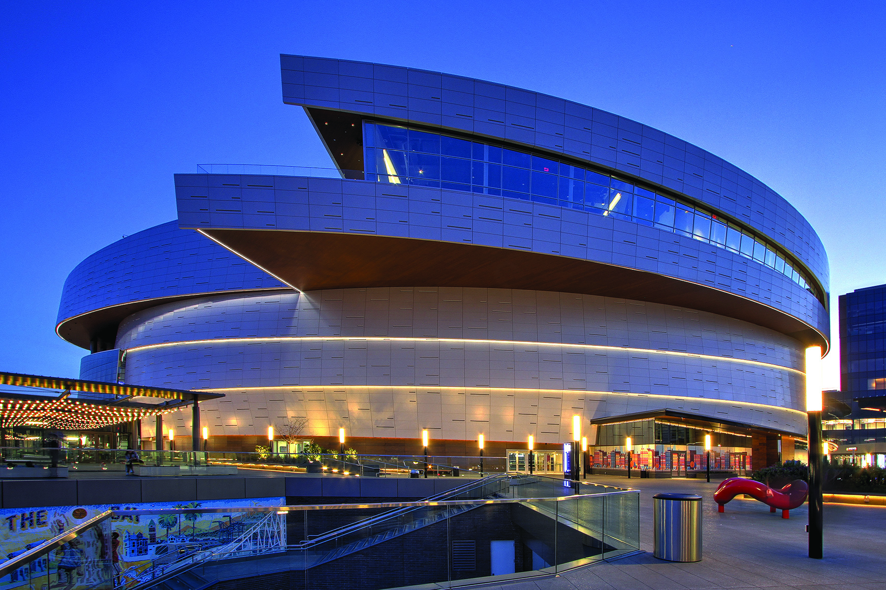
Look around San Francisco’s Mission Bay neighborhood, and you’ll notice a new state-of-the-art arena that appears to be rising from San Francisco Bay: Chase Center, home of basketball’s Golden State Warriors and a must-play tour stop for some of the biggest acts in the music industry. Designed by Manica Architecture, this beautiful arena stands out in a busy neighborhood known for state-of-the-art research, laboratory, and commercial facilities and a new campus for the University of California, San Francisco.
Mission Bay, originally a shallow inlet off San Francisco Bay, was fed by Mission Creek, which flowed down from Twin Peaks, one of San Francisco’s famous seven hills. Marsh and rocky cliffs surrounded the bay at this time. During the California Gold Rush, the city’s population and footprint grew, and more and more of the shallow bay was filled to create land and to access what is now the southern part of San Francisco.
Over the decades, Mission Bay was reclaimed using a variety of materials dumped into the bay — sand from nearby dunes leveled for development, various soils excavated for construction in other parts of the city, bedrock rubble cut from nearby hills, building debris after the Great 1906 San Francisco Earthquake and the subsequent fire, and even garbage from when part of Mission Bay was used as a dump.
Over time, Mission Bay became known as an industrial part of the city — occupied by a rail yard, warehouses, oil terminals, a concrete plant, and vacant land. In the 1990s, a 300-acre parcel fronting San Francisco Bay was approved for redevelopment. Originally, this plan did not include a venue for a basketball team, but over time, the plan for an arena came together when a four-block parcel became available at the same time that the Warriors were looking for a site.
Langan Engineering and Environmental Services Inc. has long provided geotechnical and environmental services in Mission Bay; the company was involved in the original 1990s redevelopment planning phase and continued to provide services during design and construction of most of the new buildings and infrastructure there. Langan began lending its geotechnical and environmental expertise to the design and construction of Chase Center during early planning in 2013.
What lies beneath
For the Chase Center project, Langan explored the site using borings, cone penetration tests, test pits, soil and rock sampling, and groundwater piezometers. The team found that fill from reclamation at the site had been placed over bay mud, a very soft to medium-stiff marine clay. The fill thickness — ranging from less than 10 ft to more than 30 ft — was indicative of a “mud wave” that occurs when too much fill is placed at once on the weak bay mud, causing a bearing-capacity failure in which the bay mud level drops under the fill and bulges up on the sides. This phenomenon was expected because of the history of dumping fill onto the bay mud, but the locations of mud waves were, and remain, difficult to predict.
Underlying the bay mud is the dense to very dense sand of the Colma Formation, stiff to hard clay known as Old Bay Clay, and intensely fractured and deeply weathered Franciscan Complex bedrock. Each soil layer varies significantly in thickness across the site, and the depth to bedrock varies from about 30 to 130 ft below the ground surface. Because of the site’s proximity to the bay, groundwater is shallow, typically 6 to 12 ft below the surface.
The fill includes cobble- and boulder-sized pieces of serpentinite, which contains naturally occurring asbestos, and other materials. A portion of the fill was characterized as a State of California Class I hazardous material based on soluble chromium, lead, and nickel concentrations, which are common in Mission Bay fill created from earthquake debris. The fill also contained residual petroleum hydrocarbons related to underground storage tanks that had once been on the site and to a former fueling pier located adjacent to the site. (Cleanup of the fueling pier required soil removal and groundwater monitoring on- and off-site.)
The known contamination within Mission Bay was handled during redevelopment in accordance with the California Environmental Protection Agency’s Risk Management Plan, which was published in 1999 and approved by the California Regional Water Quality Control Board, the California Department of Toxic Substances Control, and the San Francisco Department of Public Health for use on all Mission Bay projects. Langan completed a phase I environmental site assessment (site history) and a phase II environmental site characterization and devised a site mitigation plan to manage potential risks during construction.
A basement like no other
Because the plan for Chase Center included a below-grade event level, parking, and a state-of-the-art performance and training complex that included two full-size practice courts, an excavation as deep as 30 ft was necessary. This depth meant that most of the contaminated fill had to be excavated and hauled off site. The excavation reached lower than the groundwater level and, throughout much of the site, bottomed in the weak bay mud.
The system to support the excavation had to shore up the sides of the basement excavation, extend deep enough to develop adequate resistance to the earth pressure, and create a groundwater cutoff so that the excavation could be dewatered. The depth of the cut was unprecedented in Mission Bay; previous projects had shied away from anything more than a partial basement level because of the soil contamination, shallow groundwater, and weak soil.
Langan conducted three single-well tests and a 24-hour constant-rate pumping test to verify the aquifer parameters. The team also performed continuous groundwater monitoring to assess tidal effects on the hydraulic gradients and developed a numerical groundwater-flow model to assess the subgrade structure and cutoff wall designs and the dewatering scenarios for various construction schedules.
The modeling results were used to facilitate a design that would efficiently remove water from the fill and control inflow before foundation placement, limit settlement issues, and enable the team to meet the schedule milestones.
Because the bay mud is relatively impermeable, groundwater within the clay could not be lowered beneath its surface by active dewatering; therefore, passive systems of sumps and pumps were used to keep the excavation surface free of water. Additionally, an area with thin bay mud required an internal cutoff wall extending into Old Bay Clay and bedrock; here, shallow dewatering wells were installed in the fill and deeper dewatering wells were installed in the Colma Formation to control upward hydraulic pressure and minimize water inflow.
Based on heavy demands on San Francisco’s southeast wastewater treatment plant, Langan assessed — via groundwater volume estimates and a groundwater-treatment pilot study — the potential to discharge to the bay and obtained authorization to discharge treated dewatering fluids. The engineers also worked with the Port of San Francisco to use an out-of-use outfall to avoid having to construct a new discharge line beneath an adjacent roadway.
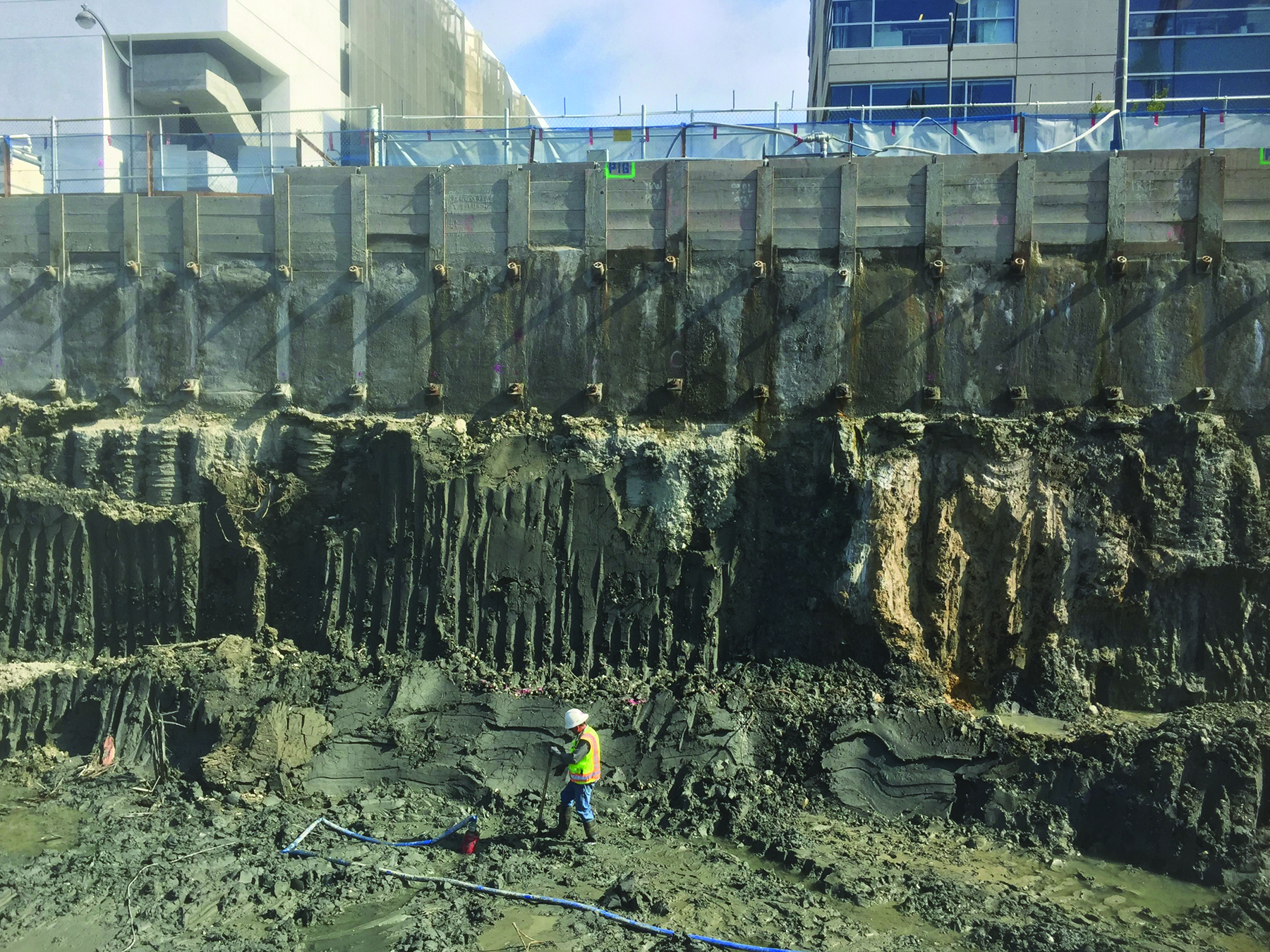
Condon-Johnson & Associates designed and installed a tied-back, continuous, cement deep-soil mixing shoring system to support the excavation walls and the surrounding improvements and to cut off groundwater. Langan provided the lateral earth pressures for the design and developed a number of earth-pressure diagrams because the subsurface conditions varied around the perimeter. The 3,200 ft long shoring wall was installed using a triple-axis soil-mix rig with soil-mix panels extending 25 to 75 ft below the ground surface.
Up to three rows of tiebacks were installed to laterally restrain the shoring. But to limit their length in weak bay mud, the tiebacks had to be installed either at very shallow angles (5 degrees) to remain within the fill or at very steep angles (45 degrees) to reach the dense Colma Formation sand or bedrock. In all, 1,200 tiebacks as long as 100 ft were installed.
Langan assisted the contractors in profiling the fill so it could be hauled away and disposed of or reused and in managing stockpiles before off-site transport. Using the environmental soil characterization and waste profiling data, Langan’s site and civil engineers created a 3D earthwork model to calculate grading quantities for waste categories, which included California Class I hazardous waste, Class II nonhazardous waste, and native soil suitable for unrestricted reuse.
The team also designed an excavation plan that encompassed the complicated and detailed environmental remediation and subgrade preparation for installing the foundations.
The local health code required the project to follow an approved dust control and monitoring plan. Additionally, state regulations required that projects disturbing more than an acre of land where naturally occurring asbestos is present to prepare an asbestos-dust-mitigation plan. Langan prepared and implemented the dust monitoring and mitigation plans and worked with the construction team to manage dust compliance.
A winning foundation
It was known in advance that the bay mud throughout the site was too weak to support construction equipment that would need to apply pressures of as much as 6,000 psf at the bottom of the excavation; therefore, a working platform was needed to provide a safe, stable surface. The working platform comprised Tensar TriAx TXI30S Geogrid interlayered with 3 to 6 ft of cement-treated fill or lime-treated bay mud. This working platform provided support for the numerous rigs, cranes, and trucks working in the excavation and helped maintain a relatively dry excavation bottom.
The extremely sloping bedrock and its low strength created a challenge for developing adequate capacity in the deep foundations. In particular, the four structural cores in the arena had very high load demands in compression and uplift, and the foundations had to be embedded far enough into rock to develop most of their capacity in friction and end bearing. Where depth to rock was shallow, there was little soil above it to contribute much capacity. Where rock was deep, the stronger soil was counted on for capacity, but the foundations still had to be embedded into bedrock to develop full capacity.
In locations with high load demands, the foundations consisted of 3 to 4 ft diameter drilled shafts with 12 to 65 ft long rock sockets. The rest of the columns were supported on 18 in. diameter, augered cast-in-place piles that extended 10 ft into bedrock. This combined foundation system was proposed by Malcolm Drilling, the foundation contractor, to provide an efficient foundation that reduced the risk of delays during installation.
Because of the extreme variation in thickness of the soil layers and the depth to bedrock, Langan worked closely during design with Magnusson Klemencic Associates to estimate foundation lengths at each of the 1,300 pile locations. Despite efforts to predict these lengths, the uncommon variability of Mission Bay meant that during pile installation, Langan logged the soil and bedrock conditions and determined pile lengths in real time. Because each pile had a reinforcing cage that had to be adjusted on the spot if pile lengths changed, the ability to make these adjustments was planned by Malcolm Drilling.
On-time completion
With the National Basketball Association calling the shots, there was zero flexibility on the completion date. The home opener was scheduled, and nothing could change it. To up the ante, the Warriors organization planned numerous concerts at Chase Center, with the first more than six weeks before the opening regular-season home game. The facility had to be ready to go only 32 months after groundbreaking.
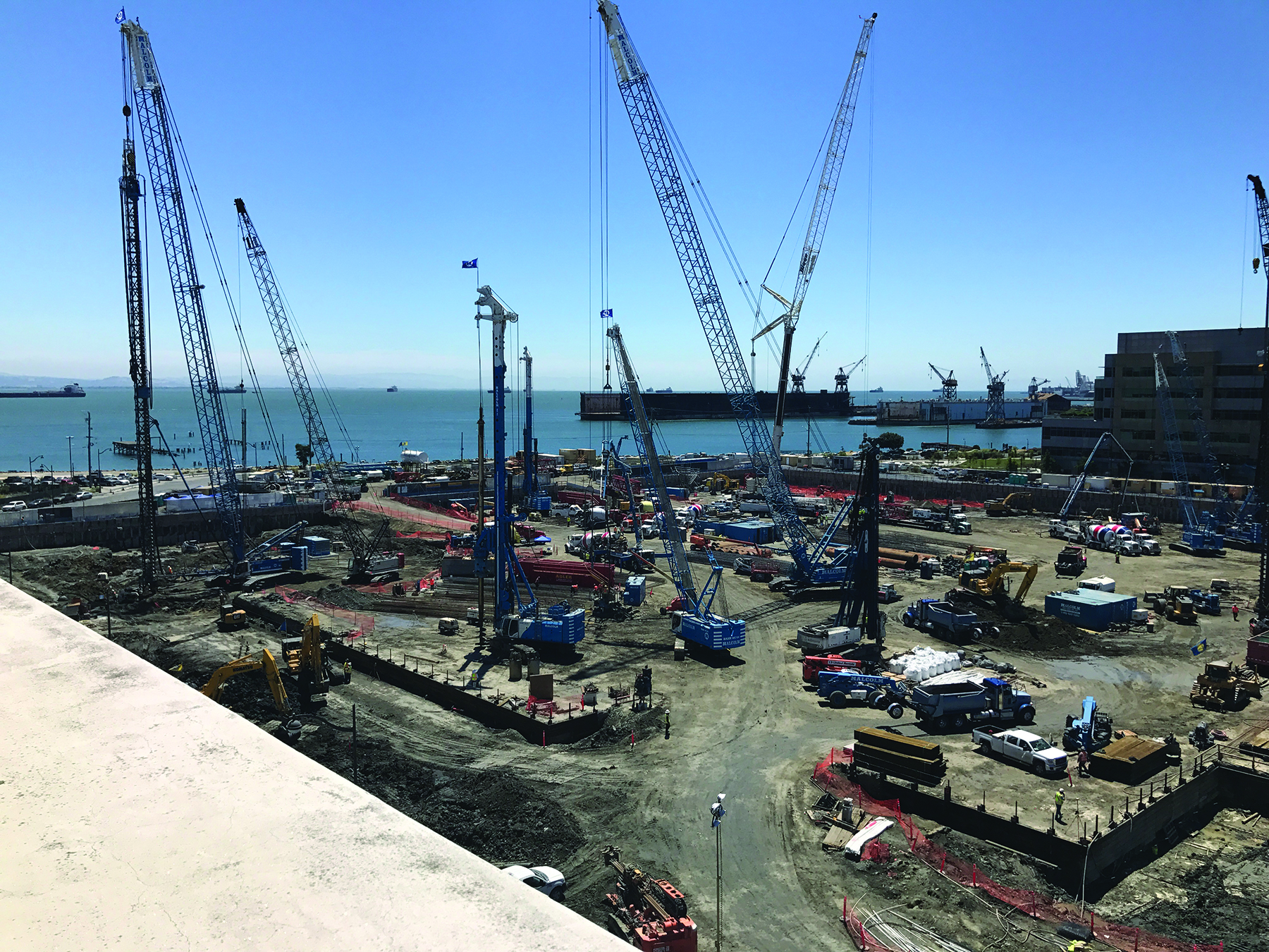
To meet the deadline, there had to be an enormous amount of planning, strategic forecasting, and coordination — led by the general contractor, a joint venture of Mortenson and Clark. As many as four foundation rigs and support cranes were installing foundations at once while three tieback rigs worked their way around the perimeter, and numerous excavators and dump and transport trucks kept the excavation proceeding to final subgrade.
Langan had two small-business partners: Albion Environmental and Divis Consulting. With the former, Langan had environmental compliance and monitoring staff on-site daily and with the latter, as many as seven inspectors on site observing the geotechnical aspects of shoring and foundation installation.
During the excavation, Langan’s soil excavation plan enabled contractors to mark areas of different waste and position trucks and waste haulers so that they could load directly whenever possible, saving time. During asbestos dust monitoring, measured levels increased where more serpentinite was present, prompting some temporary work shutdowns that required additional dust-control measures, but the work remained on schedule.
On September 6, 2019, Chase Center opened on time for its first official event — the Metallica and San Francisco Symphony concert. Being able to anticipate the adverse conditions that would be encountered on the site allowed the construction team to work from a playbook that identified such issues early on and provided solutions that could be implemented on time. (See “The Structure: Triumph of Teamwork.")
In the end, the extraordinary amount of planning and team collaboration that began in 2013 produced a state-of-the-art facility that, in addition to being the home of the Warriors, hosts numerous events, including concerts, cultural events, family shows, and more.
PROJECT CREDITS
Arena owner/operator: Golden State Warriors, San Francisco
Office owners: Golden State Warriors; Alexandria Real Estate, San Francisco; and Uber, San Francisco
Owner’s representative: CAA ICON, Denver
Architect of record: Kendall/Heaton Associates, Houston
Arena design architect: Manica Architecture, Kansas City, Missouri Structural engineer Magnusson Klemencic Associates, Seattle, with local small business enterprise partner OLMM Consulting Engineers, San Francisco
Geotechnical and environmental engineer: Langan Engineering and Environmental Services Inc., San Francisco, and Oakland, California, offices
Gatehouse design architect: SHoP Architects, New York City
Mechanical/electrical/plumbing/fire: Smith Seckman Reid, Nashville, Tennessee
Landscape architect: SWA Group, San Francisco office
Civil engineer BKF Engineers, San Francisco office
Foundation contractor: Malcolm Drilling, San Francisco
Excavation support: Condon-Johnson & Associates, Oakland, California
Environmental compliance: Albion Environmental, Santa Cruz, California, office
Shoring and foundation inspection: Divis Consulting, San Francisco
General contractor/construction manager: Mortenson|Clark Joint Venture, San Francisco
This article first appeared in the December 2020 issue of Civil Engineering as "Transformation All Around."
The cover photograph is courtesy of Jason O'Rear/Chase Center.