By Amy Harrington and Justin Den Herder
It was only fitting that the design of a center dedicated to the visual arts on the campus of Franklin & Marshall College feature an interplay of materials — from glass and concrete to steel and wood. But the structure’s unique design also called for another type of interaction, namely transformative cooperation between engineers, architects, fabricators, and builders.
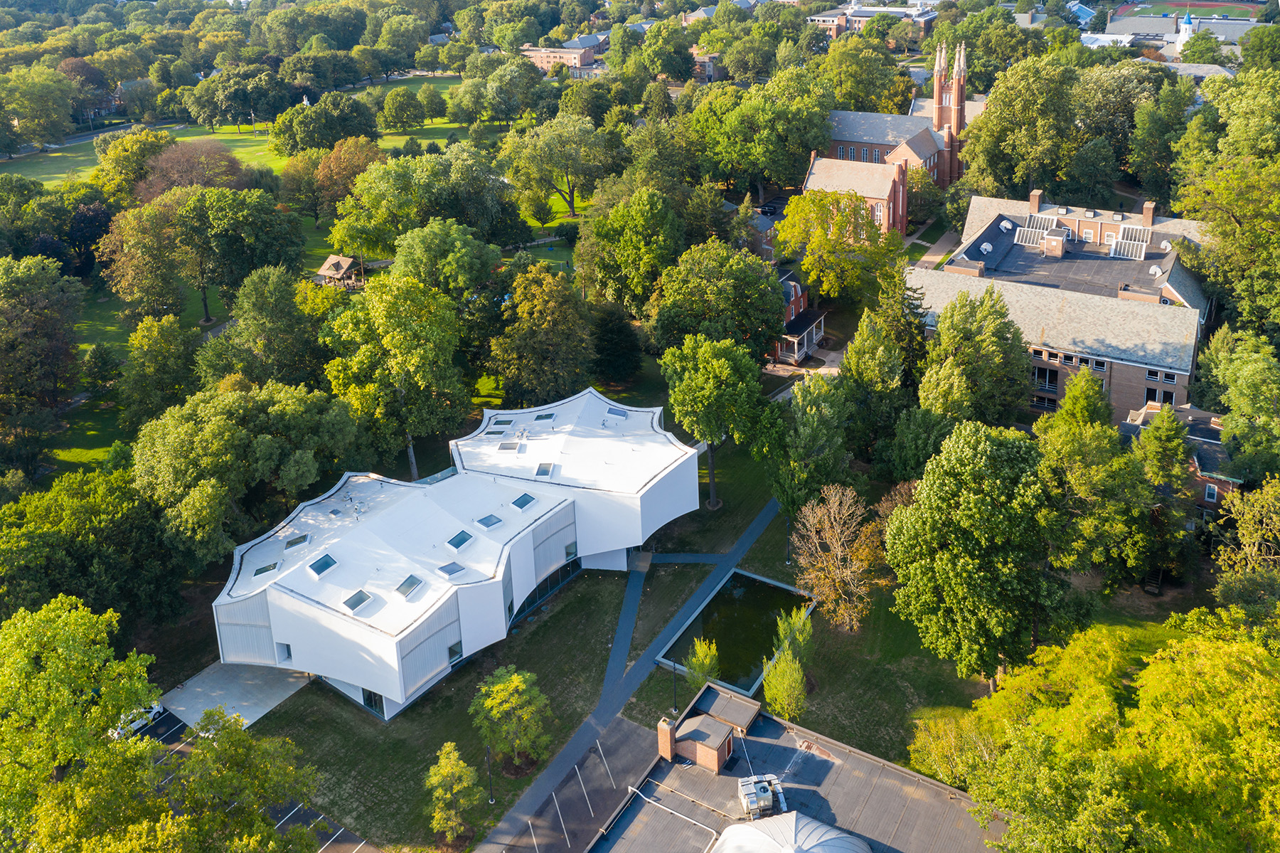
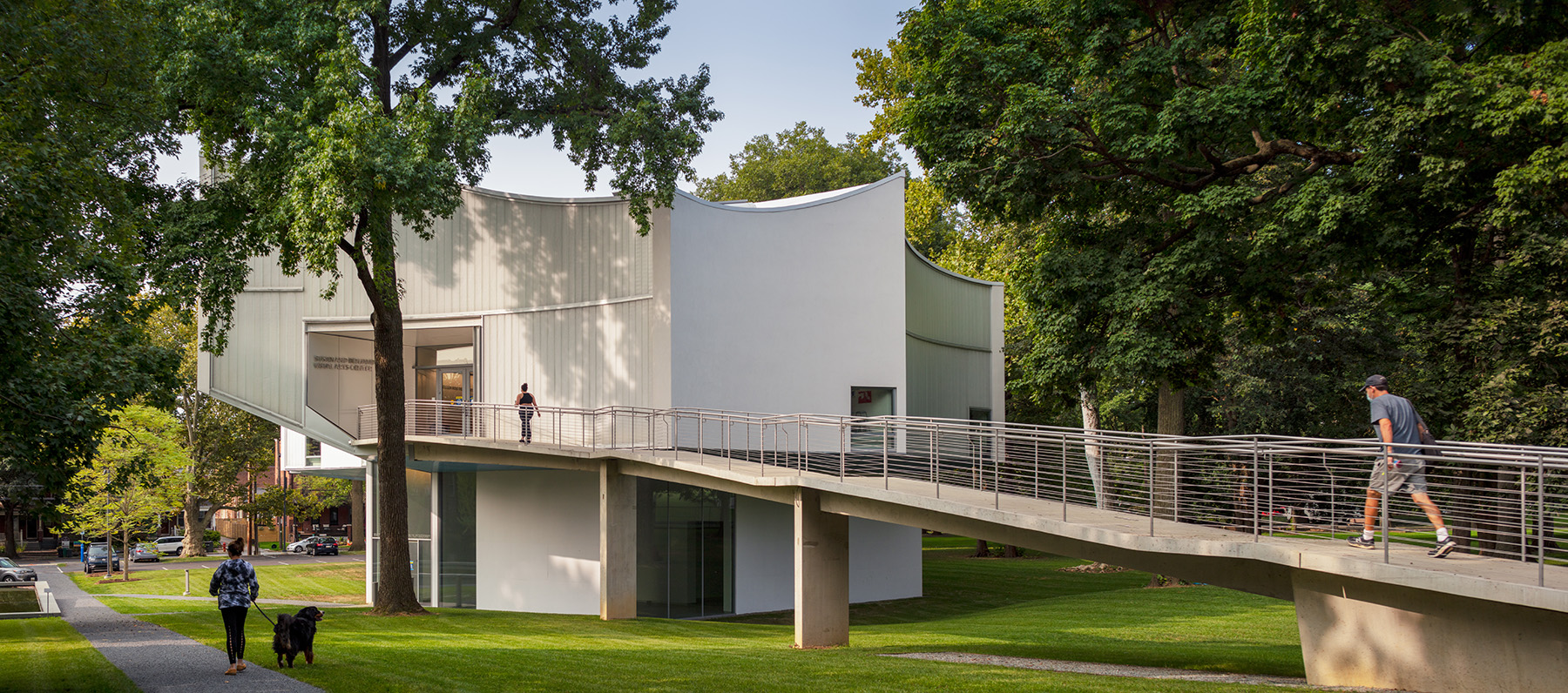
The Susan and Benjamin Winter Visual Arts Center is a new landmark on the historic Franklin & Marshall College campus in Lancaster, Pennsylvania. The 33,000 sq ft building replaces the 1970s Herman Arts Center and provides studios, classrooms, a cinema, galleries, and an exterior terrace for the college and the community.
The design of the building by Steven Holl Architects, also known as SHA, symbolizes a kite stuck in a tree (the “Franklin” in Franklin & Marshall referring to Benjamin Franklin), and its lightweight, floating appearance is an intentional departure from its predecessor. Silman served as the structural engineer for the project.
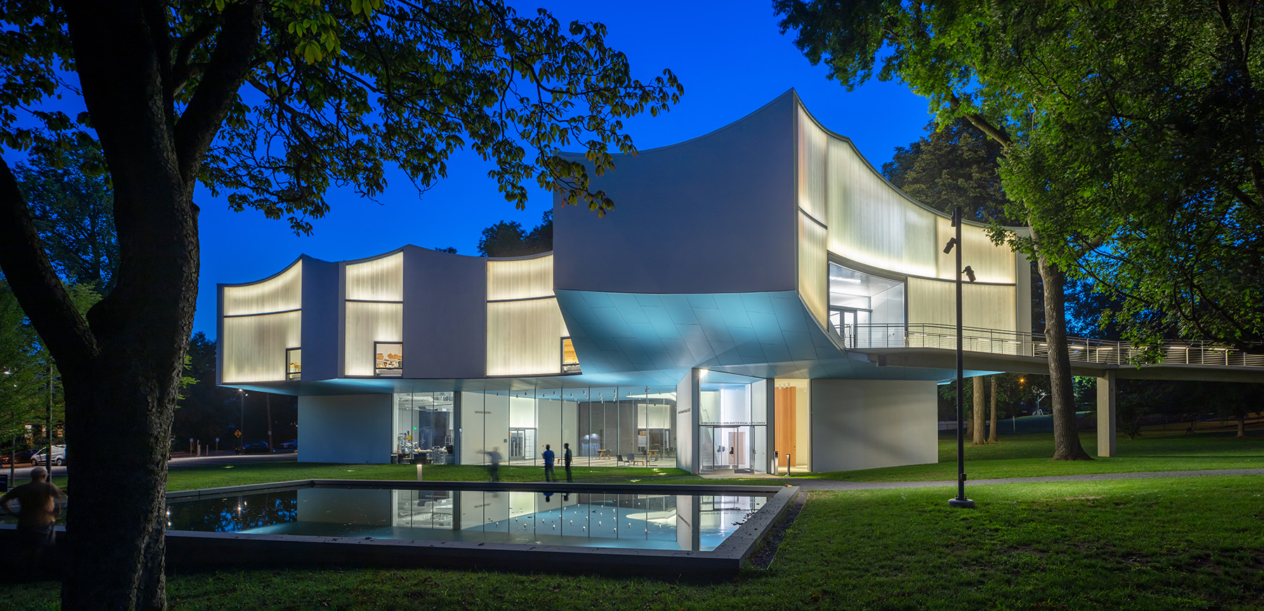
The concave geometry of the building’s second floor and roof plan are responses to the canopies of the surrounding old-growth trees and grant the building its spectacular form. The open ground floor serves as an extension of the campus grounds. The translucent facade, illuminated at night, creates an airy building in response to the other, more stoic brick buildings on campus.
The curved facade is supported by a continuous exposed moment frame comprising rolled steel tubes. The second floor cantilevers in many directions toward the surrounding tree canopies using two-story steel trusses positioned within the interior walls. The ground floor is maintained as a column-free space by using exposed concrete walls as the sole supports for the steel trusses above.
Since much of the structural system was intended to be arch-itecturally expressed, coordination and clarity of structural behavior were vital to the success of the project from the early phases of design through construction.
Initial layout
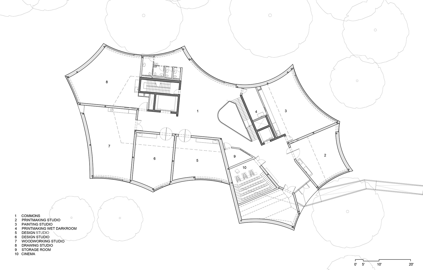
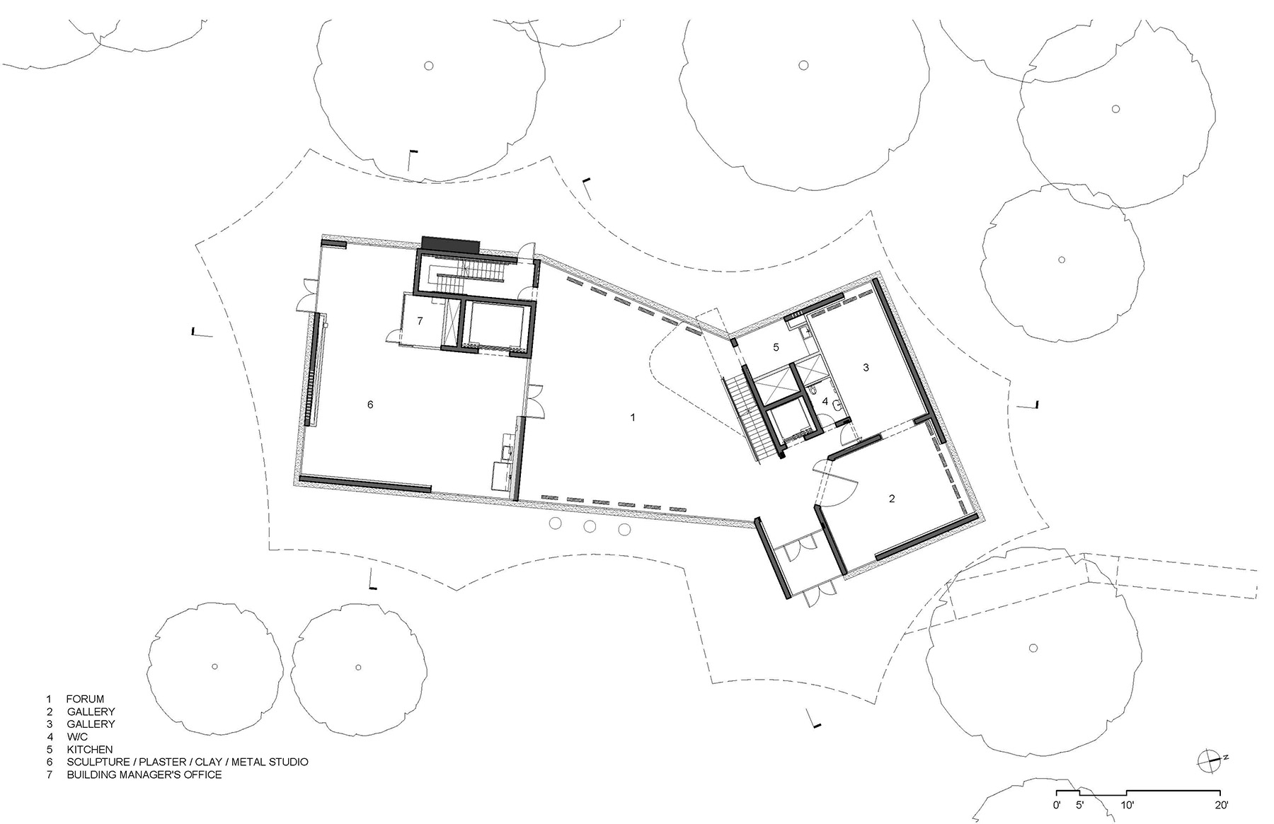
The two-story building, with a basement level and a mezzanine, is framed with composite steel framing spanning between the trusses and concrete walls. At the roof, tongue-and-groove wood planking is draped between curved hollow structural section round members.
The schematic design phase of the project was critical to laying out a structural road map that could be carried through to the later phases of the project. Silman’s engineers worked closely with SHA to align the trusses within the second-floor studio partition walls and enable horizontal spans between the two interior concrete cores and a small number of concrete walls at the perimeter of the ground-floor footprint.
To study the initial truss layout, we first mimicked the behavior of the complex trusswork by modeling long-span cantilevering girders. This “free body diagram” model gave us a good sense of the load path, the order-of-magnitude forces, and the stiffness required. It also allowed for quick iterations as the architectural layout evolved.
With more than half the floor area above the ground cantilevering beyond the first-floor envelope, understanding the building move-ment was critical throughout the design process. From the 2D model, the stiffness required at each truss was determined from the magnitude of moment seen in each truss element, which in turn, informed the proportions and configuration of the trusses and support points. Once we began modeling the trusses in their true complexity as we transitioned into design development, this simplified model was a helpful reference to validate our results and served as a useful reference for the global behavior of the building.
The connection of the truss frames to the spandrel moment frame was a key detail studied in the early phases of the design. In this location the truss served as a vertical and lateral support point for the spandrel frame. To maintain a slender steel section at the facade support, the connection of the spandrel tube to the truss node was designed as a fixed connection. To reduce the field welding required at this joint, we developed a strategy to construct the end truss node in the steel shop with stubs of the spandrel attached to the node. Working through this detail at the same time as the initial framing studies helped inform the design of the truss and spandrel frames and provide a strategy for constructing the intertwined geometry.
Steel framing
A 3D model of the building was created in the structural analysis program ETABS to analyze and design the concrete walls and steel framing of the building. Due to the building’s complexity, we investigated each system of the structure independently by building the model in stages to understand the structural behavior of each component before analyzing the building’s structure as a whole.
First, the concrete shear walls were modeled to confirm that the core layout provided enough stiffness to resist the lateral load of the building. From there, the trusses and spandrel frames were added to the model to analyze the truss frames. Finally, the steel infill framing at each level was added to get a complete analysis of the trusses and secondary framing.
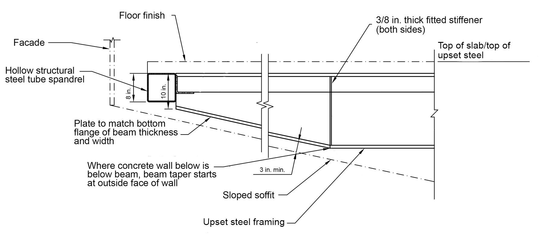
The truss design was informed by the architectural programmatic needs at the second floor and mezzanine. The layout of the diagonal members and open panels within the trusses were coordinated around circulation needs. All the truss members were limited to widths of 8 in. to fit within the partition walls. The top and bottom chords of the trusses were sloped and kinked to form the geometry of both the roof at the top of the truss and the sloping soffit at the underside of the second-floor framing. Due to the sloping nature of the soffit, the members that cantilevered beyond the ground-floor enclosure were also tapered to support the tapering soffit.
The steel framing at the first floor, second floor, and mezzanine was designed as composite steel framing in ETABS. In locations between the trusses at the second floor, cantilevering steel girders, upset into the slab depth, were used to support the spandrel frame. Like the bottom chord of the trusses, these members were tapered to provide support to the sloping soffit below. To control deflection, these beams were cambered around the perimeter of the second floor. The camber amount was two-thirds of the anticipated dead load deflection and was specified on the framing plans. Camber values ranged from ½ in. to 1 ¼ in.
Roof framing
The entirety of the roof structure is exposed and consists of curved tubes that support 3 in. thick tongue-and-groove wood panels. The roof curves and slopes in multiple directions. To create the framework for that geometry, round steel tubes were used. The shapes were relatively easy to roll in the shop and enabled the connection to the tongue-and-groove planks to be made at any angle with the same connection detail.
The locally sourced tongue-and-groove planks were able to form the curved roof surface because of the flexible nature of wood and the panelization of the system. Additionally, the roof composition helped achieve the building’s sustainability goals because wood is a renewable resource with low embodied carbon. Its light weight reduced the material quantities at the roof as well as the steel tonnage required to support the roof weight, and because it was used as the finished ceiling throughout the building, the number of different materials for finishes was reduced.
Lateral system
The two central circulation cores were used as the shear walls for the building. Because many of the concrete walls were left exposed as the finished surface, Silman worked closely to coordinate the mix design, formwork patterns, and layout of these walls to meet the design intent.
The concrete walls were modeled in ETABS and designed in Excel to detail the reinforcing for the shear walls. Because the shear walls were located in the interior of the building, multistory trusses acted as collectors supporting the diaphragm, conveying the forces to the concrete cores. Because of the complex geometry and nontraditional load path, it was critical to model the diaphragm in ETABS as semirigid so that we could understand the load path from diaphragm to truss collectors to concrete shear walls. This assured us that the trusses were in fact designed as collector elements and the connections between the diaphragm and the trusses were sufficient to deliver this lateral load to the cores.
Foundation
A 16 in. thick concrete mat slab was used under the full footprint of the basement level to support the interior concrete walls and perimeter concrete foundation walls. The soil at the site was evaluated by ARM Group LLC and was found to typically be a medium to stiff soil on the whole. However, in a few of the boring locations, soft or loose soil was found. Given the geological setting at the site, soft or loose soils would be prone to sinkholes.
Because of these soft soils, the foundations were designed for a low allowable soil-bearing pressure of 2,000 lb/sq ft. We worked with ARM and the college to assess the risk of differential settlement and sinkholes at the site and determined that a concrete mat slab would be best. A mat would spread the load to a larger area of soil than spread footings. The risk of settlement was also reduced by locating the new building on the site of the existing building, which was of comparable size. The existing building was reviewed before demolition, and there were no signs of settlement-related damage.
Walkway
A gradually sloped precast, pre-stressed concrete walkway connects the main quad of the campus to the second floor of the building. The geometry of the walkway bends along its length to bypass one of the old-growth trees on-site that was preserved throughout the construction of the building.
The bridge was fabricated by J&R Slaw Inc., with the design of the precast section completed by Eriksson Technologies. Silman worked with SHA during the design phase to provide analysis and details for the geometry of the walkway and the support points. The supporting columns formed a Y-shaped seat at the walkway support; this seat was used to resist torsion induced by the T section that formed the walkway.
At the connection to the building, a steel saddle plate was used to support the weight of the walkway, resist torsion at the walkway’s end, and provide adjustability for the respective movement and tolerances of the steel superstructure and the walkway itself.
Facade
The facade of the building consists of a channel glass system at the upper floors that forms the curved envelope and a frameless structural glass system at the first floor. Both systems had tight tolerances for the allowable movement of the structure and required extensive coordination between Silman, SHA, and Knippers Helbig, the facade consultant.
Because of the cantilevering nature of the structure, understand-ing the movement at the perimeter of the building was a key challenge. To facilitate the coordination of the structure and the facade, Silman created deflection diagrams that were maintained and updated throughout the design phase of the project and through construction.
In discussions with Knippers Helbig, the team determined the critical points of movement in the structure and the loading that would occur at each stage of construction. Of primary concern was the diff-erential vertical movement between framing levels at critical junctures around the perimeter. Silman worked with SHA to frame the structure in such a way that the floors moved together when loaded. By using the trusses as the main support points and maintaining a consistent load path between the second floor and roof as much as possible, the deflected shape of the spandrel frame was able to move uniformly when loaded, reducing the amount of differential deflection experienced between floors.
In addition to the building movement, the facade details and its attachment to the structure were critical components to the success of the facade installation. Because there were many unique conditions along the facade arising from the complex geometry, Silman and SHA worked together during the design development phase to identify a handful of connection conditions, provide a strategy for each distinct condition, and replicate it around the perimeter of the building.
Distilling the facade conditions to a group of details simplified the detailing and made the load path and attachment strategy much clearer for the construction teams. Within each of the conditions identified at the facade, Silman and SHA created connection details that also provided adjustability in two directions using slotted holes and welded shims.
Material details
As was the case with the facade connections to the steel frame, other locations within the building where varied materials met became critical points in the project. These locations mark transitions in finish materials, the points at which the structural behavior of dissimilar materials meet, and the locations at which different trades would interact during construction.
One of these critical locations was where the steel trusses were supported at the concrete shear walls, where large shear and tension forces would be transferred. Embedded steel plates were cast into the concrete placements, and the steel truss members were then connected directly to the embedded plates. The original intent for this detail was to use headed studs welded to the back of the embedded plate. In the analysis of the plates, Silman followed the provisions of Building Code Requirements for Structural Concrete (American Concrete Institute 318-14), Chapter 17, for anchorage to concrete, detailing the reinforcing in the wall to prevent breakout failures from controlling the design. The studs were lapped with steel reinforcing that was developed into the wall.
During the preconstruction phase, we discussed this detail with the contractor, Poole Anderson Construction; we knew it would be a difficult connection because of the large loads being transferred, the number of studs and reinforcing bars in the wall at these locations, and the interaction between the trades. During this process, Poole Anderson proposed an alteration to the detail that used rebar couplers welded to the back side of the embedded plate in lieu of the headed studs. The reinforcing could then be directly connected to the rebar couplers and extended along the length of the wall to lap with the horizontal reinforcing bars in the wall. This modification allowed the team to adjust the detail to reduce congestion in the wall and resulted in a more constructable detail.
Construction success
Given the complexity of the building geometry, the interaction of different building materials, and the nature of the exposed structural systems, having an open dialogue during the construction process was key to the success of the construction. Our goal was to clearly and preemptively communicate the load path and the anticipated structural behavior, coordinate and highlight locations of changes in material, and remain open-minded about alternate solutions with all parties throughout the project.
For example, for the facade, the deflection diagrams used throughout the design phase were used in construction to help all parties understand the structural behavior of the building and to build confidence in the facade installation. This allowed the facade installation to be completed without any deflection issues.
And throughout the building — whether it involved the steel tapered beams at the second floor, the sequence for building the trusses, or the connection of the truss supports at the concrete walls — Silman worked with the design and construction team to communicate the design intent. We adapted the structural details in the shop drawing process to make construction easier.
The building opened in October 2020 and is being enjoyed by students. It has already proved to be adaptable to the challenges of COVID-19, offering multiple entrances, outdoor gathering spaces, spacious circulation, and social spaces as well as abundant daylight and natural ventilation throughout the building. The success of the project would not have been realized had it not been for a highly collaborative and communicative design and construction team.
Amy Harrington, P.E., is a senior engineer and Justin Den Herder, P.E., is an associate in Silman’s New York City office. The authors wish to thank the entire Silman team for its work on this project. This includes Nat Oppenheimer, P.E, M.ASCE, executive vice president and senior principal; Alastair Elliott, P.E., LEED AP, principal; Rose Papandrea, senior engineer, and Sam Lee, drafter, all in Silman’s New York City office.
PROJECT CREDITS
Owner: Franklin & Marshall College, Lancaster, Pennsylvania
Architect: Steven Holl Architects, New York City
Project manager: Casali Group, Boston
Structural engineer: Silman, New York City office
Mechanical, electrical, and plumbing engineer: ICOR Associates, Iselin, New Jersey
Civil engineer: David Miller Associates, Lancaster
Bridge fabrication: J&R Slaw Inc., Lehighton, Pennsylvania
Bridge section design: Eriksson Technologies, Tampa, Florida
Climate engineers: Transsolar Inc., New York City office
Geotechnical engineering: ARM Group LLC, Hershey, Pennsylvania
Facade consultants: Knippers Helbig, New York City office
Landscape architecture: Hollander Design, New York City office
Acoustical consultants: Harvey Marshall Berling Associates, New York City
Construction manager: Poole Anderson Construction, State College and Harrisburg, Pennsylvania
Subcontractors: Stewart-Amos Steel Inc., Harrisburg (steel); Rubright Construction Inc., Shoemakersville, Pennsylvania (concrete); National Enclosure Co., Ypsilanti, Michigan (exterior glazing); Alliance Exterior Construction, Baltimore (interior glass)
Lighting consultants: L’Observatoire International, New York City
This article first appeared in the September/October 2021 issue of Civil Engineering as “Material Difference.”