By T.R. Witcher
The Upper and Lower peninsulas of Michigan are divided by a narrow, 5 mi waterway, the Straits of Mackinac (pronounced MAK-in-aw), where two of the Great Lakes, Michigan on the west and Huron on the east, meet. The straits — the result of glacial action some 12,000 years ago — has long served as a major barrier to the movement of people and goods, according to a Michigan Department of Transportation website on the bridge.
Though the Upper Peninsula has been — and remains — rural, it is rich in natural resources such as iron, copper, and timber, so improving access across the straits has long been a priority for Michiganders. By the early 1880s, according to MDOT, three separate railroads operated a rail car ferry service across the straits.
By 1923, the state of Michigan had gotten in on the act, starting an automobile ferry service between St. Ignace, on the north side of the straits, and Mackinaw City, on the south. The success of the service grew to eight boats. According to MDOT, “In peak travel periods, particularly during deer season, five mile backups and delays of four hours or longer became common,” underscoring the need for a better solution.
Solutions beyond boats were floated for years. As early as 1920, a submerged floating tunnel was proposed to cross the straits, and over the next several decades, there were numerous start-and-stop efforts to build a bridge across the waterway. In 1934, Michigan established the Mackinac Straits Bridge Authority, which unsuccessfully pursued plans for a bridge for years, including a long route that would “island hop” across Bois Blanc, Round, and Mackinac islands.
Despite years of failure to secure the needed funding, the bridge authority did succeed in establishing a preferred route: a straight shot across the straits from Mackinaw City to St. Ignace. Between 1936 and 1940, the authority completed borings of the ground, traffic studies, and ice and water current studies. The farthest the authority got was the construction, between 1939 and 1941, of a 4,200 ft causeway that extended south into the straits from St. Ignace. But World War II stopped progress on the bridge; the authority was disbanded in 1947.
In 1949, William Stewart Woodfill, owner of the Grand Hotel on Mackinac Island, formed a citizens committee that successfully lobbied for the creation of a new bridge authority, which was established in 1950 and is now called simply the Mackinac Bridge Authority. The authority called for three prominent engineers — Othmar Ammann, David B. Steinman, and G.B. Woodruff — to conduct a feasibility study, which was completed in 1951. The following year, the state legislature authorized the project, and the authority hired Steinman as chief engineer in 1953. By year’s end, the state had secured $99.8 million in revenue bonds to start building the suspension bridge.
Looming over the project was the specter of one of the most spectacular bridge collapses in modern history, that of the famous Tacoma Narrows Bridge in Washington state. Opened in 1940, with a main span of 2,800 ft, the suspension bridge was the third-longest span in the world. But it was notoriously unstable under wind pressure, earning it the sobriquet “Galloping Gertie.” Steinman wrote in a magazine article that on Nov. 7, 1940, “the oscillations of the bridge in a mild gale increased to destructive amplitude until the main span broke up, ripping loose from the cables and crashing into the water 208 feet below” (“Suspension Bridges: The Aerodynamic Problem and Its Solution,” American Scientist, July 1954, Volume 42, No. 3).
Miraculously, no one died in the bridge collapse, but the event triggered a period of deep industrywide analysis, its goal to improve the performance of suspension bridges. Few were as committed to learning lessons from Tacoma as Steinman. “The engineering fraternity was startled by the catastrophe,” Steinman wrote in his American Scientist article. “The phenomenon was not new, but had been unrecorded or forgotten by the profession.” He noted that many bridges had also been “similarly wrecked” by wind, including the “Brighton Chain Pier in England in 1836, the Wheeling Bridge over the Ohio River in 1854, the Lewiston Queenston Bridge over Niagara River in 1864, and the Niagara-Clifton Bridge at Niagara Falls in 1889.”
Steinman wrote in the American Scientist article that 20 other bridges had been built since 1930 with “disturbing or dangerous aerodynamic oscillations.” Even the mighty Golden Gate Bridge, completed in 1937 with the world’s longest span, “has suffered dangerous aerodynamic oscillations and in 1953 a contract for over $3,000,000 was let for stiffening the structure against aerodynamic action,” he wrote.
Steinman had been thinking about the problem of the aerodynamic stability of suspension bridges for 15 years. He was determined to solve the problems the Tacoma Narrows Bridge had revealed about aerodynamic forces. His work required, he wrote in the article, “the creation of a new science, combining the essentials of three different fields of specialized knowledge: the deflection theory of suspension bridges, the science of aerodynamics, and the mathematical theory of vibration analysis.”
According to Steinman’s article, the Tacoma bridge had been designed for dead load, live load, temperature fluctuations, and the “static effect of wind load.” But it had not been designed to account for aerodynamic forces, “the effect of a steady wind, acting on a flexible structure of conventional cross section, to produce a fluctuating resultant force automatically synchronizing in timing and direction with the harmonic motions of the structure so as to cause a progressive amplification of those motions to dangerous or destructive amplitudes.”
Steinman wrote that shortly after the bridge opened, he spoke with its engineers about his concerns but was ignored until it was too late. The morning the Tacoma bridge failed, he wrote, “after the oscillations had become alarming, the engineer in charge finally decided that diagonal stays were desirable; he rushed to the telephone to order the wire ropes for early installation but, when he returned to the bridge, the span was gone!”
When the bridge collapsed, according to the article, the wind gusts of “35 to 42 miles an hour meant a horizontal wind pressure of little more than five pounds per square foot of vertical surface.” The bridge was designed to withstand horizontal wind pressure 10 times that amount. It was destroyed, he wrote, “by the cumulative dynamic effect of the vertical components” produced by that pressure. The span, he wrote, “was the victim of its extreme flexibility and of the vulnerability of its cross section to the creation of resultant wind forces producing cumulative amplification of oscillations. This combination constitutes aerodynamic instability.”
In searching for solutions for the Mackinac Bridge, Steinman realized that he needed to design the structure with generous stiffening that would not sacrifice aesthetics. A 1951 bridge preliminary report laid out several strategies to provide sufficient resistance against aerodynamic forces. The first was to give the stiffening truss underneath the bridge a depth of 45 ft, or about 1/85th of the length of the center span. That design was implemented.
“The stiffening truss is about 40 ft deep below the roadway,” says Kim Nowack, P.E., the current bridge director of the Mackinac Bridge Authority. “Unlike the solid side girders of Tacoma’s bridge, the deep stiffening truss prevents the Mackinac from twisting and turning.”
The 1951 report continued, “the (transverse) floor beams which carry the floor and longitudinal stringers and transmit their load to the stiffening trusses are designed as open trusses in place of solid-web girders, so as to minimize wind pressure against them.”
The bridge would also use double lateral trusses — “one in the plane of the top chords and one in the plane of the bottom chords of the stiffening trusses” — to significantly increase the torsional rigidity of the bridge.
Finally, the report states, a narrow floor structure and “the fact that the supporting stiffening trusses and cables are located considerably beyond the floor with open spaces between” would make the structure more aerodynamically favorable than if the “floor would extend the full width between trusses,” as was more typical.
The bridge, Steinman wrote in his 1954 article, also featured “wide lateral openings between roadway and truss chords, and a wide central opening consisting of two inner roadway lanes of open-grid construction, in combination with deep open-web stiffening trusses and open-web floor beams.” These would “yield a most highly favorable section.”
The center lanes of the bridge feature open grating, so that the air flows through. “The air can’t really find a way to push on the bridge, so it’s very stable in the wind,” says Nowack. Wind-tunnel tests confirmed the higher aerodynamic stability of the new bridge.
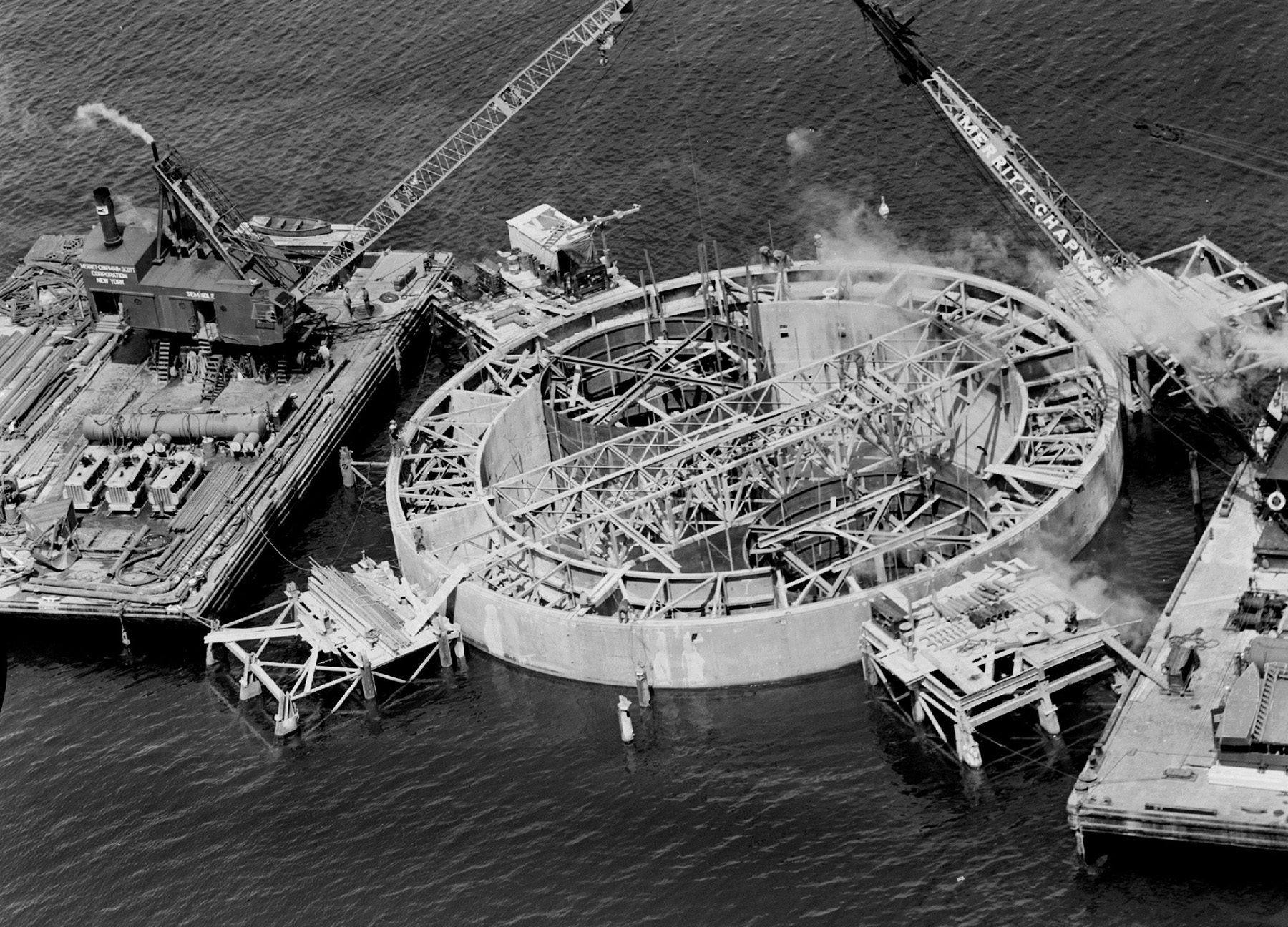
According to Nowack, another hurdle Steinman had to overcome was ice. There was concern that the ice that flows through the straits during the brutal Michigan winters could push over the suspension span’s piers. She says Steinman designed the bulk of the concrete for the piers to be 10 ft below the water surface, so that when ice flowed through at the surface, it had a smaller cross section to push against. He also built single piers instead of double piers so that ice couldn’t get jammed between them, and he designed the piers to be round wherever possible.
Lastly, the concrete anchorages to which the cables connect were hollowed out so that “the weight of the anchorage block is reduced to a minimum so as to lighten the load on the deep foundations as far as possible,” according to the 1951 report.
Construction began in 1954 with, as MDOT recounts, the construction of the bridge’s main piers: “Enormous steel caissons were sunk into the mud under the straits and then driven to bedrock. After removing all the mud and loose rock, two reinforced concrete piers, which extended to bedrock, more that 200 feet below the water’s surface, were poured,” according to the MDOT website.
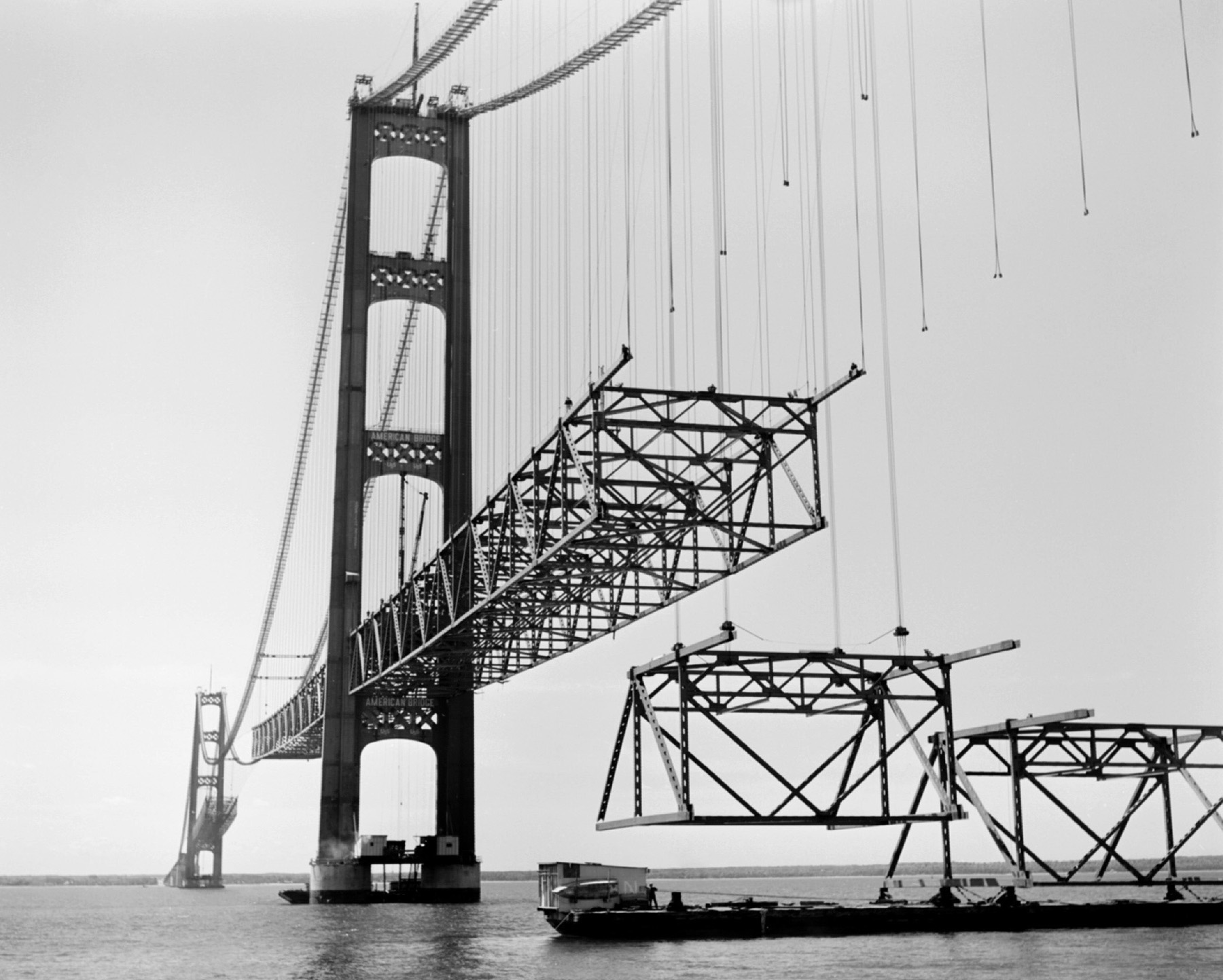
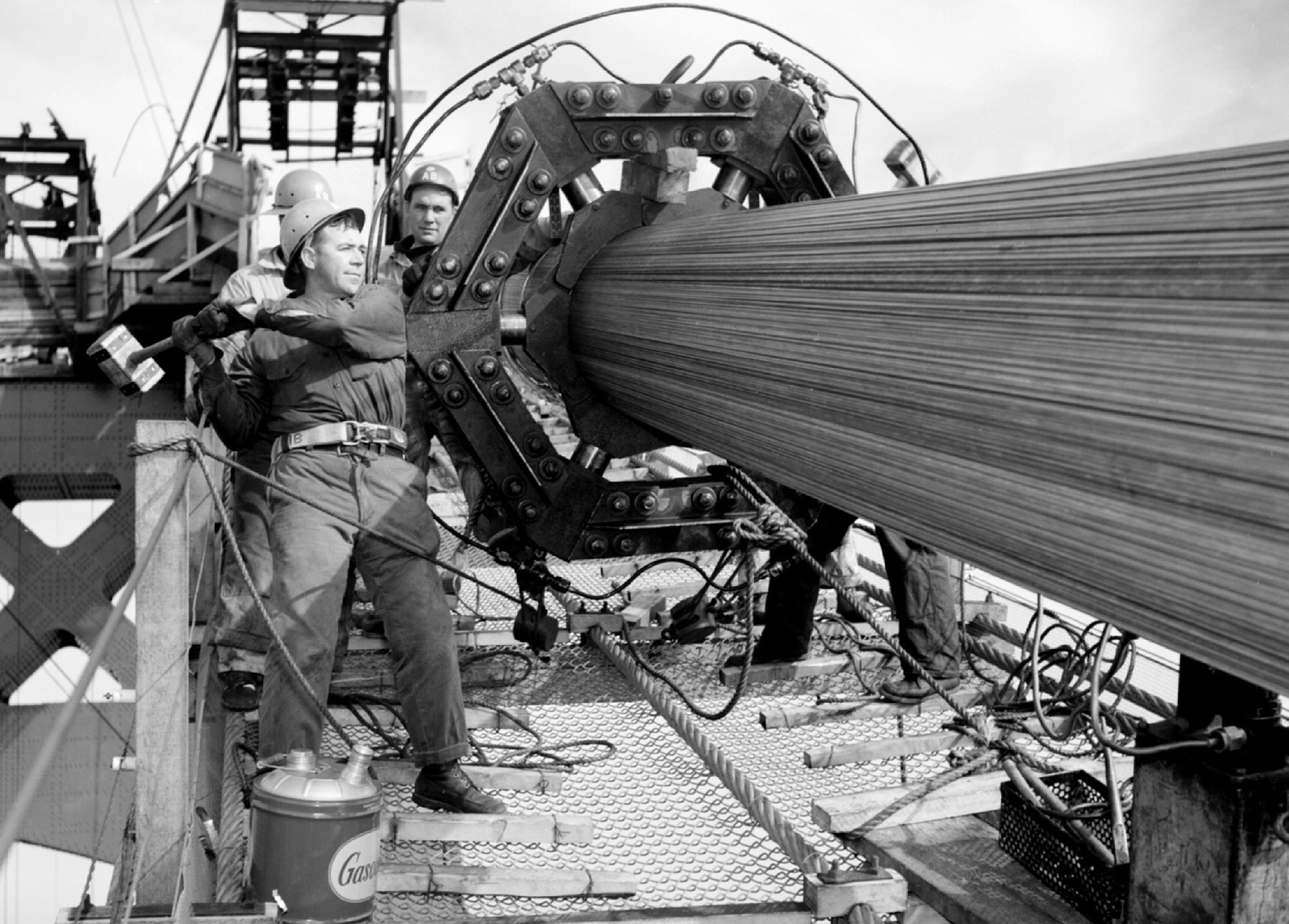
American Bridge fabricated and erected the bridge. The 7,400 ft, three-span suspension segment includes a 3,800 ft main span. The bridge also includes 35 deck truss spans and 14 steel-plate girder spans. The main cables are 24.5 in. in diameter, made from 37 air-spun, parallel wire strands of 340 wires each, and are connected to two 552 ft tall towers. According to the bridge authority, the height of the roadway at midspan is approximately 200 ft above water level. The vertical clearance at normal temperature is 155 ft at the center of the main suspension span and 135 ft at the boundaries of the 3,000 ft wide navigation channel. The deck at the center span was designed to move up to 35 ft east or west in high winds — without twisting.
The remaining piers were built in 1955, and in 1956 the main cables were strung and the 28 truss spans that made up the approaches were built.
Nowack explains that the bridge builders used an innovative concrete method called Prepakt concrete, which allowed them to place coarse aggregate into forms, then place grout tubes within that coarse aggregate, and then use the tubes to pump cement and fine aggregate in among the coarse aggregate, creating concrete. This way builders didn’t need big mixers and could create the concrete more quickly.
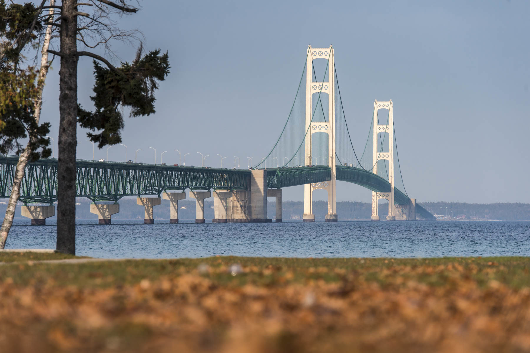
The bridge opened to traffic on Nov. 1, 1957. While the main span has long since been surpassed by a few dozen bridges, Mackinac’s total length of 26,732 ft makes it one of the longest suspension bridges in the world to this day. The Mackinac Bridge was named a Historic Civil Engineering Landmark by ASCE in 2010.
The bridge has remained remarkably durable. In 2019, more than 4.2 million vehicles, or about 11,000 per day, crossed the structure. The bridge hasn’t required any retrofits since opening, says Nowack. “We’re basically just keeping things up,” she says. Spot-cleaning crews clear debris that gets into the open grates of the roadway and repair small cracks that form because of thermal expansion and contraction. The main cables are constantly repainted to keep water from infiltrating them and corroding the wires.
The bridge has never been entirely stripped and repainted, though its towers have in recent years. By the end of this year, the entire bridge will have been stripped and repainted, its lead paint replaced by more environmentally friendly zinc.
When asked why it took so long for such work to be required, Nowack pointed out that the Tacoma Narrows Bridge debacle served as a sign that suspension bridges, especially in that era, were pushing engineers to the limits of their abilities. And Steinman, she says, had learned from this and his own experiences. “He implemented some of this stuff,” she says.
“This was one of the last bridges he worked on,” Nowack adds. “He learned in his life span … how to do it right.”
T.R. Witcher is a contributing editor to Civil Engineering.
This article first appeared in the November/December 2021 issue of Civil Engineering as “Taming the Wind: The Mackinac Suspension Bridge.”