By Derek M. Beaman, P.E., S.E., Tom Meyer, P.E., S.E., and C. Stephen Pool, P.E., S.E.
Tasked with completing the Las Vegas Convention Center’s 1.4 million sq ft expansion in record time, the project team developed and implemented tailored structural solutions within a hyper-fast-track schedule to complete the design and construction in only 36 months, setting a new bar for construction achievement within the market.
More than 60 years ago, Las Vegas civic and business leaders set out to draw more visitors to the city’s hotels and casinos during offseasons and quiet weekdays by building a convention center on the site of a former horse and automobile racetrack. By today’s standards, the original convention center, which opened in 1959, seems quaint — a 6,300-seat silver-domed rotunda and a 90,000 sq ft exhibit hall — but it got the job done and, perhaps unknowingly, set the stage for the future.
To keep up with ever-growing demand, the city has renovated and expanded that original convention center eight times over the past six decades. Those efforts have been rewarded with an annual streak that eclipsed the 25-year mark in 2019: Las Vegas named as the top trade show destination in North America by the Trade Show News Network.
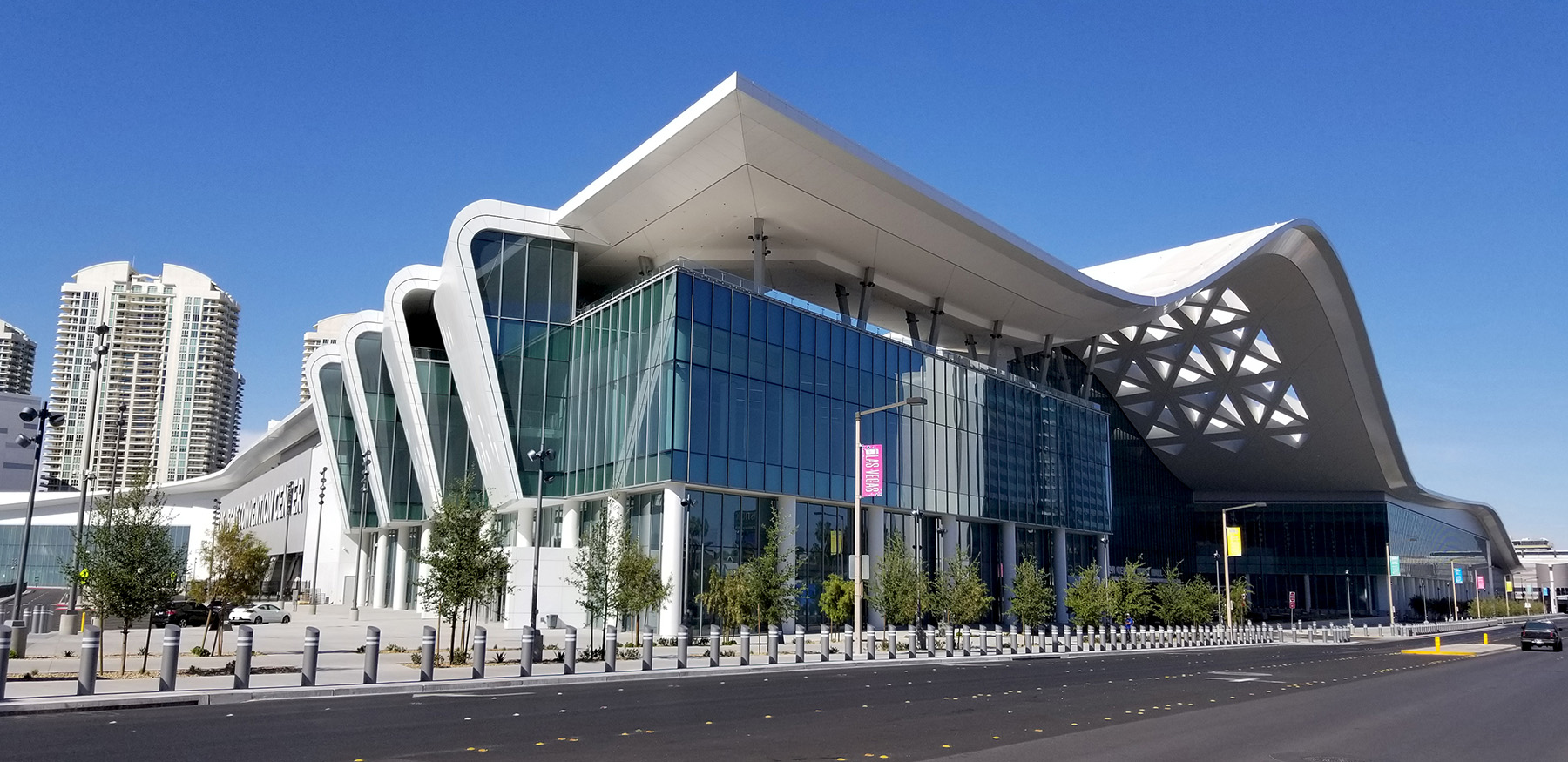
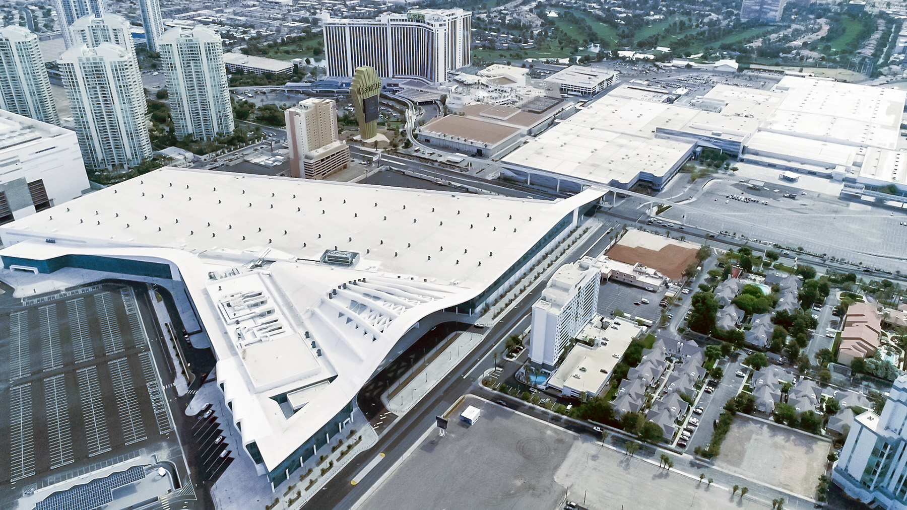
That trend continues today, with the Las Vegas Convention and Visitors Authority recently completing a $980 million, 1.4 million sq ft West Hall expansion project. The new facility is west of the existing center — across Paradise Road, on land previously occupied by the Landmark Hotel and Casino and the Riviera Hotel and Casino. Design for the new space commenced in January 2018 and construction was completed in early 2021.
The project added a 600,000 sq ft exhibit hall, 210,000 sq ft of concourse space, 150,000 sq ft of space for meetings and multipurpose activities, a 14,000 sq ft outdoor terrace spacious enough for 2,000 visitors, and more than 500,000 sq ft of back-of-house service and support space. With this expansion, the LVCVA aspires to bolster the city’s economic future and retain its status as the top trade show destination, a safe bet considering it will push the convention center’s available exhibit space past the 2.5 million sq ft mark, more than 28 times larger than the original building’s offering.
The ultimate challenge
Projects of this size face unique challenges, and the Las Vegas Convention Center’s expansion was no exception. In this case, the most significant challenge was an aggressive schedule.
The LVCVA wanted the expansion project completed in time for CES — one of the largest trade shows in the United States — in January 2021, which ended up being held virtually due to the pandemic. After selecting the design team in fall 2017, there were just three years to design, construct, and finish the ambitious project — a feat that to the authors’ knowledge had never been achieved in North America for a convention building of this size and complexity.
Creative engineering solutions, coupled with seamless collaboration between the owner, design team, and construction groups, were required to meet such an aggressive, fast-track timeline.
Shortly after its selection in early 2018, the construction manager at-risk, TMH (a joint venture between Turner Construction Co. and Martin-Harris Construction), outlined an overall construction timeline of approximately 27 months, with 15 of those months devoted to structural construction. Both durations are approximately 25% shorter than other comparably sized convention center expansions. To complete the project in time for CES, foundation installation needed to begin no later than September 2018 — just eight months after the design team held its kickoff meeting — and superstructure construction needed to begin just five months later.
The team developed a hyper-fast-track structural design schedule that centered on the issuance of early procurement, permit, and construction packages. Twelve early structural packages — including five steel procurement, mill order, and detailing packages and seven structural permit packages — needed to be issued by December 2018. Successfully delivering so many structural packages so early in the overall design schedule required extensive collaboration and communication between all members of the project delivery team as well as timely decisions by the LVCVA.
Magnusson Klemencic Associates, the prime structural engineer for the project, developed a three-tiered strategy to meet the schedule. Working closely with the architectural and owner teams, MKA studied the programmatic, geometric, and design parameters while simultaneously evaluating and presenting options for key issues, such as column spacing and rigging configuration, to guide decision-making.
With that knowledge, MKA next worked with TMH to evaluate structural system options and identify the best balance between cost, constructability, and schedule. MKA then developed and managed a detailed list of, and schedule for, the information required from the owner, TMH, and the design team to expedite structural design progress.
Ultimately, the execution of this strategy resulted in all 12 early structural packages being issued on time.
Structural system selection
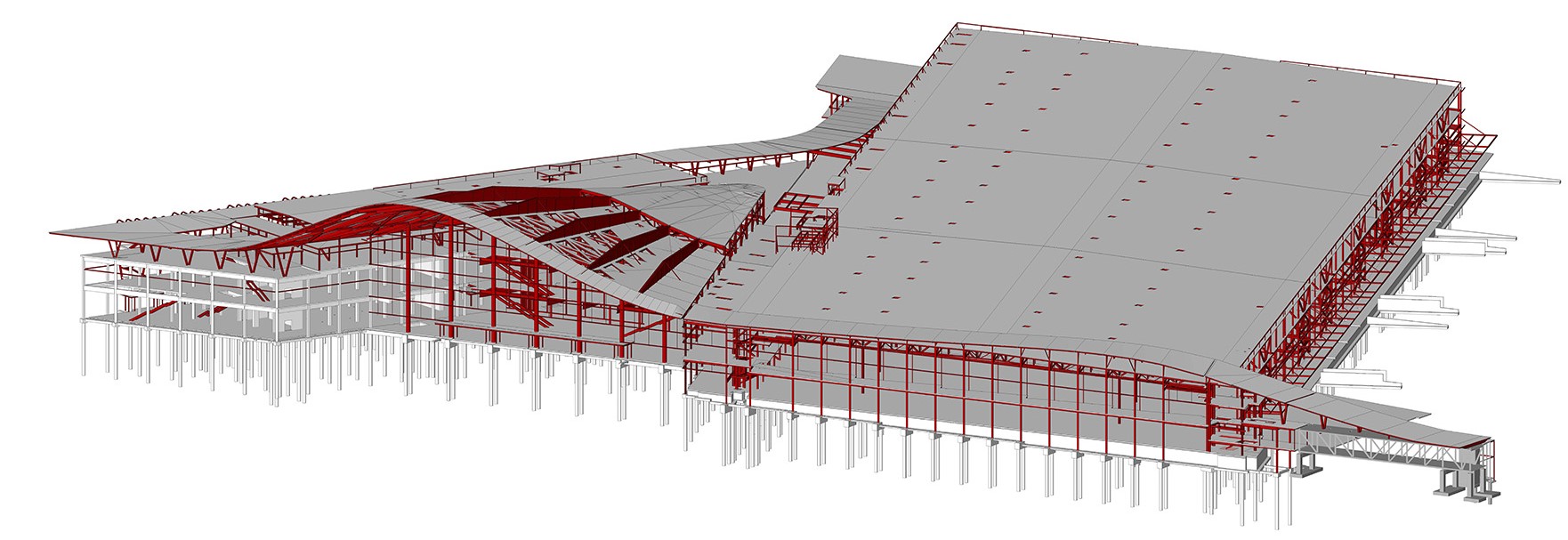
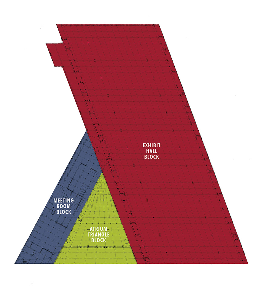
At first glance, the structure for the West Hall looks like one holistic building. However, it comprises three unique and significant subcomponent buildings or blocks. They are:
- Meeting room block: 85 ft by 780 ft and including most of the meeting and multipurpose spaces.
- Exhibit hall block: Diagonally oriented, 1,325 ft by 580 ft, including the hall, its concourse, and support spaces.
- Atrium triangle block: Roughly 350 ft by 390 ft and including meeting and multipurpose spaces as well as the grand entrance lobby and its signature roof.
Each block demanded tailored, optimized structural systems, the selection of which carefully considered all design, construction, performance, and schedule objectives.
For the three-level meeting room block, a vertically stacked combination of structural systems was implemented. The design team employed a mild-reinforced, cast-in-place concrete framing system that allowed superstructure construction to begin immediately after completion of the foundation and without the need for long-lead procurement or fabrication components. Concrete slabs, typically 12 in. thick, span 30 ft between concrete beams. The beams, typically 60 in. deep, span up to 75 ft between columns to create the necessary clearances for the meeting room spaces.
Above level 3, where the clear spans increase up to 120 ft, the system transitions to a more cost-effective steel option. At the long-span roof condition above a 15,000 sq ft, column-free meeting room, truss depths were set at 10 ft to maximize prefabrication and erection efficiency.
For the four-level exhibit hall block, the critical link to achieving hyper-fast-track construction was in the selection of the ideal roof framing system. Seven column configurations were evaluated. To balance speed of construction, functionality, attendee experience, and the significant steel tonnage and cost premiums associated with extreme long-span options, the design team selected a 90 ft spacing column layout with a 270 ft center span.
Dictated by the need for erection speed, the framing layout maximized the use of secondary trusses, with their prefabrication and shipping efficiencies, and minimized the use of site-assembled primary truss girders. Supporting the 3 in. perforated (for acoustics) steel roof deck and wide-flange infill roof beams, secondary trusses — which are 10 ft deep and spaced 30 ft on center — span 90 ft between tapered-depth truss girders.
Although the 27 ft deep truss girders could not be prefabricated because of shipping limitations, careful coordination of the splice locations with TMH and the erector allowed the girders to be efficiently erected in three pieces without the cost or schedule impacts that accompany the use of temporary shoring columns. With a 42 ft clear height to the bottom chord of the truss girders, a truly world-class exhibit hall space was created.
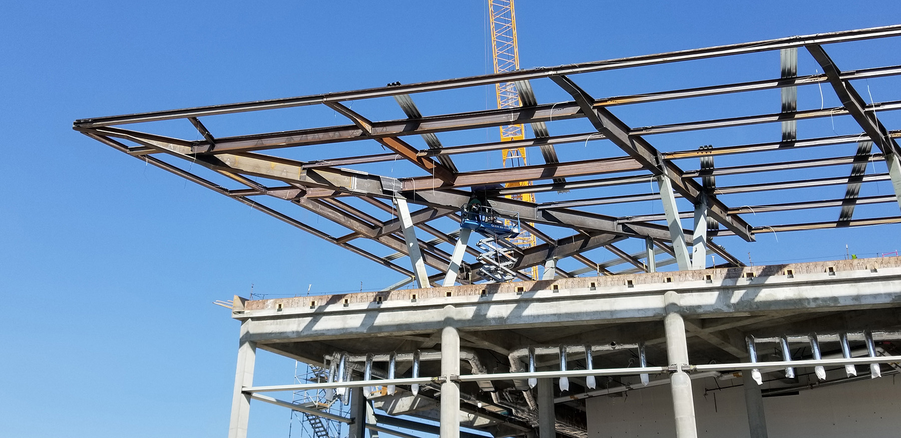
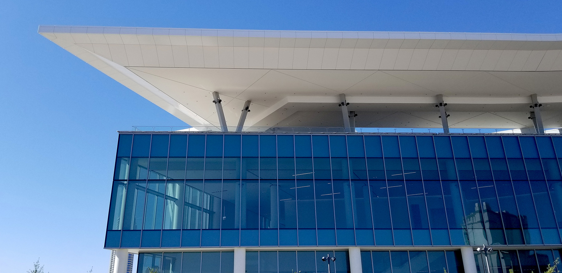
The atrium triangle block’s glass entry wall measures 350 ft wide and 125 ft tall. It is covered by a 117,000 sq ft signature roof that cantilevers 125 ft to provide an awe-inspiring sunshade for arrivals and departures in the outdoor space at ground level, delivering the “wow” moment the owner sought in the expansion.
To achieve the heroic cantilever spans in the atrium, tapered, built-up steel rib girders were radially arrayed over each of the seven steel-pipe columns located just inside the lobby wall. The girders, made up of horizontally oriented wide flange top and bottom chords, and steel plate webs, are 16 ft deep at the point of maximum flexure above the columns and taper down to 12 in. at the southern tip of the cantilever, depths carefully selected to make the most of prefabrication opportunities and achieve the thin architectural profile at the leading edge.
Although the obstacles posed by the geometry and spans of the gravity framing system were significant, they were surpassed by the challenge associated with the development of the optimal lateral-force-resisting system. Wedged between three separate and independent building structures, the floor and roof elements of the atrium triangle block had to be adequately braced without violating the separation between those three buildings. Rather than incur the cost and schedule impacts associated with an independent lateral-force-resisting system, a strategy was implemented whereby the adjacent building blocks resisted the loads in the atrium block.
The steel-framed floors connect to the concrete structure of the northern meeting room block, making use of its concrete shear walls to resist most of the lateral loads, augmented only by a single steel buckling-restrained braced frame at the eastern edge. Lateral support for the roof, however, comes from the southern exhibit hall block. To provide the necessary vertical support for the roof along its western edge — yet avoid any lateral load transfer between the roof and the meeting room block structure — slide bearings were placed at each of the 14 interfaces between the two systems to allow independent lateral movements of up to 14 in. in all horizontal directions.
A ribbon to tie it together
Architecturally interconnecting all the elements of the expansion is a continuous “ribbon” roof element located along the west and south sides of the overall building. At most of the conditions, the framing for this roof element was created by either a straightforward cantilever of the primary roof framing or over-framing above the primary structural roof using steel posts, beams, and girders to support the roof deck.
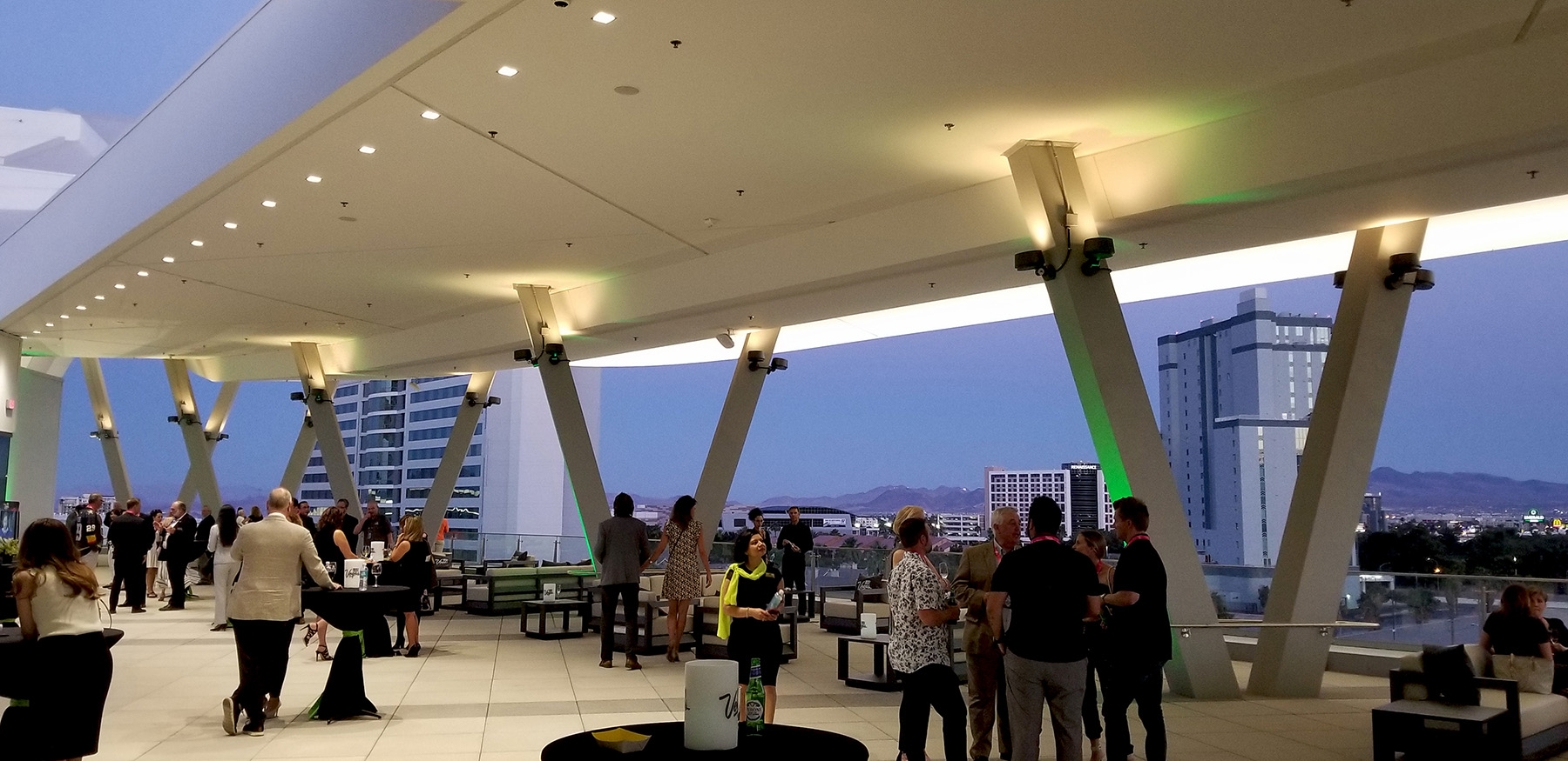
At several locations, however, a “flying ribbon” condition was created. At the south end of the meeting room block, for example, the ribbon roof floats above the outdoor terrace space located on level 3 to provide shade and enhance the patron experience in this signature space. At each location, steel V-shaped columns made up of 18 in. square, built-up steel tubes support tapered steel girders that cantilever up to 65 ft in each direction.
One of the most complex flying ribbon conditions occurs at a pedestrian bridge across Paradise Road. Although the bridge was an existing structure constructed as part of a past addition, the original design did not consider the loads imposed by a future roof element so essential to completing the architectural expression of the West Hall expansion.
The existing bridge structure, comprising interstitial steel trusses that span the road and are supported by concrete moment frame bents on either side, was rigorously analyzed for its ability to support the new loading condition. To maximize schedule efficiency and eliminate the need for any road closures, the existing structure was strengthened as needed rather than replaced. By adding retrofits such as fiber wrap confinement on the concrete beams and columns, strengthening truss chords and roof beams, and replacing select roof beams, a structural system with the capacity to support the swooping ribbon roof was realized.
The ribbon roof creates an architectural expression that puts a beautiful bow on the overall design of this massive facility.
Poised for success
Completing a project of this size, scope, and quality was no small feat. Add to the mix a hyper-fast-track schedule to design, build, and complete the building, and the challenge was even more daunting.
Creative engineering solutions executed within a collaboratively developed schedule allowed the Las Vegas Convention Center expansion project to be completed on time. Tailored structural systems optimized for each component of the building — designed and delivered in multiple procurement, permit, and construction packages — were essential to meeting the unprecedented fast-track schedule and achieving the overall project goals.
The building opened its doors to the public in a ribbon-cutting last summer, positioning the Las Vegas Convention Center for the future as it strives to remain the top trade show destination in North America for years to come.
Derek M. Beaman, P.E., S.E., is a senior principal, Tom Meyer, P.E., S.E., is a principal, and C. Stephen Pool, P.E., S.E., is a senior associate in the Seattle office of Magnusson Klemencic Associates.
Project Credits
Owner’s representative: Miller Project Management, Las Vegas
Construction manager-at-risk: TMH joint venture: Turner Construction Co., New York City/Martin-Harris Construction, Las Vegas
Architectural design team: TVS Design, prime architect, Atlanta; TSK Architects, Henderson, Nevada; Simpson Coulter Studio, Las Vegas; KME Architects, Las Vegas; Carpenter Sellers Del Gatto Architects, Las Vegas
Structural engineering team: Magnusson Klemencic Associates, Seattle, prime structural engineer; Poggemeyer Design Group, Las Vegas; Sigma Engineering Solutions, Las Vegas
This article first appeared in the July/August 2022 issue of Civil Engineering.