By Thomas Murphy, Ph.D., P.E., S.E., M.ASCE, Todd McMeans, P.E., and Andrew Keaschall, P.E., S.E., M.ASCE, F.SEI
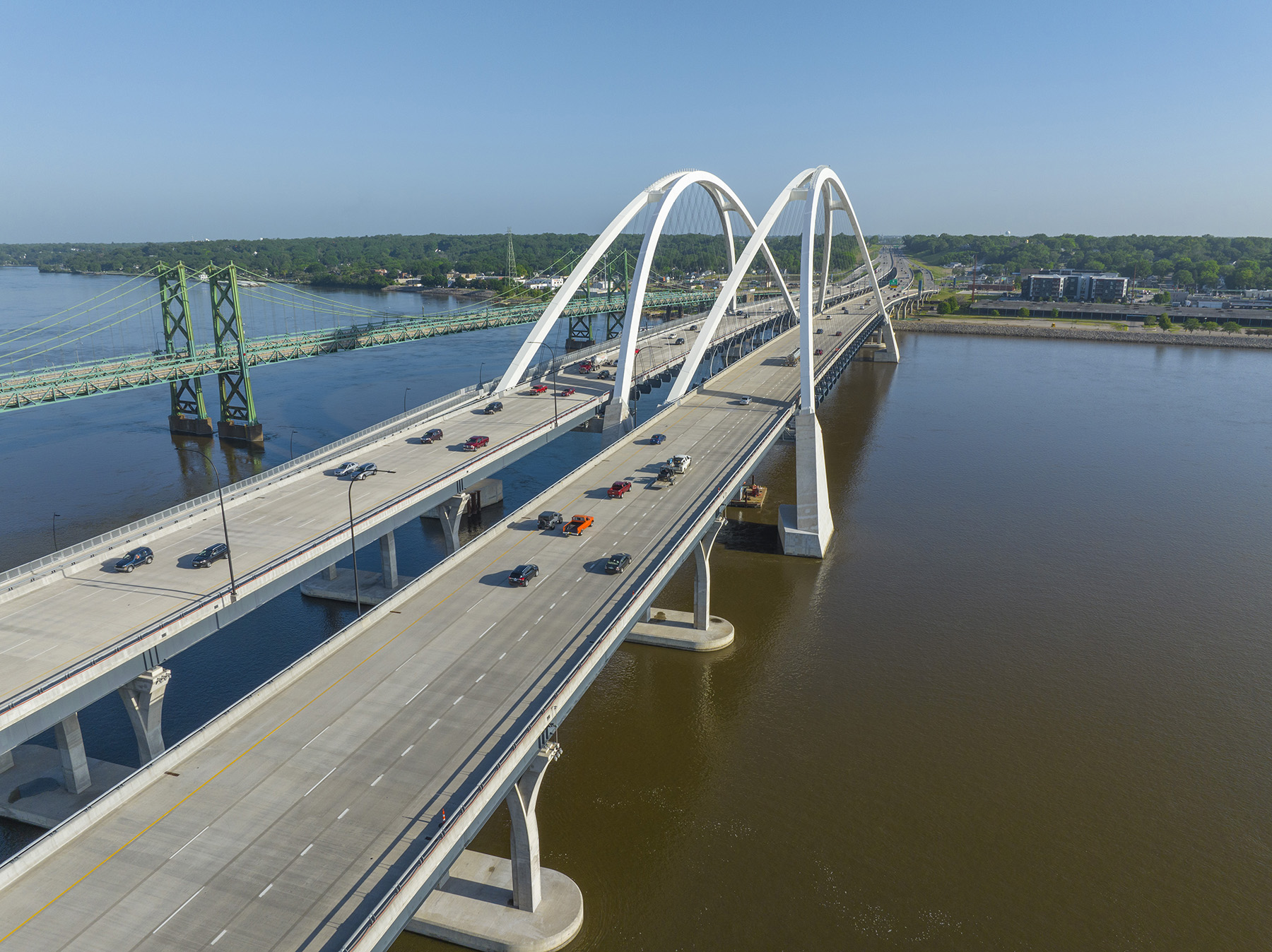
The Interstate 74 Mississippi River Bridge project improves commuter and pedestrian connectivity in a region of Illinois and Iowa known as the Quad Cities. The project comprises a new twin-span bridge that traverses the river, linking the two states, as well as reconfigured interchanges and revamped roadways in the region.
The area of the country known as the Quad Cities has long been a key transportation hub for national commerce: first as a port on the Mississippi River, then as a critical railroad crossing (and the site of the famous court case in which then-lawyer Abraham Lincoln defended the railroad’s right to cross the river), and finally as an integral part of the nation’s highway system in the Midwest. For the Quad Cities region — Bettendorf and Davenport in Iowa and Rock Island, Moline, and East Moline in Illinois — that integral link is Interstate 74, which has been carried across the Mississippi by two iterations of the I-74 bridge.
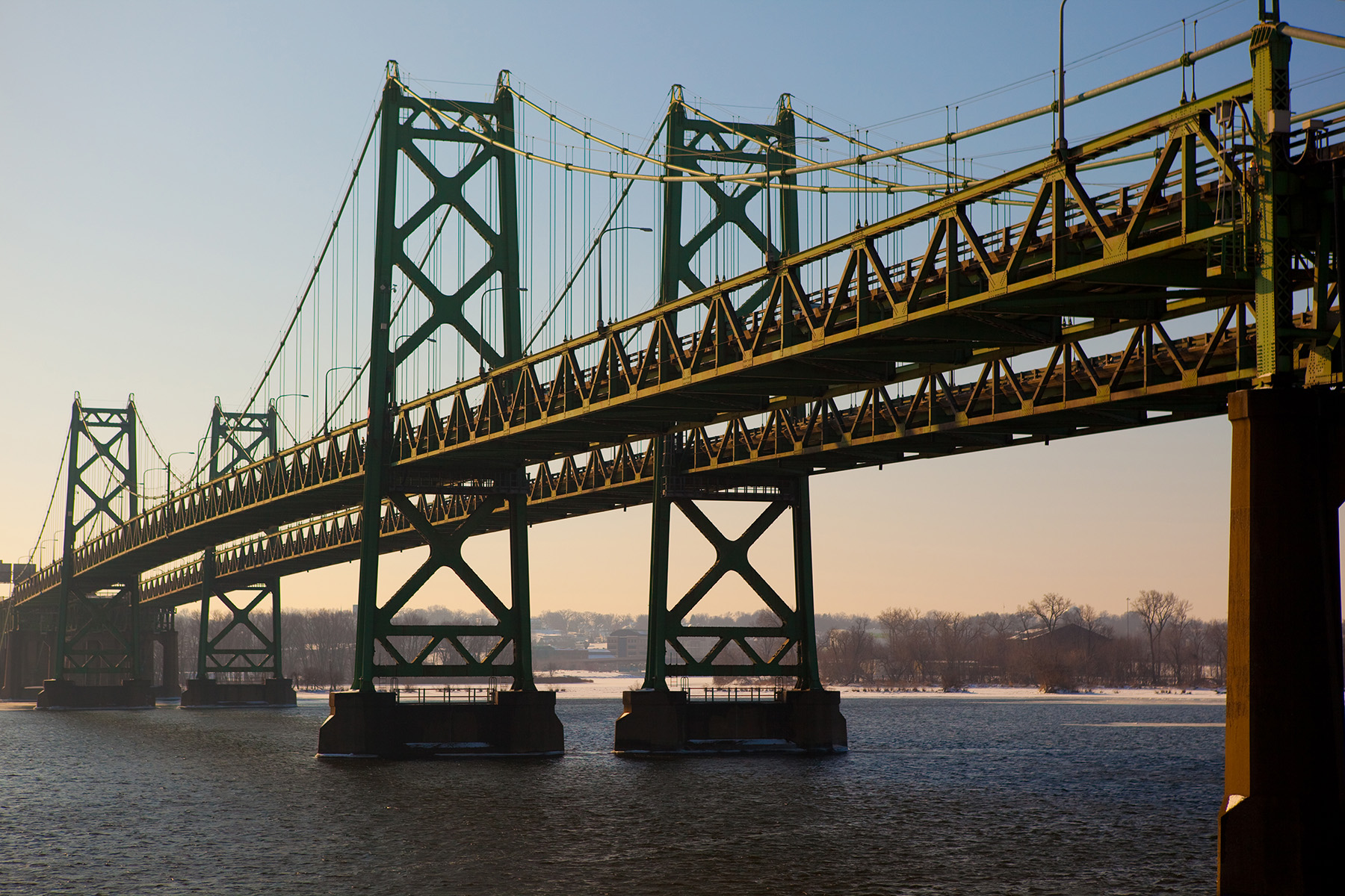
The first, a twin-span suspension bridge built in the 1930s (westbound to Iowa) and the 1950s (eastbound to Illinois), was a shoulderless, four-lane bridge (two lanes per span). Because the lanes were substandard in width and there were no shoulders, cars traveled right next to the stiffening trusses — an uncomfortable driving experience for some. As the Quad Cities population increased, it became evident that traffic demands would soon outgrow the bridge’s capacity and it would need to be replaced.
In the 1990s, the Iowa and Illinois departments of transportation, in conjunction with other stakeholders, initiated the I-74 Iowa-Illinois Corridor Study, the goal of which was to determine how to improve traffic conditions in the region, increase mobility, and provide a more efficient, environmentally friendly, and aesthetically pleasing route to link the Quad Cities.
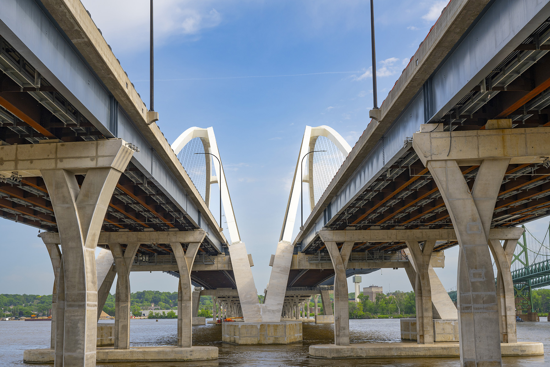
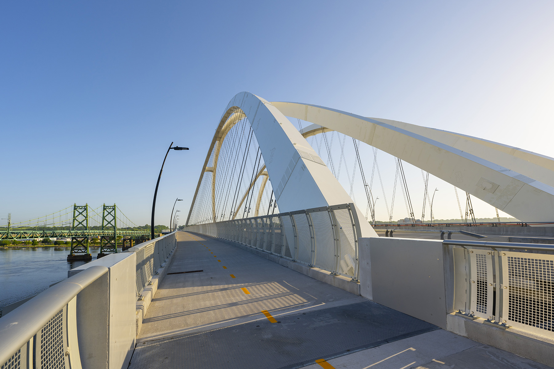
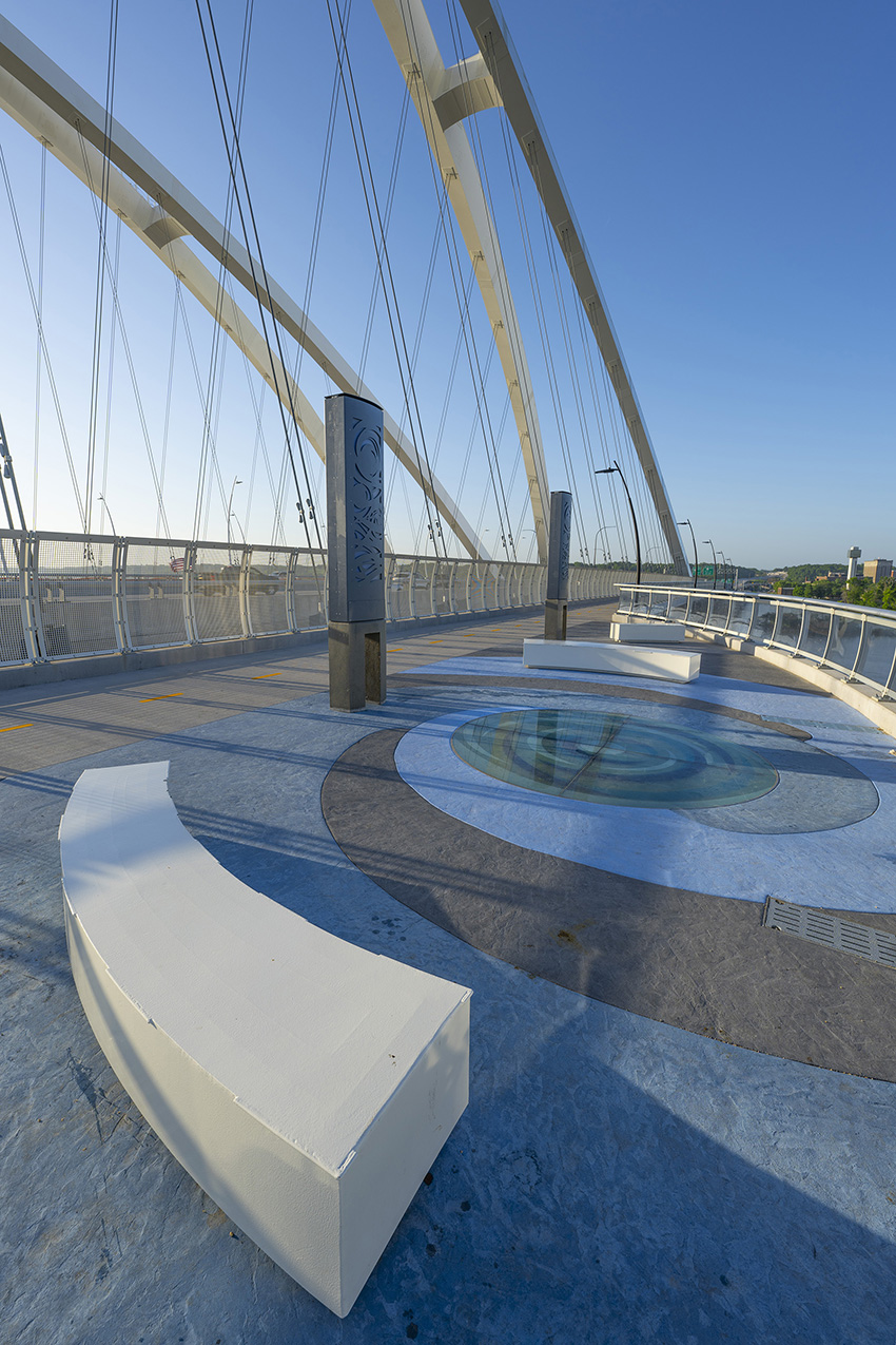
From that initial study and other initiatives has come the second I-74 bridge — a twin-span, basket-handle, through-arch structure that comprises four lanes of traffic per bridge with two full shoulders on each side of the travel lanes, more than doubling traffic capacity at the river crossing. Although they look like twins, the spans have a significant difference in that the eastbound span also carries a 14 ft wide bicycle and pedestrian path that cantilevers downstream of the arch rib. At midspan there is a wide overlook with benches and artistic features, including a glass oculus in the floor.
The overall I-74 project includes reconstruction and reconfiguration of almost 8 mi of roadway and bridges in Iowa and Illinois delivered through multiple design-bid-build construction contracts. These changes include new lengths of viaduct in the urban areas of Bettendorf and Moline to the north and south of the Mississippi, respectively. Additionally, I-74 was realigned to remove a curve and improve the interchange geometry.
Founded on bedrock
Bedrock is close to the surface in this stretch of the river, so the design team opted to use the bedrock to resist horizontal forces caused by the arches instead of relying on the tie girders of a tied arch. This echoes the same approach employed for the existing suspension bridges, which similarly anchor the horizontal forces from the suspension cables into bedrock. The eastbound and westbound lanes on the new bridge are carried by separate superstructures and substructures. However, they share a common foundation along the centerline of the alignment.
For the new bridge, the design team needed to develop a foundation that would efficiently transfer the arch thrust to the bedrock. Relying on only a spread footing keyed into rock presented several challenges, including the ability to effectively seal a cofferdam for rock excavation with little to no soil overburden in the river and ensure adequate force transfer through bedding planes.
Instead, the solution implemented was to use drilled rock sockets to transfer the thrust as a shear force. The short height of the sockets above the riverbed limited the magnitude of bending moments, permitting a more economical design.
Arch stability
The conceptual design of the spans called for steel arch ribs with minimal bracing connecting them in a basket-handle configuration. The ribs of each bridge are connected at only three locations: the two intermediate struts on either side of midspan and the main strut directly at the arch crown. The main strut in turn is divided into two substruts with a gap between them. All struts provided vierendeel-style bracing, acting in bending rather than in tension and compression.
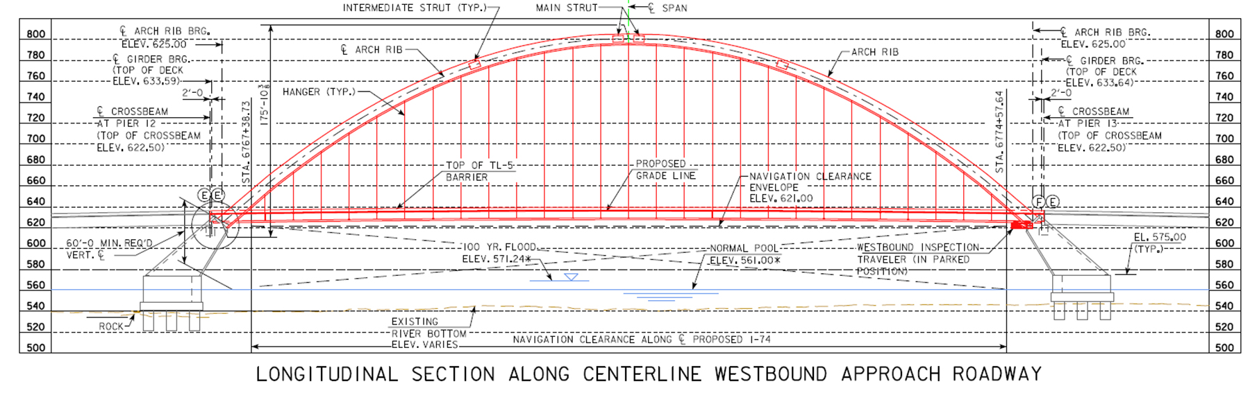
The river crossing is more than 3,300 ft long with an almost 800 ft navigation span, requiring a signature, long-span structure. Given this, the design team carefully evaluated the stability of the arch ribs to ensure adequate performance under typical and rare loadings. Unlike a tied arch, for which buckling in vertical mode is extremely rare, a true arch without a tie can be susceptible to buckling vertically and laterally.
A two-step approach was adopted that consisted of using refined analyses to determine the elastic buckling modes and capacities from which averaged effective length and radius of gyration values for the arch rib system as a whole could be derived. These values were then used in the American Association of State Highway and Transportation Officials design equations for compression members to determine the ultimate capacities, including the effects of residual stresses and initial imperfections.
The effect of moment magnification also needed to be determined. Because of the large number of load combinations that must be investigated to satisfy AASHTO design specifications, linear elastic analyses and the use of superposition are desirable for an efficient design process. In contrast, the use of geometrically nonlinear analyses allows for an accurate determination of the magnification of moments that occur in compression members when subjected to significant deformations.
The design team employed a hybrid approach in which critical load combinations were analyzed with geometrically nonlinear analyses, and the resulting magnifications of the moments were then determined by comparing them with the results of linear analyses. The controlling magnification factor was then applied to the results of linear analyses to determine the design force effects for the arch spans.
The arch ribs
The arch ribs consist of welded steel box sections and in general have a single longitudinal stiffener on the top and bottom flanges and two longitudinal stiffeners along both webs. Near the base of the arch the number of stiffeners increases. The width of the box section ribs is constant at 6 ft, while the depth varies from 12 ft at the bases of the arches to 9 ft at the crown. To keep the weight of the field pieces manageable, ASTM A709 HPS70W steel was used. The 70 ksi yield strength of this material allowed for reduced plate thicknesses, which in turn reduced the weight of the sections as well as the size and cost of the box section welds.
The bolted field connections were designed to carry all loads through the bolts and do not rely on bearing of the plate ends to transfer the compression loads.
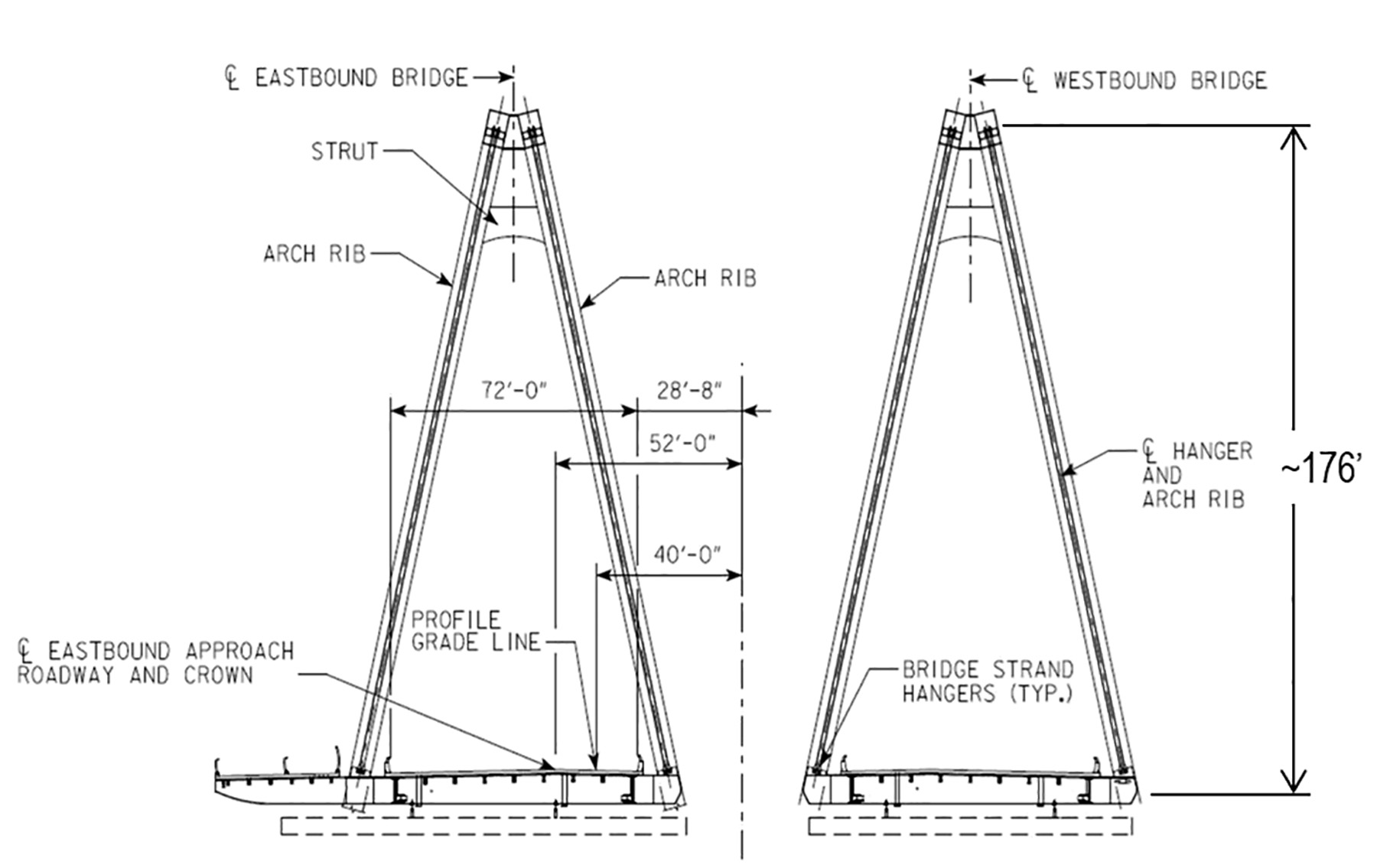
To facilitate construction and inspection, the design team added an access walkway system inside the arch ribs. The ribs are inclined toward each other approximately 13 degrees from vertical, which, when combined with the natural inclination of an arch rib, created a difficult interior surface to walk on that could be disorienting to inspectors.
The access system provides a walking surface that is level transversely so that inspectors and others can safely maneuver throughout the length of the arch ribs. Ladders and handholds are provided where the hangers are anchored within the arch ribs, enabling easy access across these congested points.
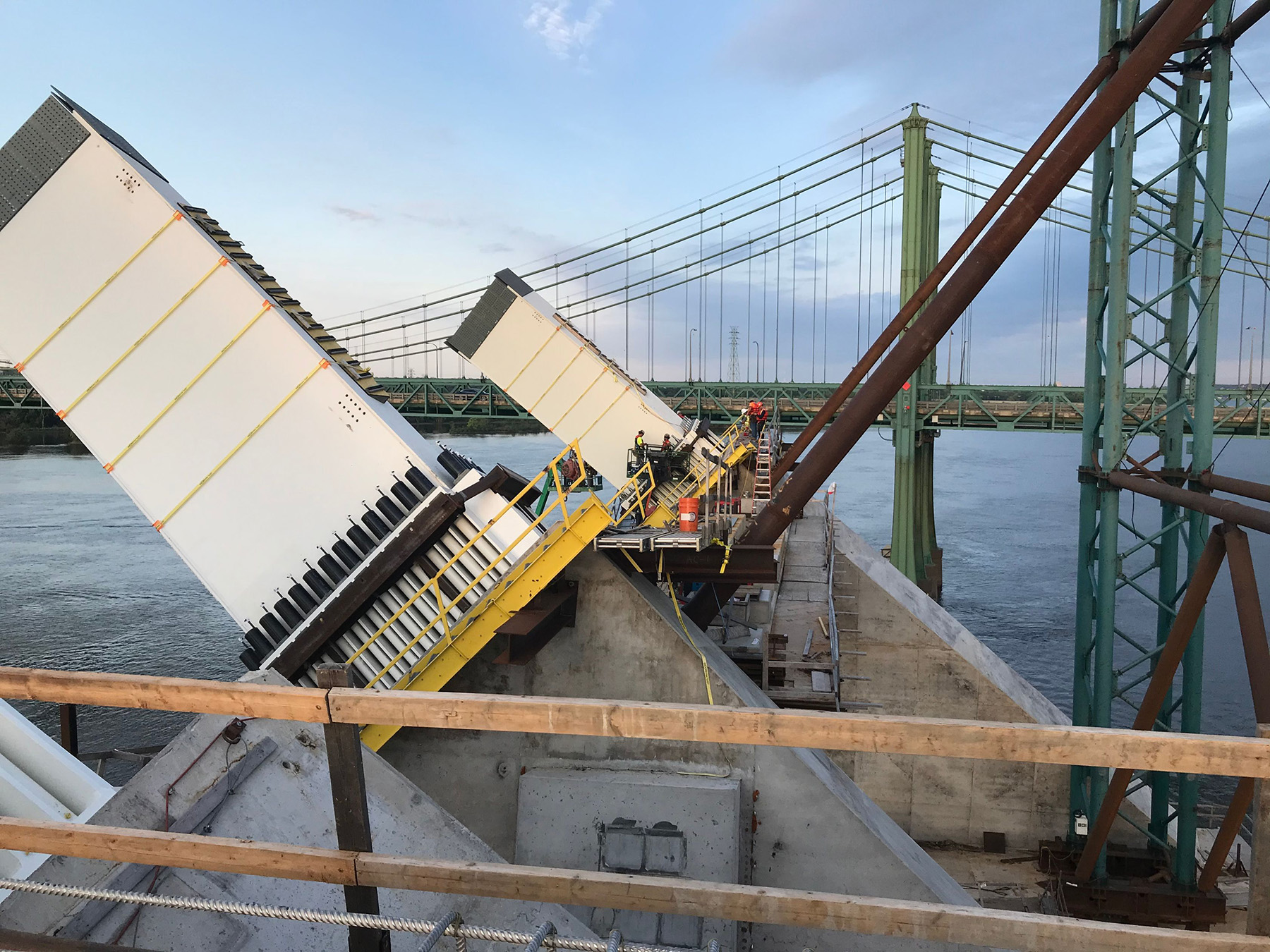
At the ends of the arch spans, the steel arch ribs transition to concrete ribs, which directly connect to the foundations. The steel-to-concrete connection was identified as a key location where durability needed to be carefully evaluated. The arches are of the fixed-end type, which means they transmit moments in all directions at the end connections in addition to the arch thrust.
These demands are accommodated by using prestressed anchor rods that pretension the steel base plate at the end of the arch ribs to an embedded steel plate in the face of the concrete rib. As these rods would be very difficult to inspect in the future — and even more difficult to replace should corrosion ever occur — the decision was made to use a high-strength, stainless steel material capable of being prestressed for the anchor rods.
The Iowa DOT undertook a research project during the final design phase to evaluate candidate materials and determined that the stainless steel duplex grade 2507, with a minimum yield strength of 116 ksi, was the best choice. The rods are 3 in. in diameter; 48 are used at the base of each arch rib. In addition to the rods, the anchor and coupling nuts are also made from 2507 duplex stainless steel.
Lateral loads and floor system
The cantilevering of the multiuse pedestrian-bicycle trail outboard of the eastbound arches, in combination with the basket-handle configuration, resulted in unusual structural behavior. The location of the trail results in one arch rib — and the hangers connecting it to the floor system — carrying more load than the other. Due to the inclination of the hangers in a basket-handle arch, this results in more lateral load being applied to the deck from one line of hangers than from the other, or in other words, a net lateral load due to dead load applied to the floor system.
There is an equal and opposite lateral load applied to the arch ribs, as the system is self-equilibrating. However, the result is that the lateral bracing of the floor system is part of the primary gravity load system, and the wind tongues that transmit the lateral loads from the floor system to the substructure carry a permanent load in addition to variable wind loads.
The steel floor system of the arch bridges consists of floor beams that span between the hangers and, in the case of the eastbound bridge, cantilever past the hangers to support the trail and overlook. These floor beams support the longitudinal elements, which consist of deep edge girders and shallow stringers. The edge girders provide additional stiffness to the global system and redistribute hanger loads in the event a hanger is removed or damaged.
All components of the floor system are composite with the concrete deck, which necessitated placement of the top flanges at a common elevation, and steel connection details that provide for continuous moment connection where the edge girders and stringers cross the floor beams. The spacing of the floor beams is such that they are classified as fracture-critical members.
To mitigate this, HPS70W steel was used for the bottom flanges of the floor beams, and project-specific impact toughness requirements were included to ensure these key elements exhibited superior fracture toughness.
Wind loads
Wind tunnel testing indicated the potential for undesirable vortex-induced oscillations in strong winds. A mitigation system consisting of winglets, arranged along the leading edge of the westbound bridge, addresses this issue. For the eastbound bridge, the cantilevered multiuse trail effectively acts as a winglet, so no additional mitigation was required.
The winglets span between floor beams and employ the same airfoil shape as the wings of a World War II B-17 bomber. Because the westbound bridge was constructed first, winglets are included on both sides of the bridge. To prevent wind vibration of the structural strand hangers, Stockbridge-style dampers were used. These dampers are located on each strand of the hangers near deck level. Additional dampers were installed on select hangers within the arch ribs to prevent vibration due to parametric excitation from floor system vibrations.
Design details
The team included multiple design details to improve the durability of the bridge, with the goal of extending the service life of 100 years. These include:
- A fluoropolymer coating system on the arch ribs for enhanced aesthetics and durability.
- All stainless steel reinforcement in the concrete deck and barriers.
- A maintenance waterline along the length of the floor system located below the bridge deck that makes it possible for workers to wash the steel components.
- Uncoated weathering steel in the floor system, with the exception of the fascia girders, which are painted with a fluoropolymer coating.
- A structural health-monitoring system for the floor system and arch ribs.
- The ability to replace any hanger on the bridge without significant traffic interruptions.
Coming together
The westbound span opened in November 2020, followed by the eastbound span in December 2021. The demolition contract to remove the original bridge is underway.
With a steady stream of pedestrian and bike traffic over the bridge, not to mention the drivers who no longer are subjected to an intimidating experience while crossing the river, the new I-74 bridge fulfills the vision for a safe, welcoming crossing that will take the legacy of the Quad Cities as a key transportation hub well into this century and the next.
Thomas Murphy Ph.D., P.E., S.E., M.ASCE, is the senior vice president and the chief technical officer, and Todd McMeans, P.E., is a senior vice president and project manager for Modjeski and Masters in Mechanicsburg, Pennsylvania. Andrew Keaschall, P.E., S.E., M.ASCE, F.SEI, is a senior vice president and the Illinois division manager at Alfred Benesch & Co. in Chicago.
Project credits
Owners: Iowa Department of Transportation, Illinois Department of Transportation
Designers: Alfred Benesch & Co., Chicago (substructure); Modjeski and Masters, Mechanicsburg, Pennsylvania (superstructure)
Construction engineering and inspection: HNTB, Kansas City, Missouri, and Minneapolis
Corridor manager: Wood PLC, Bettendorf, Iowa
General contractor: Lunda Construction Co., Black River Falls, Wisconsin
Erection consultant: Lucid Engineers, PC, Minneapolis
Erection engineer: McNary Bergeron & Johannesen, Broomfield, Colorado
This article first appeared in the November/December 2022 issue of Civil Engineering as “Quad Cities Connection.”
The name and location for the erection consultant, Lucid Engineers, PC, has been corrected. The editors regret the error.