By Brittany Huntsberger, P.E., M.ASCE
When it comes to designing transmission infrastructure over rivers, there is a lack of published guidance that takes into account extreme winds and floods. Nevertheless, engineers developed a robust plan for a replacement over the Rio Salado in New Mexico.
Nonstructural environmental events such as river scour and bank loss can lead to failures of critical transmission systems that cross rivers and streams. Hydraulic forces, including debris and flowing or expanding ice, can further contribute to foundation loads if the flow of floodwaters reaches the foundations. Earthquakes can cause liquefaction, which can lead to a loss of ground resistance and can increase the loads on the foundation because of lateral spread or down drag. Landslides, which can be triggered by earthquakes or other environmental factors, can also contribute to significant foundation loads.
Unlike the commercial building and transportation industries, the electrical transmission industry has little published guidance for designing structural foundations for transmission lines to address these events.
With such a lack of guidance, utilities often develop their own best practices and design guidelines from other, more established industries, such as building design and transportation. But nonuniform approaches to foundation design lead to significant variation among utilities and industry professionals, sometimes resulting in under- or over-designed transmission foundations.
The Deep Foundations Institute and ASCE are working together to create guideline documents for the transmission industry, and DFI has established the Electric Power Systems Foundations Committee to better understand the deep foundation needs of the electric power industry. Earlier this year, this committee published Design and Construction of Deep Foundations to Support Electric System Transmission Lines — State of the Practice Summary.
Similarly, ASCE is in the process of developing a comprehensive manual of practice (Manual of Practice for the Design of Overhead Line and Substation Foundations), which summarizes current foundation design practice to provide information that foundation engineers can use to make informed decisions on their projects. The document will present a wide range of guidance and discussion related to foundation analysis, design, and construction, and is expected to be completed in 2026. DFI’s load combination document is intended to complement the ASCE guidance for foundation design.
Based primarily on industry surveys, engineering judgment, industry knowledge from EPSF Committee members (some of whom are also members of ASCE), and industry professional reviews, the DFI summary identifies current industry shortcomings that warrant additional research and takes an important first step toward defining a unified industry approach.
Solid start
When designing foundations for transmission lines, geotechnical and hydraulic studies are needed to assess risk levels and provide data. Risk factors include local scour of subsurface soils around the foundation during high-flow events, long-term ground loss from various channel and bank conditions, and hydraulic forces on the foundation from flowing water and debris.
The geotechnical study must assess enough of the project area to represent various channel flow conditions, and subsurface samples must be taken at sufficient depth. Particle size analyses of the stream bed and soil classification are essential for determining the depths of the general bed degradation and potential impacts of local scour.
Hydraulic analysis often begins with a desktop study to review publicly available aerial imagery as well as topographical and flood maps, a study of the scour history from nearby bridges, and mapping state or local floodplain information with respect to each foundation location.
The likelihood of typical and unique scour conditions is also evaluated for a given site. A site visit is an important step in the design process to observe existing flow patterns and to visually estimate surface roughness (Manning’s roughness coefficient) and surface soil gradation, surficial soils, vegetation types, and other features required to provide critical information for hydraulic model development and scour analysis.
Several hydrologic routing methods can be used to develop channel flow properties. Distributed-flow routing is accomplished by using hydraulic routing models such as the U.S. Army Corps of Engineers HEC-RAS (Hydrologic Engineering Center’s River Analysis System). The HEC-RAS software is a depth-averaged numerical solver used to determine peak and normal flow-event properties such as water surface elevations, flow depths, and average channel velocities. A peak flow event is typically associated with a specific level of flood, such as a 100-year return period flood.
The recommendations of the hydraulic study with respect to channel flow-induced ground loss should focus on the determination of the following conditions:
- Embankment loss due to stream wander.
- The normal and peak water surface elevations and flow velocities.
- Ground loss due to long-term conditions over the service life of the transmission line.
- Local scour depth during the maximum hydraulic event.
- Local scour during the normal or frequent channel flow during a maximum wind and/or ice event.
- Floating debris assessment upriver of the project site.
Excellent example
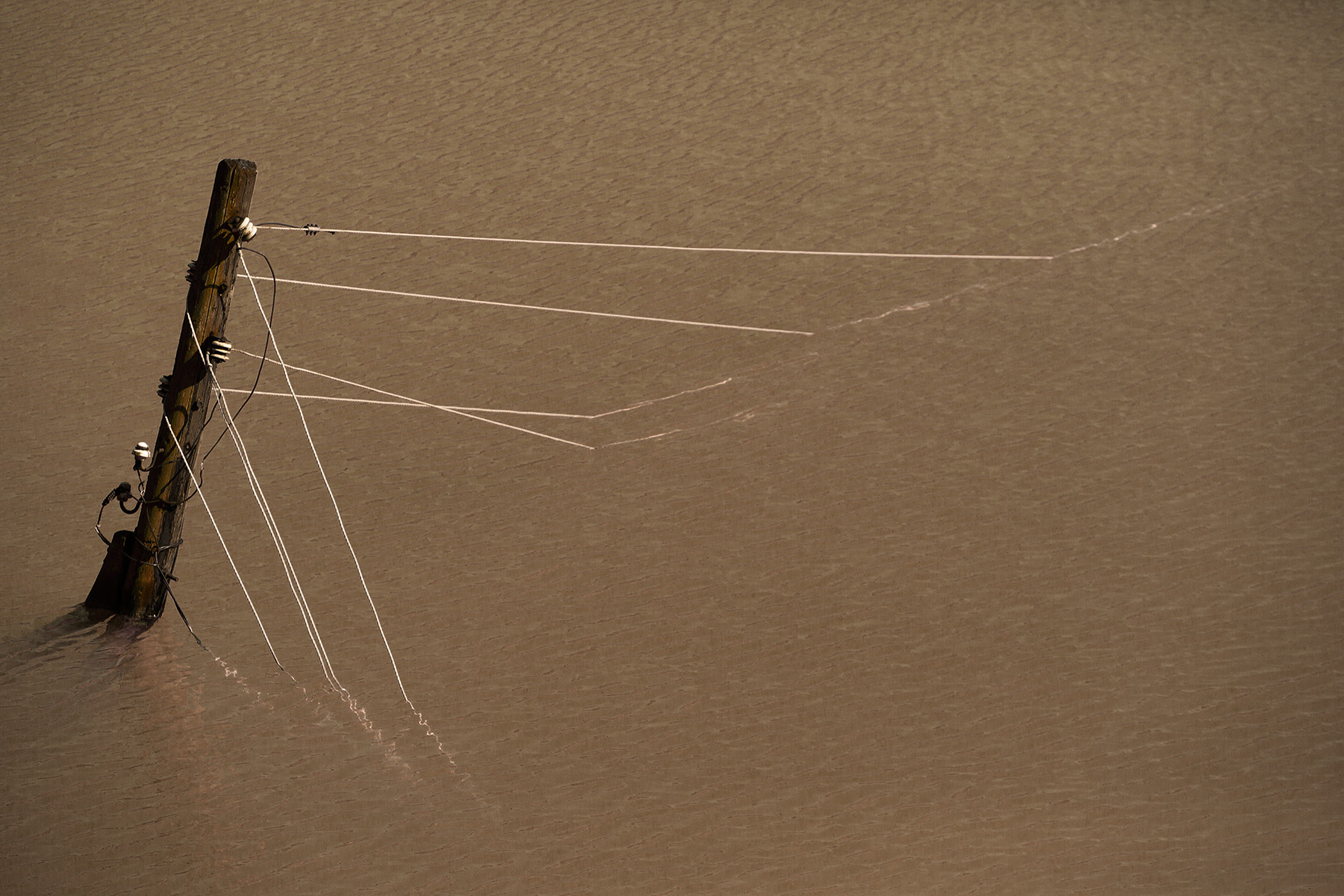
The Rio Salado, a tributary of the Rio Grande in New Mexico, is a desert ephemeral stream, or wash, that can at times run dry and at other times experience flash flooding from heavy rains in the summertime. Sudden and destructive, the floods can wash out existing infrastructure such as bridges, irrigation systems, and transmission lines.
An existing high-voltage transmission line in southern New Mexico crosses the Rio Salado near the town of San Acacia. Within the flood plain, a portion of this transmission line has a history of seasonal washouts, which destroy embedded wood pole structures and cause power outages.
A reconstruction of this portion of the line has been completed.
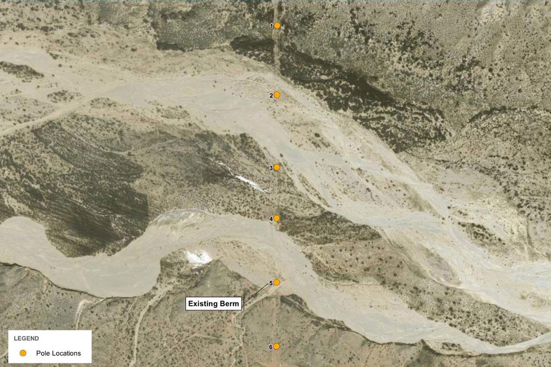
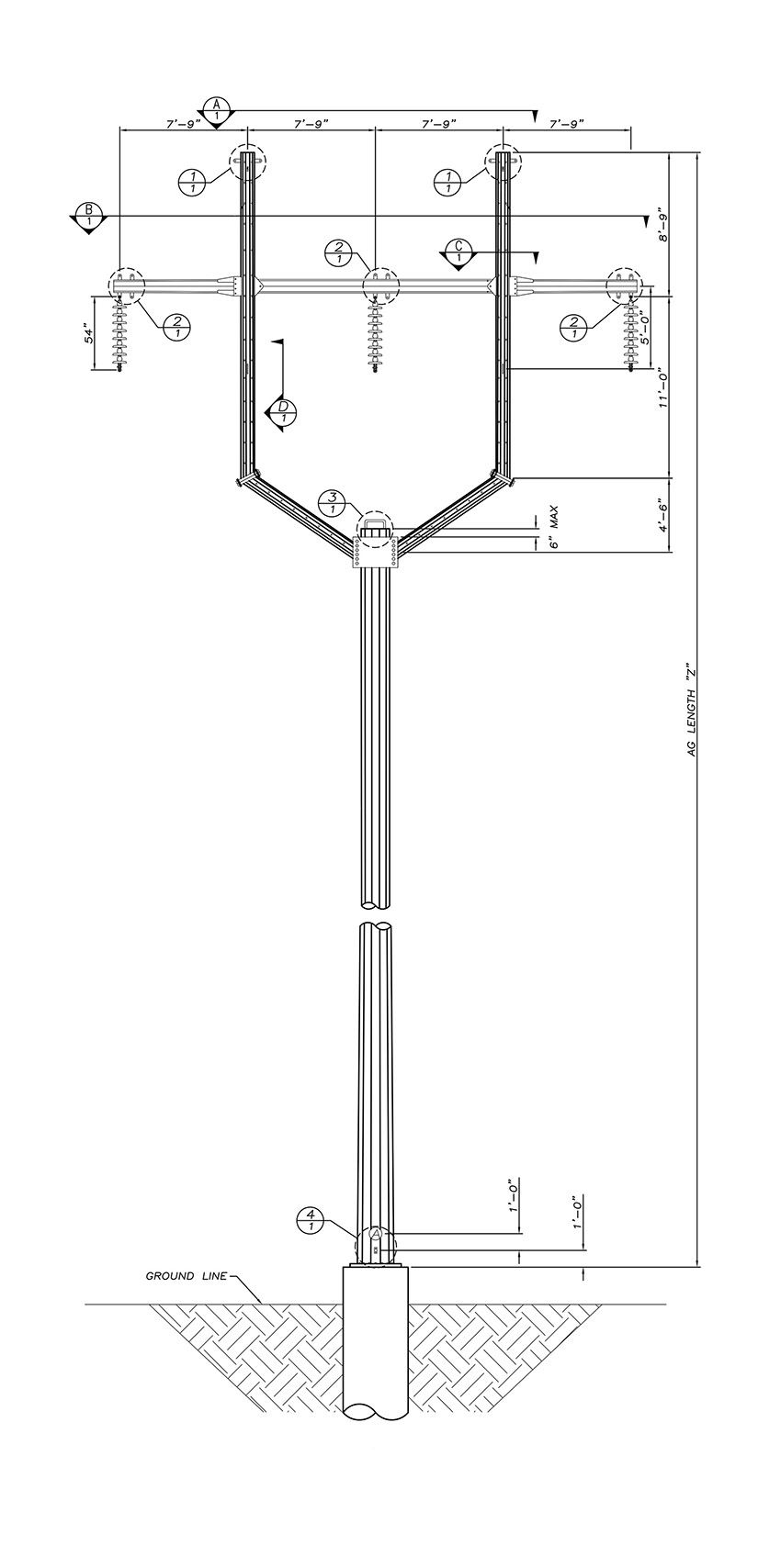
It includes four structurally robust steel monopole Y-frames founded on reinforced-concrete drilled piers that are designed to withstand hydraulic forces and ground loss from an extreme flood event.
For the Rio Salado, a soil boring was taken to a depth of approximately 60 ft at each of the six foundation locations. The upper soil layers indicated medium-dense, poorly graded sand with silt interlayered with well-graded sand.
The geotechnical investigation indicated soils near the transmission infrastructure have the potential to erode, since they are classified as a granular material compared to less erodible cohesive soils (clays) or rock.
Investigators also studied the Rio Salado’s lateral stream migration by reviewing historical aerial imagery over a 10-year period. They observed widening of the northern and southern reaches from 1996 to 2016. The northern reach increased between 1996 and 2009 and then remained relatively unchanged, indicating that the northern boundary had likely stabilized naturally.
The extent of the southern reach experienced a greater amount of change over the observation period. Prior to 2009, the wash extents were approximately 50 ft wide; however, by 2009, the wash extents widened to 250 ft, and by 2016, to 750 ft.
The change suggests that more strong water flows are being naturally directed into the southern reach, which could adversely impact the area’s transmission structures.
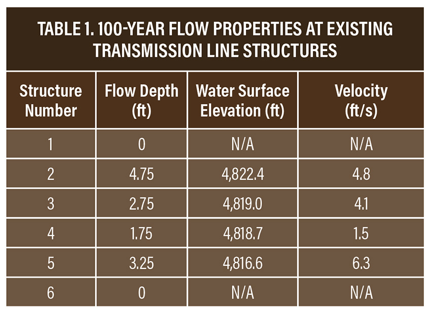
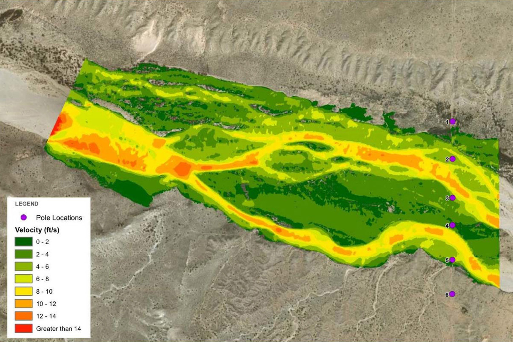
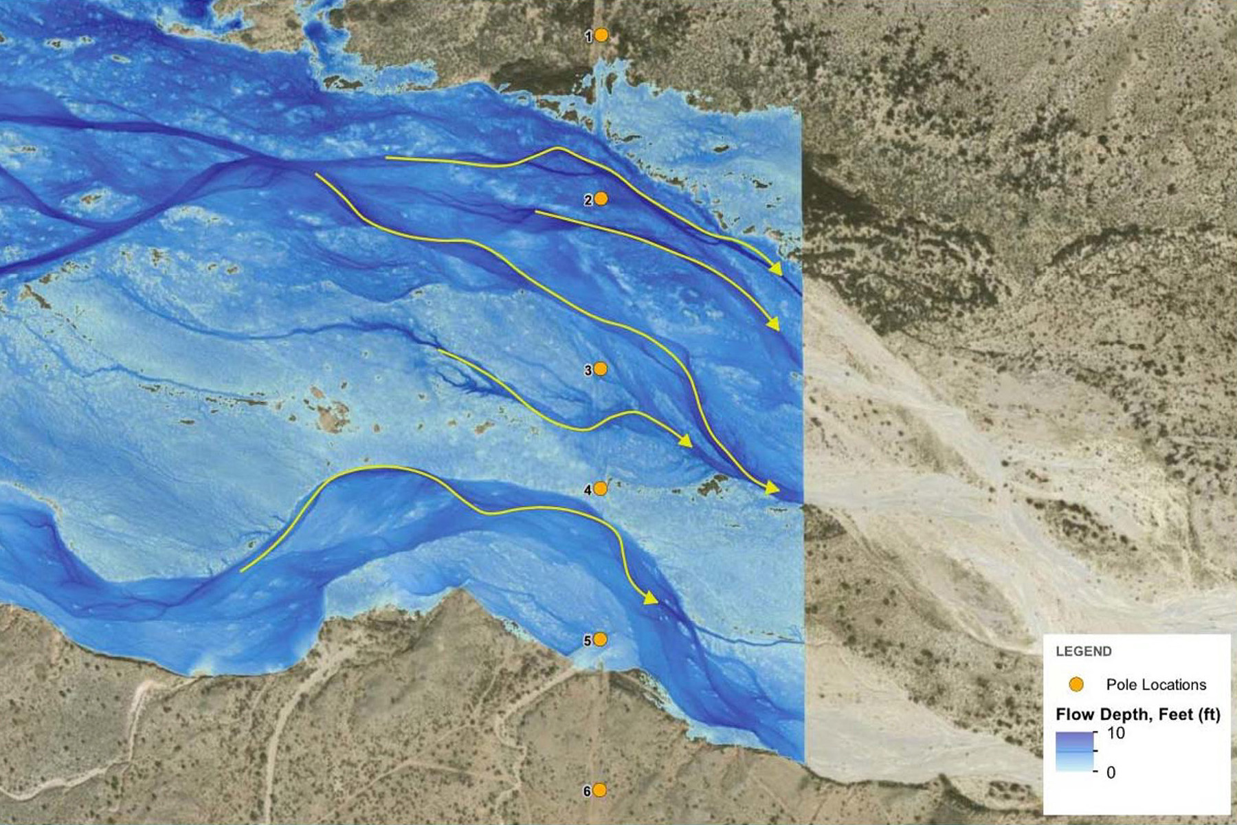
Three data sources were reviewed to determine the most appropriate flow event properties to use in the hydraulic analysis: United States Geological Survey Gage 08354000, USGS regression equations, and the New Mexico Department of Transportation drainage report for Rio Salado bridges 5959 and 5960 on Interstate 25. Table 1 shows the resulting 100-year flow depths, water surface elevations in feet, and velocities in feet per second based on a flow rate of 43,342 cfs reported from NMDOT at the existing transmission line structures.
Based on the results of the 2D hydraulics model, structures 1 and 6 are outside the bounds of the 100-year flow event. Structure 2 experiences the highest flow depth, while structure 5 sees the highest velocity. The maximum flow depth and velocity of the wash area not associated with a specific structure location was reported as a maximum depth of 6.8 ft and 12.1 ft/s.
The results of the hydraulic analysis can be used to assess ground loss potential in two ways:
- Use the properties identified in Table 1 on a site-specific structure basis.
- Use the maximum channel conditions not associated with specific structure locations.
The design team chose the latter approach because there were only four foundations with the same structure loading that used a common foundation design.
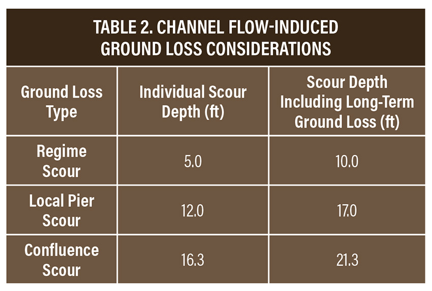
Three potential types of scour were identified and evaluated for a 100-year event for the structure foundation design: regime, local pier, and confluence. Regime scour (general scour or erosion of the streambed) was computed to identify the maximum scour associated with the 100-year event. Local pier scour typically forms as a transient scour hole around the foundation during the design event and tends to slowly fill in as water flow decreases.
Confluence scour was computed to represent the scour observed at the confluence of two stream braids. The calculation of confluence scour included the contribution from local pier scour, which occurs because of the foundation and obstructs the main channel. In addition, long-term ground loss was calculated as 5 ft for the overall channel to be added to the calculations for each of the previous scour mechanisms. The study recommended that each type of scour be considered individually with long-term ground loss values. The estimated flow-induced ground loss based on each individual condition is summarized in Table 2.
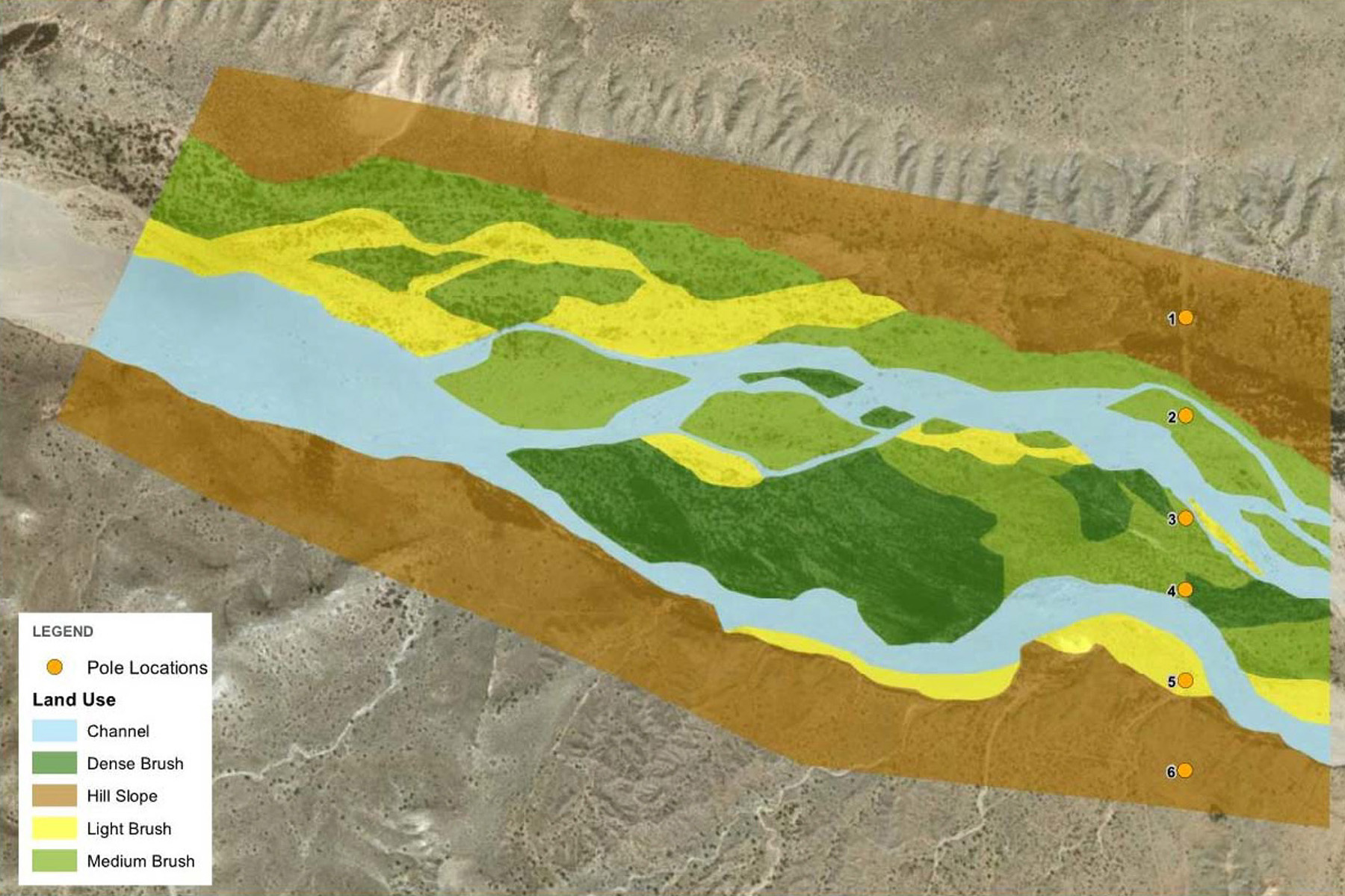
Floating debris can adversely affect a foundation’s structural resistance, resulting in a wider cross-section that will exhibit more pronounced scour. Additionally, increased pressure from hydraulic drag forces and debris impact to the foundation can destabilize and/or damage the foundation or structure. Observations of local debris from a field visit indicated that the site contained varying densities of desert vegetation, including shrubs and brush. Light brush and low-density vegetation were primarily observed within the washout area. Dense brush and high-density vegetation were observed on the overbanks of the wash. Vegetation buildup was observed around some of the existing wood pole structures.
Ultimate design
Based on the results of the geotechnical and hydraulic studies, the design for the reinforced-concrete drilled pier foundations to support the new Y-frame steel monopole structures incorporated several design elements:
- The top of the concrete elevation, accounted for as an increased amount of the foundation that sticks out of the ground, was specified to be one foot above the water surface elevation for the 100-year flow event.
- The hydraulic force on the pier was calculated as 5.9 kips for a 5.5 ft diameter pier, assuming a 6.8 ft maximum depth and 12.1 ft/s velocity. The hydraulic force was derived from equation 2.1 in the Federal Highway Administration Hydraulic Engineering Circular, No. 18, Evaluating Scour at Bridges, Fifth Edition, and was converted to an equivalent single-point shear force at the top of the foundation. This force was used as input into standard lateral-load foundation models.
- Confluence scour produced the maximum ground-loss depth and resulted in a total scour depth of 21.3 ft after the effects of long-term ground loss were included. The scour depth was not represented as a load but incorporated into the design as an increase in the foundation’s out-of-ground reveal.
- The force from debris buildup was calculated as 8.8 kips, derived from a 9.5 ft equivalent pier diameter. This accounts for additional drag forces due to the increase in the profile. The force calculated for debris was derived and applied in a manner similar to the hydraulic forces mentioned previously.
Aside from load development, current electrical industry codes and standards also lack guidance for appropriate probabilistic load combinations addressing simultaneous extreme events for the economic design of transmission foundations. For example, the chance of two extreme load events (such as a 100-year wind and a 100-year flood) occurring simultaneously is rare and highly unlikely within the target service life of a transmission line. Except in some coastal hurricane regions, scour resulting from a 100-year water flow event will follow the preceding heavy wind event. This poses two questions:
- What would be a statistically compatible wind event coincident with the design flood event?
- Conversely, what would be the appropriate channel flow rate during a design wind event?
Ultimately, an extreme event analysis was needed to answer these questions.
Extreme event analysis
Design of Highway Bridges for Extreme Events, a 2003 National Cooperative Highway Research Program extreme event report for highway bridge design, offers some insight into combined load probability assessment for simultaneous environmental events. Research on scour depth design using standard practices (HEC-18) indicates various levels of reliability when compared to observed results for bridge foundations.
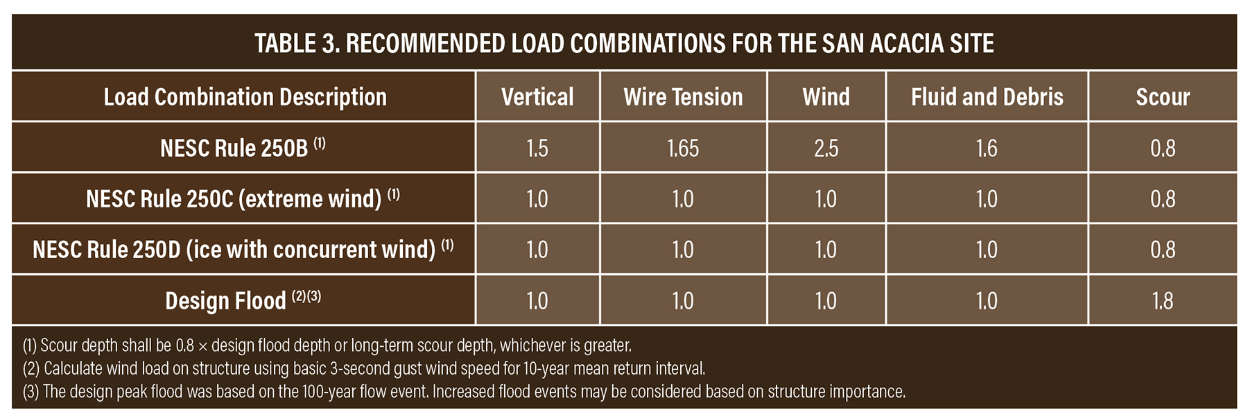
Using a target reliability index of 3.0, typical for the transmission industry, the compatible factor for design scour is 1.8. This scour load factor should be used with nominal wind and tension as the extreme scour case. Similarly, in combination with extreme wind events, the implied scour load factor becomes just under 0.8.
Other factors in determining load combinations include long-term ground loss versus transient scour conditions related to specific flow events. Channel degradation occurs over long periods of time and may happen over many flow events while embankments erode, the main flow channel wanders, and the stream channel degrades. These conditions impact channel geometry. The design maximum wind event could happen after these conditions are present and needs to be considered concurrent with the design wind event.
Table 3 summarizes the recommended load combinations for the drilled pier design for the San Acacia site. Load combinations required by the National Electric Safety Code (NESC) are included for the development of above-grade loads resulting from wind and ice events and conductor tension.
There are very few uniform standards, and very little industry guidance, for the foundation design of overhead power lines. Uniform guidance will aid in more efficient, consistent, and reliable foundation design.
Brittany Huntsberger, P.E., M.ASCE, is an engineering manager/structural leader at HDR Inc. in Billings, Montana.
This article first appeared in the September/October 2025 issue of Civil Engineering as “Anticipating the Worst.”
This article is based on the paper “Guidance on Load Combinations for Transmission Foundations,” which the author presented at the ASCE Electrical Transmission & Substation Structures Conference September 14-18 in Dallas. The paper will be published in the conference proceedings.
ASCE/SEI will publish the Manual of Practice for the Design of Overhead Line and Substation Foundations in early 2026. Three more MOPs are under development including: Inspection and Maintenance of Overhead Power Line Structures and Foundations, Failure Investigation of Overhead Power Line Structures and Foundations, and Structural Design of Overhead Power Lines Inspection.
ASCE/SEI are also working on new consensus standards to support the industry: one for prestressed concrete transmission pole structures and another for minimum design loads for structures supporting overhead power lines and wired telecommunications infrastructure.